-

Chapter 4: Objectives
- Upon completion of this chapter, you will be able to:
- Identify device connectivity options.
- Describe the purpose and functions of the physical layer in the network.
- Describe basic principles of the physical layer standards.
- Identify the basic characteristics of copper cabling.
- Build a UTP cable used in Ethernet networks.
- Describe fiber-optic cabling and its main advantages over other media.
- Describe wireless media.
- Select the appropriate media for a given requirement and connect devices.
- Describe the purpose and function of the data link layer in preparing communication for transmission on specific media.
- Describe the Layer 2 frame structure and identify generic fields.
- Identify several sources for the protocols and standards used by the data link layer.
- Compare the functions of logical topologies and physical topologies.
- Describe the basic characteristics of media control methods on WAN topologies.
- Describe the basic characteristics of media control methods on LAN topologies.
- Describe the characteristics and functions of the data link frame.
Chapter 4
- Physical Layer Protocols
- Network Media
- Data Link Layer Protocols
- Media Access Control
- Summary
-

Network Interface Cards

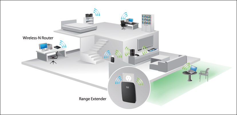
- Network Interface Cards (NICs) connect a device to the network. Ethernet NICs are used for a wired connection, as shown in Figure 1, whereas WLAN (Wireless Local Area Network) NICs are used for wireless. An end-user device may include one or both types of NICs. A network printer, for example, may only have an Ethernet NIC, and therefore, must connect to the network using an Ethernet cable. Other devices, such as tablets and smartphones, might only contain a WLAN NIC and must use a wireless connection. Not all physical connections are equal, in terms of the performance level, when connecting to a network. For example, a wireless device will experience degradation in performance based on its distance from a wireless access point. The further the device is from the access point, the weaker the wireless signal it receives. This can mean less bandwidth or no wireless connection at all. Figure 2 shows that a wireless range extender can be used to regenerate the wireless signal to other parts of the house that are too far from the wireless access point. Alternatively, a wired connection will not degrade in performance. All wireless devices must share access to the airwaves connecting to the wireless access point. This means slower network performance may occur as more wireless devices access the network simultaneously. A wired device does not need to share its access to the network with other devices. Each wired device has a separate communications channel over its Ethernet cable. This is important when considering some applications, such as online gaming, streaming video, and video conferencing, which require more dedicated bandwidth than other applications. Over the next couple of topics, you will learn more about the physical layer connections that occur and how those connections affect the transportation of data.
Types of Connections
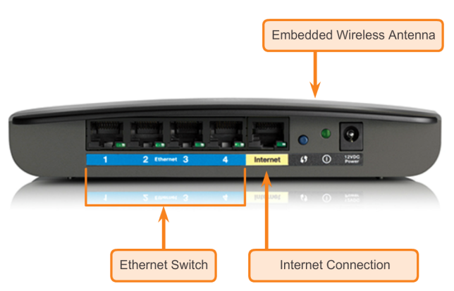
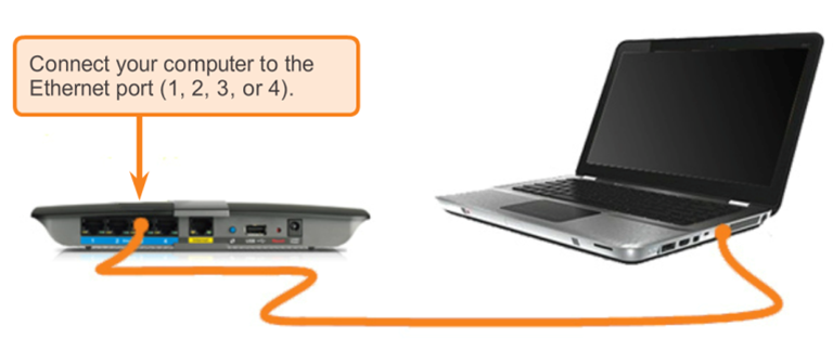
- Whether connecting to a local printer in the home or a web site in another country, before any network communications can occur, a physical connection to a local network must be established. A physical connection can be a wired connection using a cable or a wireless connection using radio waves. The type of physical connection used is dependent upon the setup of the network. For example, in many corporate offices employees have desktop or laptop computers that are physically connected, via cable, to a shared switch. This type of setup is a wired network. Data is transmitted through a physical cable. In addition to wired connections, some businesses may also offer wireless connections for laptops, tablets, and smartphones. With wireless devices, data is transmitted using radio waves. The use of wireless connectivity is becoming more common as individuals, and businesses alike, discover the advantages of offering this type of service. To offer wireless capability, devices on a wireless network must be connected to a wireless access point (AP). Switch devices and wireless access points are often two separate dedicated devices within a network implementation. However, there are also devices that offer both wired and wireless connectivity. In many homes, for example, individuals are implementing home integrated service routers (ISRs), as shown in Figure 1. ISRs offer a switching component with multiple ports, allowing multiple devices to be connected to the local area network (LAN) using cables, as shown in Figure 2. Additionally, many ISRs also include an AP, which allows wireless devices to connect as well.
-
Physical Layer Standards cont...
- There are many different international and national organizations, regulatory government organizations, and private companies involved in establishing and maintaining physical layer standards. For instance, the physical layer hardware, media, encoding, and signaling standards are defined and governed by the:
- International Organization for Standardisation (ISO)
- Telecommunications Industry Association/Electronic Industries Association (TIA/EIA)
- International Telecommunication Union (ITU)
- American National Standards Institute (ANSI)
- Institute of Electrical and Electronics Engineers (IEEE)
- National telecommunications regulatory authorities including the Federal Communication Commission (FCC) in the USA and the European Telecommunications Standards Institute (ETSI)
- In addition to these, there are often regional cabling standards groups such as CSA (Canadian Standards Association), CENELEC (European Committee for Electrotechnical Standardisation), and JSA/JIS (Japanese Standards Association), developing local specifications.
Bandwidth
- Different physical media support the transfer of bits at different rates. Data transfer is usually discussed in terms of bandwidth and throughput. Bandwidth is the capacity of a medium to carry data. Digital bandwidth measures the amount of data that can flow from one place to another in a given amount of time. Bandwidth is typically measured in kilobits per second (kb/s), megabits per second (Mb/s), or gigabits per second (Gb/s). Bandwidth is sometimes thought of as the speed that bits travel, however this is not accurate. For example, in both 10Mb/s and 100Mb/s Ethernet, the bits are sent at the speed of electricity. The difference is the number of bits that are transmitted per second.
- A combination of factors determines the practical bandwidth of a network:
- he properties of the physical media
- The technologies chosen for signaling and detecting network signals
- Physical media properties, current technologies, and the laws of physics all play a role in determining the available bandwidth. The 💡 table shows the commonly used units of measure for bandwidth.
The Physical Layer
- The OSI physical layer provides the means to transport the bits that make up a data link layer frame across the network media. This layer accepts a complete frame from the data link layer and encodes it as a series of signals that are transmitted onto the local media. The encoded bits that comprise a frame are received by either an end device or an intermediate device.
- The process that data undergoes from a source node to a destination node is:
- The user data is segmented by the transport layer, placed into packets by the network layer, and further encapsulated into frames by the data link layer.
- The physical layer encodes the frames and creates the electrical, optical, or radio wave signals that represent the bits in each frame.
- These signals are then sent on the media, one at a time.
- The destination node physical layer retrieves these individual signals from the media, restores them to their bit representations, and passes the bits up to the data link layer as a complete frame.
Physical Layer Media
- There are three basic forms of network media. The physical layer produces the representation and groupings of bits for each type of media as:
- Copper cable: The signals are patterns of electrical pulses.
- Fiber-optic cable: The signals are patterns of light.
- Wireless: The signals are patterns of microwave transmissions.
- The 📷 figure displays signaling examples for copper, fiber-optic, and wireless.
- To enable physical layer interoperability, all aspects of these functions are governed by standards organisations.
Physical Layer Standards
- The protocols and operations of the upper OSI layers are performed in software designed by software engineers and computer scientists. The services and protocols in the TCP/IP suite are defined by the Internet Engineering Task Force (IETF). The physical layer consists of electronic circuitry, media, and connectors developed by engineers. Therefore, it is appropriate that the standards governing this hardware are defined by the relevant electrical and communications engineering organisations.
X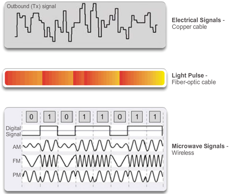 X
XUnit of Bandwidth Abbreviation Equivalence Bits per second b/s 1 b/s = fundamental unit of bandwidth Kilobits per second kb/s 1 kb/s = 1,000 bps = 10^3 bps Megabits per second Mb/s 1 Mb/s = 1,000,000 bps = 10^6 bps Gigabits per second Gb/s 1 Gb/s = 1,000,000,000 bps = 10^9 bps Terabits per second Tb/s 1 Tb/s = 1,000,000,000,000 bps = 10^12 bps -
Throughput
- Throughput is the measure of the transfer of bits across the media over a given period of time.
- Due to a number of factors, throughput usually does not match the specified bandwidth in physical layer implementations. Many factors influence throughput, including:
- The amount of traffic
- The type of traffic
- The latency created by the number of network devices encountered between source and destination
- Latency refers to the amount of time, to include delays, for data to travel from one given point to another.
- In an internetwork or network with multiple segments, throughput cannot be faster than the slowest link in the path from source to destination. Even if all or most of the segments have high bandwidth, it will only take one segment in the path with low throughput to create a bottleneck to the throughput of the entire network. There are many online speed tests that can reveal the throughput of an Internet connection. The 📷 figure provides sample results from a speed test. There is a third measurement to assess the transfer of usable data that is known as goodput. Goodput is the measure of usable data transferred over a given period of time. Goodput is throughput minus traffic overhead for establishing sessions, acknowledgments, and encapsulation.
Types of Physical Media
- The physical layer produces the representation and groupings of bits as voltages, radio frequencies, or light pulses. Various standards organizations have contributed to the definition of the physical, electrical, and mechanical properties of the media available for different data communications. These specifications guarantee that cables and connectors will function as anticipated with different data link layer implementations. As an example, standards for copper media are defined for the:
- Type of copper cabling used
- Bandwidth of the communication
- Type of connectors used
- Pinout and color codes of connections to the media
- Maximum distance of the media
- The 📷 figure shows different types of interfaces and ports available on a 1941 router.
X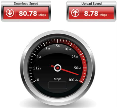 X
X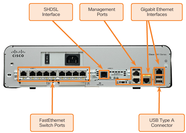
-

Copper Media

- There are three main types of copper media used in networking:
- 💡 Unshielded Twisted-Pair (UTP)
- 💡 Shielded Twisted-Pair (STP)
- 💡 Coaxial
- These cables are used to interconnect nodes on a LAN and infrastructure devices such as switches, routers, and wireless access points. Each type of connection and the accompanying devices has cabling requirements stipulated by physical layer standards. Different physical layer standards specify the use of different connectors. These standards specify the mechanical dimensions of the connectors and the acceptable electrical properties of each type. Networking media use modular jacks and plugs to provide easy connection and disconnection. Also, a single type of physical connector may be used for multiple types of connections. For example, the RJ-45 connector is widely used in LANs with one type of media and in some WANs with another media type.
Characteristics of Copper Cabling
- Networks use copper media because it is inexpensive, easy to install and has low resistance to electrical current. However, copper media is limited by distance and signal interference. Data is transmitted on copper cables as electrical pulses. A detector in the network interface of a destination device must receive a signal that can be successfully decoded to match the signal sent. However, the longer the signal travels, the more it deteriorates. This is referred to as signal attenuation. For this reason, all copper media must follow strict distance limitations as specified by the guiding standards. The timing and voltage values of the electrical pulses are also susceptible to interference from two sources:
- Electromagnetic interference (EMI) or radio frequency interference (RFI) - EMI and RFI signals can distort and corrupt the data signals being carried by copper media. Potential sources of EMI and RFI include radio waves and electromagnetic devices, such as fluorescent lights or electric motors as shown in the 📷 figure.
- Crosstalk - Crosstalk is a disturbance caused by the electric or magnetic fields of a signal on one wire to the signal in an adjacent wire. In telephone circuits, crosstalk can result in hearing part of another voice conversation from an adjacent circuit. Specifically, when an electrical current flows through a wire, it creates a small, circular magnetic field around the wire, which can be picked up by an adjacent wire.
- To counter the negative effects of EMI and RFI, some types of copper cables are wrapped in metallic shielding and require proper grounding connections. To counter the negative effects of crosstalk, some types of copper cables have opposing circuit wire pairs twisted together, which effectively cancels the crosstalk. The susceptibility of copper cables to electronic noise can also be limited by:
- Selecting the cable type or category most suited to a given networking environment.
- Designing a cable infrastructure to avoid known and potential sources of interference in the building structure.
- Using cabling techniques that include the proper handling and termination of the cables.
X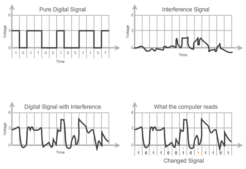 X
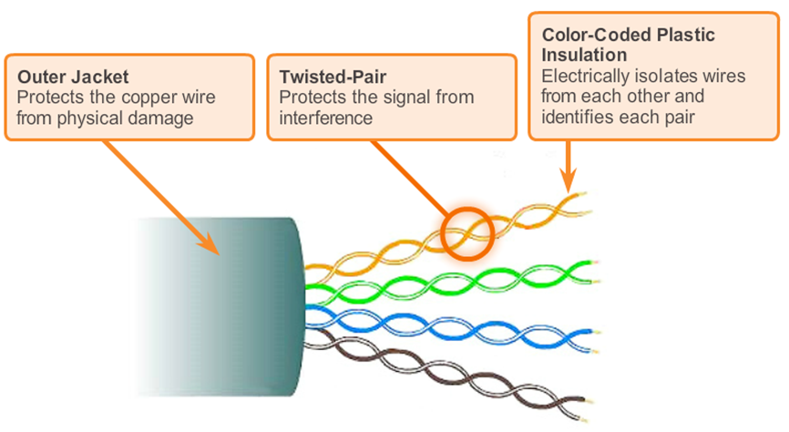
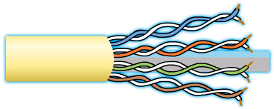
X- Unshielded twisted-pair (UTP) cabling is the most common networking media. UTP cabling, terminated with RJ-45 connectors, is used for interconnecting network hosts with intermediate networking devices, such as switches and routers.
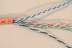
- In LANs, UTP cable consists of four pairs of color-coded wires that have been twisted together and then encased in a flexible plastic sheath that protects from minor physical damage. The twisting of wires helps protect against signal interference from other wires.
- As seen in the figure, the color codes identify the individual pairs and wires and aid in cable termination.
 X
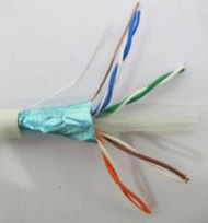
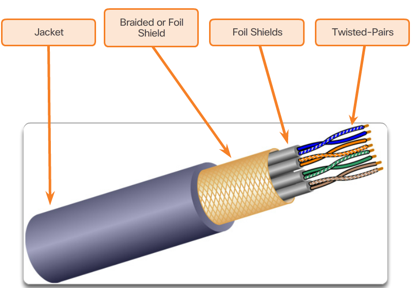
X- Shielded twisted-pair (STP) provides better noise protection than UTP cabling. However, compared to UTP cable, STP cable is significantly more expensive and difficult to install. Like UTP cable, STP uses an RJ-45 connector.
- STP cables combine the techniques of shielding to counter EMI and RFI, and wire twisting to counter crosstalk. To gain the full benefit of the shielding, STP cables are terminated with special shielded STP data connectors. If the cable is improperly grounded, the shield may act as an antenna and pick up unwanted signals.
- The STP cable shown uses four pairs of wires, each wrapped in a foil shield, which are then wrapped in an overall metallic braid or foil.
 X
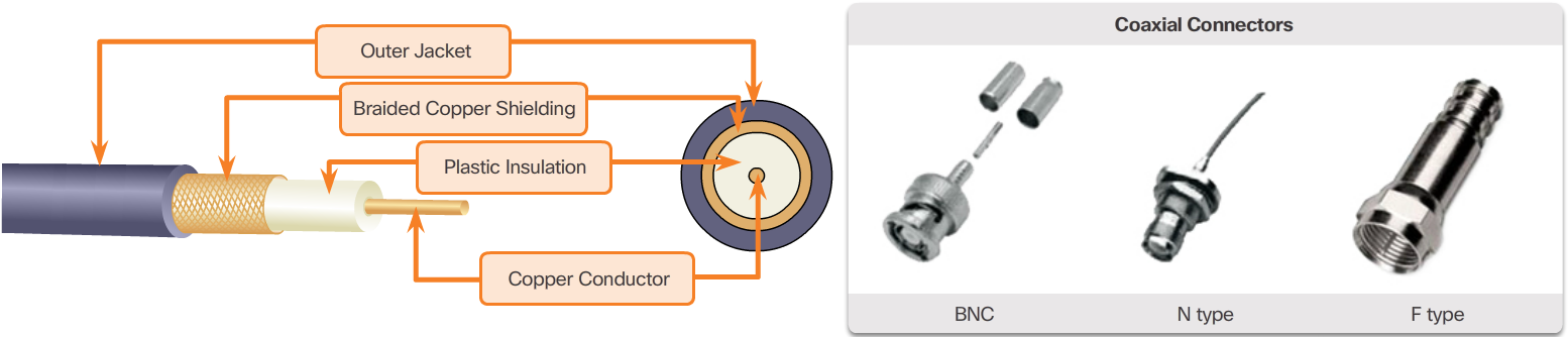
X- Coaxial cable, or coax for short, gets its name from the fact that there are two conductors that share the same axis. As shown in the figure, coaxial cable consists of:
- A copper conductor used to transmit the electronic signals.
- A layer of flexible plastic insulation surrounding a copper conductor.
- The insulating material is surrounded in a woven copper braid, or metallic foil, that acts as the second wire in the circuit and as a shield for the inner conductor. This second layer, or shield, also reduces the amount of outside electromagnetic interference.
- The entire cable is covered with a cable jacket to prevent minor physical damage.
- There are different types of connectors used with coax cable. Although UTP cable has essentially replaced coaxial cable in modern Ethernet installations, the coaxial cable design is used in:
- Wireless installations: Coaxial cables attach antennas to wireless devices. The coaxial cable carries radio frequency (RF) energy between the antennas and the radio equipment.
- Cable Internet installations: Cable service providers provide Internet connectivity to their customers by replacing portions of the coaxial cable and supporting amplification elements with fiber-optic cable. However, the wiring inside the customer's premises is still coax cable.
-
Properties of UTP Cabling
- When used as a networking medium, unshielded twisted-pair (UTP) cabling consists of four pairs of color-coded copper wires that have been twisted together and then encased in a flexible plastic sheath. Its small size can be advantageous during installation. UTP cable does not use shielding to counter the effects of EMI and RFI. Instead, cable designers have discovered that they can limit the negative effect of crosstalk by:
- Cancellation: Designers now pair wires in a circuit. When two wires in an electrical circuit are placed close together, their magnetic fields are the exact opposite of each other. Therefore, the two magnetic fields cancel each other and also cancel out any outside EMI and RFI signals.
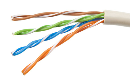
- Varying the number of twists per wire pair: To further enhance the cancellation effect of paired circuit wires, designers vary the number of twists of each wire pair in a cable. UTP cable must follow precise specifications governing how many twists or braids are permitted per meter (3.28 feet) of cable. Notice in the figure that the orange/orange white pair is twisted less than the blue/blue white pair. Each colored pair is twisted a different number of times.
- UTP cable relies solely on the cancellation effect produced by the twisted wire pairs to limit signal degradation and effectively provide self-shielding for wire pairs within the network media.
Copper Media Safety
- All three types of copper media are susceptible to fire and electrical hazards. Fire hazards exist because cable insulation and sheaths may be flammable, or produce toxic fumes when heated or burned. Building authorities or organizations may stipulate related safety standards for cabling and hardware installations. Electrical hazards are a potential problem because copper wires can conduct electricity in undesirable ways. This could subject personnel and equipment to a range of electrical hazards. For example, a defective network device could conduct currents to the chassis of other network devices. Additionally, network cabling could present undesirable voltage levels when used to connect devices that have power sources with different ground potentials. Such situations are possible when copper cabling is used to connect networks in different buildings or on separate floors that use disparate power facilities. Finally, copper cabling may conduct voltages caused by lightning strikes to network devices. The result of undesirable voltages and currents can include damage to network devices and connected computers, or injury to personnel. It is important that copper cabling be installed appropriately, and according to the relevant specifications and building codes, in order to avoid potentially dangerous and damaging situations. The 📷 figure displays proper cabling practices that help to prevent potential fire and electrical hazards.
X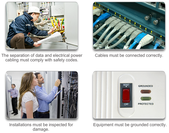
-
UTP Connectors
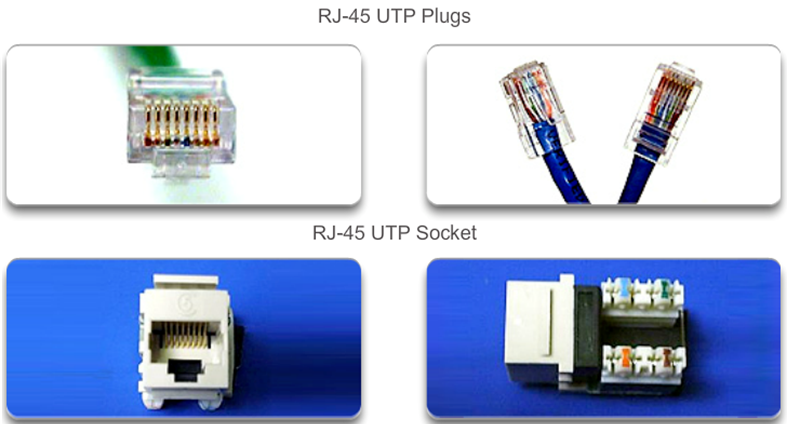
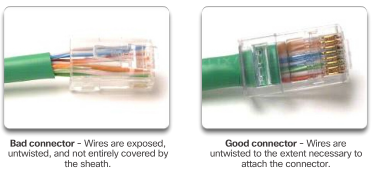
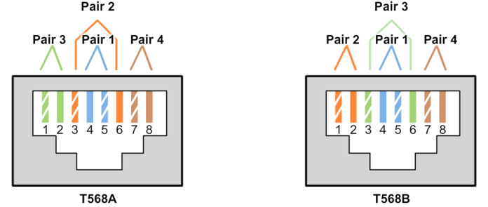
- UTP cable is usually terminated with an RJ-45 connector. This connector is used for a range of physical layer specifications, one of which is Ethernet. The TIA/EIA-568 standard describes the wire color codes to pin assignments (pinouts) for Ethernet cables. As shown in Figure1, the RJ-45 connector is the male component, crimped at the end of the cable. The socket is the female component of a network device, wall, cubicle partition outlet, or patch panel. Each time copper cabling is terminated; there is the possibility of signal loss and the introduction of noise into the communication circuit. When terminated improperly, each cable is a potential source of physical layer performance degradation. It is essential that all copper media terminations be of high quality to ensure optimum performance with current and future network technologies. Figure 2 displays an example of a badly terminated UTP cable and a well terminated UTP cable.
UTP Cabling Standards

- Used for voice communication
- Most often used for phone lines

- Used for data transmission
- Cat5 supports 100 Mb/s and can support 1000 Mb/s, but it is not recommended
- Cat5e supports 1000 Mb/s
- Used for data transmission
- An added separator is between each pair of wires allowing it to function at higher speeds
- Supports 1000 Mb/s - 10 Gb/s, though 10 Gb/s is not recommended
- UTP cabling conforms to the standards established jointly by the TIA/EIA. Specifically, TIA/EIA-568 stipulates the commercial cabling standards for LAN installations and is the standard most commonly used in LAN cabling environments. Some of the elements defined are:
- Cable types
- Cable lengths
- Connectors
- Cable termination
- Methods of testing cable
- The electrical characteristics of copper cabling are defined by the Institute of Electrical and Electronics Engineers (IEEE). IEEE rates UTP cabling according to its performance. Cables are placed into categories based on their ability to carry higher bandwidth rates. For example, Category 5 (Cat5) cable is used commonly in 100BASE-TX Fast Ethernet installations. Other categories include Enhanced Category 5 (Cat5e) cable, Category 6 (Cat6), and Category 6a. Cables in higher categories are designed and constructed to support higher data rates. As new gigabit speed Ethernet technologies are being developed and adopted, Cat5e is now the minimally acceptable cable type, with Cat6 being the recommended type for new building installations. Click each category of cable to learn more about their properties. Some manufacturers are making cables exceeding the TIA/EIA Category 6a specifications and refer to these as Category 7.
-
Testing UTP Cables
- After installation, a UTP cable tester, like the one shown in the 📷 figure, should be used to test for the following parameters:
- Wire map
- Cable length
- Signal loss due to attenuation
- Crosstalk
- It is recommended to check thoroughly that all UTP installation requirements have been met.
Properties of Fiber-Optic Cabling
- Optical fiber cable transmits data over longer distances and at higher bandwidths than any other networking media. Unlike copper wires, fiber-optic cable can transmit signals with less attenuation and is completely immune to EMI and RFI. Optical fiber is commonly used to interconnect network devices. Optical fiber is a flexible, but extremely thin, transparent strand of very pure glass, not much bigger than a human hair. Bits are encoded on the fiber as light impulses. The fiber-optic cable acts as a waveguide, or “light pipe,” to transmit light between the two ends with minimal loss of signal. As an analogy, consider an empty paper towel roll with the inside coated like a mirror. It is a thousand meters in length, and a small laser pointer is used to send Morse code signals at the speed of light. Essentially that is how a fiber-optic cable operates, except that it is smaller in diameter and uses sophisticated light technologies. Fiber-optic cabling is now being used in four types of industry:
- Enterprise Networks: Used for backbone cabling applications and interconnecting infrastructure devices.
- Fiber-to-the-Home (FTTH): Used to provide always-on broadband services to homes and small businesses.
- Long-Haul Networks: Used by service providers to connect countries and cities.
- Submarine Networks: Used to provide reliable high-speed, high-capacity solutions capable of surviving in harsh undersea environments up to transoceanic distances. Click here to view a telegeography map that depicts the location of submarine cables.
- Our focus in this course is the use of fiber within the enterprise.
Types of UTP Cable
- Different situations may require UTP cables to be wired according to different wiring conventions. This means that the individual wires in the cable have to be connected in different orders to different sets of pins in the RJ-45 connectors.
- The following are the main cable types that are obtained by using specific wiring conventions:
- Ethernet Straight-through: The most common type of networking cable. It is commonly used to interconnect a host to a switch and a switch to a router.
- Ethernet Crossover: A cable used to interconnect similar devices. For example to connect a switch to a switch, a host to a host, or a router to a router.
- Rollover: A Cisco proprietary cable used to connect a workstation to a router or switch console port.
- The figure shows the UTP cable type, related standards, and typical application of these cables. It also identifies the individual wire pairs for the TIA-568A and TIA-568B standards.
- Using a crossover or straight-through cable incorrectly between devices may not damage the devices, but connectivity and communication between the devices will not take place. This is a common error in the lab and checking that the device connections are correct should be the first troubleshooting action if connectivity is not achieved.
Cable-Type Standard Application Ethernet Straight-through Both ends T568A or both ends T568B Connects a network host or a network device such as a switch or hub Ethernet Crossover One end T568A, other end T568B - Connects two network hosts
- Connects two network intermediary devices (switch to switch, or router to router)
Rollover Cisco proprietary Connects a workstation serial port to a router console port, using an adaptor X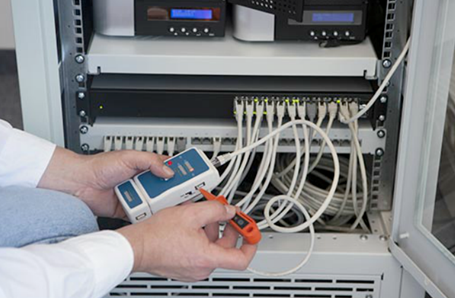
-
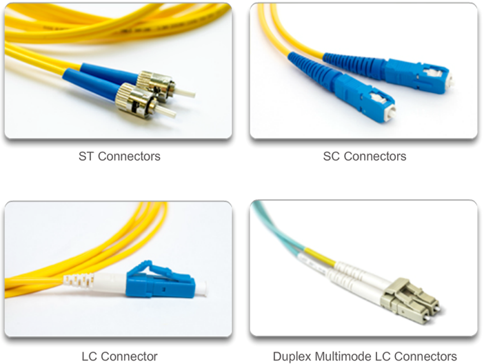
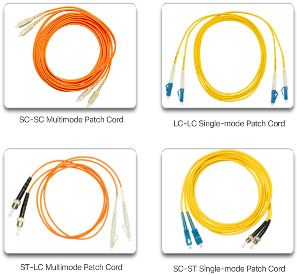
Fiber-Optic Connectors cont...
- Because light can only travel in one direction over optical fiber, two fibers are required to support the full duplex operation. Therefore, fiber-optic patch cables bundle together two optical fiber cables and terminate them with a pair of standard single fiber connectors. Some fiber connectors accept both the transmitting and receiving fibers in a single connector known as a duplex connector, as shown in the Duplex Multimode LC Connector in Figure 1. Fiber patch cords are required for interconnecting infrastructure devices. Figure 2 displays various common patch cords. The use of color distinguishes between single-mode and multimode patch cords. A yellow jacket is for single-mode fiber cables and orange (or aqua) for multimode fiber cables. Fiber cables should be protected with a small plastic cap when not in use.
Fiber Media Cable Design
- Optical fiber is composed of two kinds of glass (core and cladding) and a protective outer shield (jacket). Although the optical fiber is very thin and susceptible to sharp bends, the properties of the core and cladding make it very strong. Optical fiber is durable and is deployed in harsh environmental conditions in networks all around the world.
Types of Fiber Media
- Light pulses representing the transmitted data as bits on the media are generated by either:
- Lasers
- Light emitting diodes (LEDs)
- Electronic semiconductor devices called photodiodes detect the light pulses and convert them to voltages. The laser light transmitted over fiber-optic cabling can damage the human eye. Care must be taken to avoid looking into the end of an active optical fiber. Fiber-optic cables are broadly classified into two types:
- Single-mode fiber (SMF): Consists of a very small core and uses expensive laser technology to send a single ray of light. Popular in long-distance situations spanning hundreds of kilometers, such as those required in long haul telephony and cable TV applications.
- Multimode fiber (MMF): Consists of a larger core and uses LED emitters to send light pulses. Specifically, light from an LED enters the multimode fiber at different angles. Popular in LANs because they can be powered by low-cost LEDs. It provides bandwidth up to 10 Gb/s over link lengths of up to 550 meters.
- One of the highlighted differences between multimode and single-mode fiber is the amount of dispersion. Dispersion refers to the spreading out of a light pulse over time. The more dispersion there is, the greater the loss of signal strength.
Fiber-Optic Connectors
- An optical fiber connector terminates the end of an optical fiber. A variety of optical fiber connectors are available. The main differences among the types of connectors are dimensions and methods of coupling. Businesses decide on the types of connectors that will be used, based on their equipment.
-
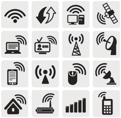
Properties of Wireless Media
- Wireless media carry electromagnetic signals that represent the binary digits of data communications using radio or microwave frequencies. Wireless media provides the greatest mobility options of all media, and the number of wireless-enabled devices continues to increase. As network bandwidth options increase, wireless is quickly gaining in popularity in enterprise networks. The figure highlights various wireless-related symbols. Wireless does have some areas of concern, including:
- Coverage area: Wireless data communication technologies work well in open environments. However, certain construction materials used in buildings and structures, and the local terrain, will limit the effective coverage.
- Interference: Wireless is susceptible to interference and can be disrupted by such common devices as household cordless phones, some types of fluorescent lights, microwave ovens, and other wireless communications.
- Security: Wireless communication coverage requires no access to a physical strand of media. Therefore, devices and users, not authorized for access to the network, can gain access to the transmission. Network security is a major component of wireless network administration.
- Shared medium: WLANs operate in half-duplex, which means only one device can send or receive at a time. The wireless medium is shared amongst all wireless users. The more users needing to access the WLAN simultaneously, results in less bandwidth for each user. Half-duplex is discussed later in this chapter.
- Although wireless is increasing in popularity for desktop connectivity, copper and fiber are the most popular physical layer media for network deployments.
Testing Fiber Cables
- Terminating and splicing fiber-optic cabling requires special training and equipment. Incorrect termination of fiber-optic media will result in diminished signaling distances or complete transmission failure. Three common types of fiber-optic termination and splicing errors are:
- Misalignment: The fiber-optic media are not precisely aligned to one another when joined.
- End gap: The media does not completely touch at the splice or connection.
- End finish: The media ends are not well polished, or dirt is present at the termination.
- A quick and easy field test can be performed by shining a bright flashlight into one end of the fiber while observing the other end. If light is visible, the fiber is capable of passing light. Although this does not ensure performance, it is a quick and inexpensive way to find a broken fiber. An Optical Time Domain Reflectometer (OTDR) can be used to test each fiber-optic cable segment. This device injects a test pulse of light into the cable and measures backscatter and reflection of light detected as a function of time. The OTDR will calculate the approximate distance at which these faults are detected along the length of the cable.
Fiber Versus Copper
- There are many advantages to using fiber-optic cable compared to copper cables. The table highlights some of these differences. Given that the fibers used in fiber-optic media are not electrical conductors, the media is immune to electromagnetic interference and will not conduct unwanted electrical currents due to grounding issues. Optical fibers are thin and have a relatively low signal loss and can be operated at much greater lengths than copper media. Some optical fiber physical layer specifications allow lengths that can reach multiple kilometers. At present, in most enterprise environments, optical fiber is primarily used as backbone cabling for high-traffic point-to-point connections between data distribution facilities and for the interconnection of buildings in multi-building campuses. Because optical fiber does not conduct electricity and has a low signal loss, it is well suited for these uses.
Implementation Issues UTP Cabling Fiber-optic Cabling Bandwidth supported 10 Mb/s - 10 Gb/s 10 Mb/s - 100 Gb/s Distance Relatively short
(1 - 100 meters)Relatively high
(1 - 100,000 meters)Immunity to EMI and RFI Low High
(Completely immune)Immunity to electrical hazards Low High
(Completely immune)Media and connector costs Lowest Highest Installation skills required Lowest Highest Safety precautions Lowest Highest -
Types of Wireless Media
- The IEEE and telecommunications industry standards for wireless data communications cover both the data link and physical layers. Click on each standard for more information. Note: Other wireless technologies such as cellular and satellite communications can also provide data network connectivity. However, these wireless technologies are out of scope for this chapter. In each of these standards, physical layer specifications are applied to areas that include:
- Data to radio signal encoding
- Frequency and power of transmission
- Signal reception and decoding requirements
- Antenna design and construction
- Wi-Fi is a trademark of the Wi-Fi Alliance. Wi-Fi is used with certified products that belong to WLAN devices that are based on the IEEE 802.11 standards.
- 💡 Wifi
- 💡 Bluetooth
- 💡 WiMAX
Wireless LAN
- A common wireless data implementation is enabling devices to connect wirelessly via a LAN. In general, a wireless LAN requires the following network devices:
- Wireless Access Point (AP): Concentrates the wireless signals from users and connects to the existing copper-based network infrastructure, such as Ethernet. Home and small business wireless routers integrate the functions of a router, switch, and access point into one device.
- Wireless NIC adapters: Provide wireless communication capability to each network host.
- As the technology has developed, a number of WLAN Ethernet-based standards have emerged. Care needs to be taken in purchasing wireless devices to ensure compatibility and interoperability. The benefits of wireless data communications technologies are evident, especially the savings on costly premises wiring and the convenience of host mobility. Network administrators need to develop and apply stringent security policies and processes to protect wireless LANs from unauthorized access and damage.
Standard Maximum
SpeedFrequency Backwards
Compatible802.11a 54 Mbps 5 GHz No 802.11b 11 Mbps 2.4 GHz No 802.11g 54 Mbps 2.4 GHz 802.11b 802.11n 600 Mbps 2.4 GHz or 5 GHz 802.11b/g 802.11ac 1.3 Gbps
(1300 Mbps)2.4 GHz and 5.5 GHz 802.11b/g/n 802.11ad 7 Gbps
(7000 Mbps)2.4 GHz, 5 GHz and 60 GHz 802.11b/g/n/ac XWi-Fi: Standard IEEE 802.11
- Wireless LAN (WLAN) technology, commonly referred to as Wi-Fi. WLAN uses a contention-based protocol known as Carrier Sense Multiple Access/Collision Avoidance (CSMA/CA). The wireless NIC must first listen before transmitting to determine if the radio channel is clear. If another wireless device is transmitting, then the NIC must wait until the channel is clear. CSMA/CA is discussed later in this chapter.
XStandard IEEE 802.15: Bluetooth
- Wireless Personal Area Network (WPAN) standard, commonly known as "Bluetooth", uses a device pairing process to communicate over distances from 1 to 100 meters.
XStandard IEEE 802.16: WiMAX
- Commonly known as Worldwide Interoperability for Microwave Access (WiMAX), uses a point-to-multipoint topology to provide wireless broadband access.
-

Data Link Sublayers
- The data link layer is divided into two sublayers:
- Logical Link Control (LLC) - This upper sublayer communicates with the network layer. It places information in the frame that identifies which network layer protocol is being used for the frame. This information allows multiple Layer 3 protocols, such as IPv4 and IPv6, to utilize the same network interface and media.
- Media Access Control (MAC) - This lower sublayer defines the media access processes performed by the hardware. It provides data link layer addressing and access to various network technologies.
- The 📷 figure illustrates how the data link layer is separated into the LLC and MAC sublayers. The LLC communicates with the network layer while the MAC sublayer allows various network access technologies. For instance, the MAC sublayer communicates with Ethernet LAN technology to send and receive frames over copper or fiber-optic cable. The MAC sublayer also communicates with wireless technologies such as Wi-Fi and Bluetooth to send and receive frames wirelessly.
Media Access Control
- Layer 2 protocols specify the encapsulation of a packet into a frame and the techniques for getting the encapsulated packet on and off each medium. The technique used for getting the frame on and off the media is called the media access control method. As packets travel from the source host to the destination host, they typically traverse over different physical networks. These physical networks can consist of different types of physical media such as copper wires, optical fibers, and wireless consisting of electromagnetic signals, radio and microwave frequencies, and satellite links. Without the data link layer, network layer protocols such as IP, would have to make provisions for connecting to every type of media that could exist along a delivery path. Moreover, IP would have to adapt every time a new network technology or medium was developed. This process would hamper protocol and network media innovation and development. This is a key reason for using a layered approach to networking.
The Data Link Layer
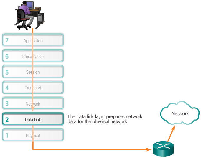
- The data link layer of the OSI model (Layer 2), as shown in Figure 1, is responsible for:
- Allowing the upper layers to access the media
- Accepting Layer 3 packets and packaging them into frames
- Preparing network data for the physical network
- Controlling how data is placed and received on the media
- Exchanging frames between nodes over a physical network media, such as UTP or fiber-optic
- Receiving and directing packets to an upper layer protocol
- Performing error detection
- The Layer 2 notation for network devices connected to a common media is called a node. Nodes build and forward frames. As shown in Figure 2, the OSI data link layer is responsible for the exchange of Ethernet frames between source and destination nodes over a physical network media. The data link layer effectively separates the media transitions that occur as the packet is forwarded from the communication processes of the higher layers. The data link layer receives packets from and directs packets to an upper layer protocol, in this case IPv4 or IPv6. This upper layer protocol does not need to be aware of which media the communication will use.
X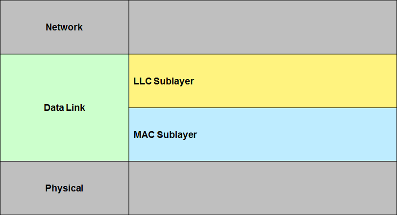
-
Providing Access to Media
- Different media access control methods may be required during a single communication. Each network environment that packets encounter as they travel from a local host to a remote host can have different characteristics. For example, an Ethernet LAN consists of many hosts contending to access the network medium. Serial links consist of a direct connection between only two devices. Router interfaces encapsulate the packet into the appropriate frame, and a suitable media access control method is used to access each link. In any given exchange of network layer packets, there may be numerous data link layers and media transitions. At each hop along the path, a router:
- Accepts a frame from a medium
- De-encapsulates the frame
- Re-encapsulates the packet into a new frame
- Forwards the new frame appropriate to the medium of that segment of the physical network
Data Link Layer Standards
- Unlike the protocols of the upper layers of the TCP/IP suite, data link layer protocols are generally not defined by Request for Comments (RFCs). Although the Internet Engineering Task Force (IETF) maintains the functional protocols and services for the TCP/IP protocol suite in the upper layers, the IETF does not define the functions and operation of that model's network access layer. Engineering organizations that define open standards and protocols that apply to the network access layer include:
- Institute of Electrical and Electronics Engineers (IEEE)
- International Telecommunication Union (ITU)
- International Organization for Standardization (ISO)
- American National Standards Institute (ANSI)
Standard organisation Networking Standards IEEE 802.2: Logical Link Control (LLC)
802.3: Ethernet
802.4: Token bus
802.5: Token passing
802.11: Wireless LAN (WLAN) & Mesh (Wi-Fi certification)
802.15: Bluetooth
802.16: WiMaxITU-T G.992: ADSL
G.8100 - G.8199: MPLS over Transport aspects
Q.921: ISDN
Q.922: Frame RelayISO HDLC (High Level Data Link Control)
ISO 9314: FDDI Media Access Control (MAC)ANSI X3T9.5 and X3T12: Fiber Distributed Data Interface (FDDI) -

Common Physical WAN Topologies
- WANs are commonly interconnected using the following physical topologies:
- Point-to-Point - This is the simplest topology that consists of a permanent link between two endpoints. For this reason, this is a very popular WAN topology.
- Hub and Spoke - A WAN version of the star topology in which a central site interconnects branch sites using point-to-point links.
- Mesh - This topology provides high availability, but requires that every end system be interconnected to every other system. Therefore the administrative and physical costs can be significant. Each link is essentially a point-to-point link to the other node. Variations of this topology include a partial mesh where some but not all of end devices are interconnected.
- The three common physical WAN topologies are illustrated in the 📷 figure.
Controlling Access to the Media
- Regulating the placement of data frames onto the media is controlled by the media access control sublayer. Media access control is the equivalent of traffic rules that regulate the entrance of motor vehicles onto a roadway. The absence of any media access control would be the equivalent of vehicles ignoring all other traffic and entering the road without regard to the other vehicles. However, not all roads and entrances are the same. Traffic can enter the road by merging, by waiting for its turn at a stop sign, or by obeying signal lights. A driver follows a different set of rules for each type of entrance. In the same way, there are different methods to regulate placing frames onto the media. The protocols at the data link layer define the rules for access to different media. These media access control techniques define if and how the nodes share the media. The actual media access control method used depends on:
- Topology - How the connection between the nodes appears to the data link layer.
- Media sharing - How the nodes share the media. The media sharing can be point-to-point, such as in WAN connections, or shared such as in LAN networks.
Physical and Logical Topologies
- The topology of a network is the arrangement or relationship of the network devices and the interconnections between them. LAN and WAN topologies can be viewed in two ways:
- Physical topology - Refers to the physical connections and identifies how end devices and infrastructure devices such as routers, switches, and wireless access points are interconnected. Physical topologies are usually point-to-point or star. See Figure 1.
- Logical topology - Refers to the way a network transfers frames from one node to the next. This arrangement consists of virtual connections between the nodes of a network. These logical signal paths are defined by data link layer protocols. The logical topology of point-to-point links is relatively simple while shared media offers different access control methods. See Figure 2.
- The data link layer "sees" the logical topology of a network when controlling data access to the media. It is the logical topology that influences the type of network framing and media access control used.
X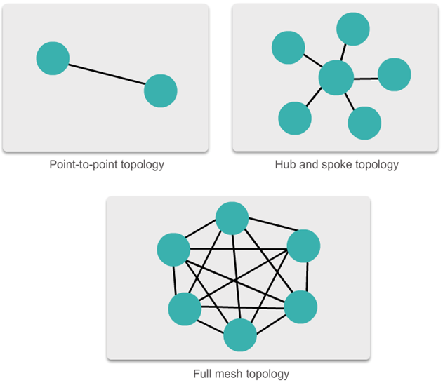
Half and Full Duplex
- Duplex communications refer to the direction of data transmission between two devices. Half-duplex communications restrict the exchange of data to one direction at a time while full-duplex allows the sending and receiving of data to happen simultaneously.
- Half-duplex communication - Both devices can transmit and receive on the media but cannot do so simultaneously. The half-duplex mode is used in legacy bus topologies and with Ethernet hubs. WLANs also operate in half-duplex. Half-duplex allows only one device to send or receive at a time on the shared medium and is used with contention-based access methods.
- Full-duplex communication - Both devices can transmit and receive on the media at the same time. The data link layer assumes that the media is available for transmission for both nodes at any time. Ethernet switches operate in full-duplex mode by default, but can operate in half-duplex if connecting to a device such as an Ethernet hub.
- It is important that two interconnected interfaces, such as a host’s NIC and an interface on an Ethernet switch operate using the same duplex mode. Otherwise, there will be a duplex mismatch creating inefficiency and latency on the link.
Physical Point-to-Point Topology
- Physical point-to-point topologies directly connect two nodes as shown in the 📷 figure. In this arrangement, two nodes do not have to share the media with other hosts. Additionally, a node does not have to make any determination about whether an incoming frame is destined for it or another node. Therefore, the logical data link protocols can be very simple, as all frames on the media can only travel to or from the two nodes. The frames are placed on the media by the node at one end and taken from the media by the node at the other end of the point-to-point circuit.
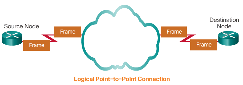
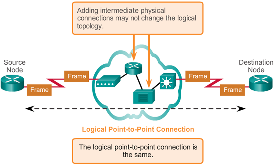
Logical Point-to-Point Topology
- The end nodes communicating in a point-to-point network can be physically connected via a number of intermediate devices. However, the use of physical devices in the network does not affect the logical topology. As shown in Figure 1, the source and destination node may be indirectly connected to each other over some geographical distance. In some cases, the logical connection between nodes forms what is called a virtual circuit. A virtual circuit is a logical connection created within a network between two network devices. The two nodes on either end of the virtual circuit exchange the frames with each other. This occurs even if the frames are directed through intermediary devices, as shown in Figure 2. Virtual circuits are important logical communication constructs used by some Layer 2 technologies. The media access method used by the data link protocol is determined by the logical point-to-point topology, not the physical topology. This means that the logical point-to-point connection between two nodes may not necessarily be between two physical nodes at each end of a single physical link.
X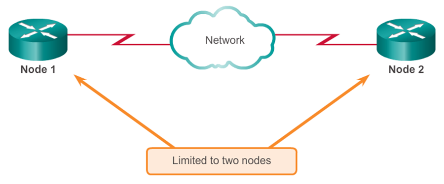
Contention-Based Access – CSMA/CD
- WLANs, Ethernet LANs with hubs, and legacy Ethernet bus networks are all examples of contention-based access networks. All of these networks operate in half-duplex mode. This requires a process to govern when a device can send and what happens when multiple devices send at the same time. The Carrier Sense Multiple Access/Collision Detection (CSMA/CD) process is used in half-duplex Ethernet LANs. Figure 1 shows an Ethernet LAN using a hub. The CSMA process is as follows: 1. PC1 has an Ethernet frame to send to PC3. 2. PC1’s NIC needs to determine if anyone is transmitting on the medium. If it does not detect a carrier signal, in other words, it is not receiving transmissions from another device, it will assume the network is available to send. 3. PC1’s NIC sends the Ethernet Frame. 4. The Ethernet hub receives the frame. An Ethernet hub is also known as a multiport repeater. Any bits received on an incoming port are regenerated and sent out all other ports. 5. If another device, such as PC2, wants to transmit, but is currently receiving a frame, it must wait until the channel is clear. 6. All devices attached to the hub will receive the frame. Because the frame has a destination data link address for PC3, only that device will accept and copy in the entire frame. All other devices’ NICs will ignore the frame. If two devices transmit at the same time, a collision will occur. Both devices will detect the collision on the network. This is done by the NIC comparing data transmitted with data received, or by recognizing the signal amplitude is higher than normal on the media. The data sent by both devices will be corrupted and will need to be resent.
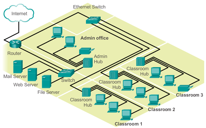
Physical LAN Topologies
- Physical topology defines how the end systems are physically interconnected. In shared media LANs, end devices can be interconnected using the following physical topologies:
- Star - End devices are connected to a central intermediate device. Early star topologies interconnected end devices using Ethernet hubs. However, star topologies now use Ethernet switches. The star topology is easy to install, very scalable (easy to add and remove end devices), and easy to troubleshoot.
- Extended Star - In an extended star topology, additional Ethernet switches interconnect other star topologies.
- Bus - All end systems are chained to each other and terminated in some form on each end. Infrastructure devices such as switches are not required to interconnect the end devices. Bus topologies using coax cables were used in legacy Ethernet networks because it was inexpensive and easy to set up.
- Ring - End systems are connected to their respective neighbor forming a ring. Unlike the bus topology, the ring does not need to be terminated. Ring topologies were used in legacy Fiber Distributed Data Interface (FDDI) and Token Ring networks.
- The 📷 figure illustrates how end devices are interconnected on LANs. It is common for a straight line in networking graphics to represent an Ethernet LAN including a simple star and an extended star.
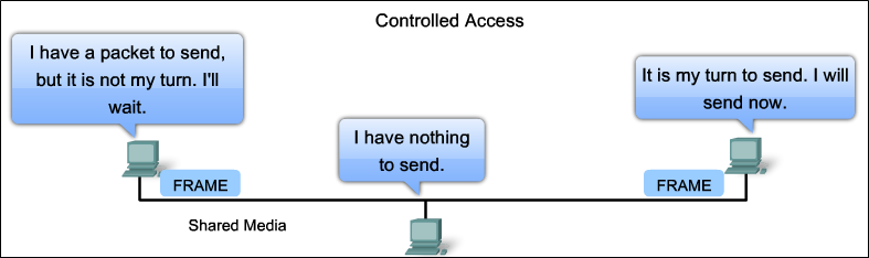
Media Access Control Methods
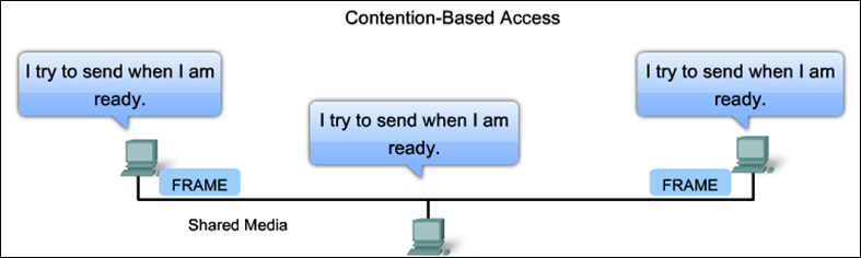
- Some network topologies share a common medium with multiple nodes. These are called multi-access networks. Ethernet LANs and WLANs are examples of a multi-access network. At any one time, there may be a number of devices attempting to send and receive data using the same network media. Some multi-access networks require rules to govern how devices share the physical media. There are two basic access control methods for shared media:
- Contention-based access - All nodes operating in half-duplex compete for the use of the medium, but only one device can send at a time. However, there is a process if more than one device transmits at the same time. Ethernet LANs using hubs and WLANs are examples of this type of access control. Figure 1 shows contention-based access.
- Controlled access - Each node has its own time to use the medium. These deterministic types of networks are inefficient because a device must wait its turn to access the medium. Legacy Token Ring LANs are an example of this type of access control. Figure 2 shows controlled access. Refer to the Chapter Appendix to learn more about controlled access.
- By default, Ethernet switches operate in full-duplex mode. This allows the switch and the full-duplex connected device to send and receive simultaneously.
X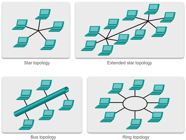
Data Link Frame
The Frame
- The data link layer prepares a packet for transport across the local media by encapsulating it with a header and a trailer to create a frame. The description of a frame is a key element of each data link layer protocol. Although there are many different data link layer protocols that describe data link layer frames, each frame type has three basic parts:
- Header
- Data
- Trailer
- All data link layer protocols encapsulate the Layer 3 PDU within the data field of the frame. However, the structure of the frame and the fields contained in the header and trailer vary according to the protocol. There is no one frame structure that meets the needs of all data transportation across all types of media. Depending on the environment, the amount of control information needed in the frame varies to match the access control requirements of the media and logical topology.
- As shown in the 📷 figure, a fragile environment requires more control.
Frame Fields
- Framing breaks the stream into decipherable groupings, with control information inserted in the header and trailer as values in different fields. This format gives the physical signals a structure that can be received by nodes and decoded into packets at the destination. As shown in the 📷 figure, generic frame field types include:
- Frame start and stop indicator flags - Used to identify the beginning and end limits of the frame.
- Addressing - Indicates the source and destination nodes on the media.
- Type - Identifies the Layer 3 protocol in the data field.
- Control - Identifies special flow control services such as quality of service (QoS). QoS is used to give forwarding priority to certain types of messages. Data link frames carrying voice over IP (VoIP) packets normally receive priority because they are sensitive to delay.
- Data - Contains the frame payload (i.e., packet header, segment header, and the data).
- Error Detection - These frame fields are used for error detection and are included after the data to form the trailer.
- Not all protocols include all of these fields. The standards for a specific data link protocol define the actual frame format. Data link layer protocols add a trailer to the end of each frame. The trailer is used to determine if the frame arrived without error. This process is called error detection and is accomplished by placing a logical or mathematical summary of the bits that comprise the frame in the trailer. Error detection is added at the data link layer because the signals on the media could be subject to interference, distortion, or loss that would substantially change the bit values that those signals represent. A transmitting node creates a logical summary of the contents of the frame, known as the cyclic redundancy check (CRC) value. This value is placed in the Frame Check Sequence (FCS) field to represent the contents of the frame. In the Ethernet trailer, the FCS provides a method for the receiving node to determine whether the frame experienced transmission errors. Refer to the Chapter Appendix to learn more about the frame trailer.
X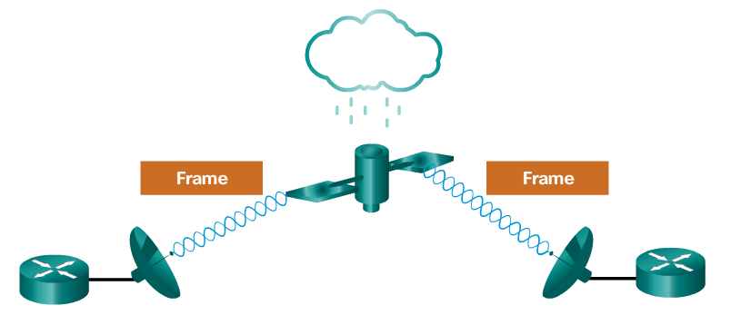 X
X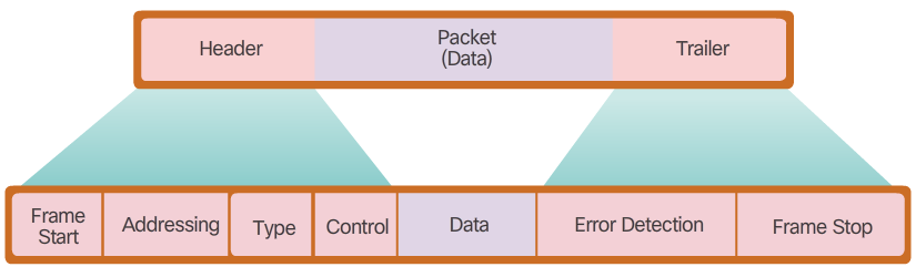
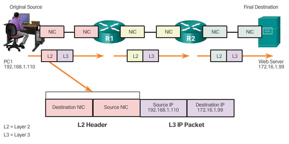
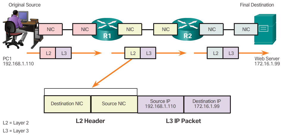
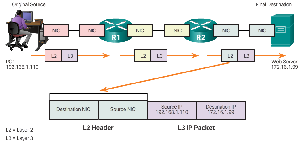
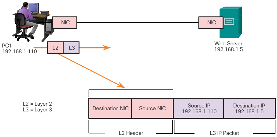
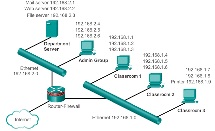
Layer 2 Address
- The data link layer provides addressing that is used in transporting a frame across a shared local media. Device addresses at this layer are referred to as physical addresses. Data link layer addressing is contained within the frame header and specifies the frame destination node on the local network. The frame header may also contain the source address of the frame. Unlike Layer 3 logical addresses, which are hierarchical, physical addresses do not indicate on what network the device is located. Rather, the physical address is unique to the specific device. If the device is moved to another network or subnet, it will still function with the same Layer 2 physical address. Figures 1 through 3 illustrate the function of the Layer 2 and Layer 3 addresses. As the IP packet travels from host-to-router, router-to-router, and finally router-to-host, at each point along the way the IP packet is encapsulated in a new data link frame. Each data link frame contains the source data link address of the NIC card sending the frame, and the destination data link address of the NIC card receiving the frame. An address that is device-specific and non-hierarchical cannot be used to locate a device on large networks or the Internet. This would be like trying to find a single house within the entire world, with nothing more than a house number and street name. The physical address, however, can be used to locate a device within a limited area. For this reason, the data link layer address is only used for local delivery. Addresses at this layer have no meaning beyond the local network. Compare this to Layer 3, where addresses in the packet header are carried from the source host to the destination host, regardless of the number of network hops along the route. If the data must pass onto another network segment, an intermediate device, such as a router, is necessary. The router must accept the frame based on the physical address and de-encapsulate the frame in order to examine the hierarchical address, or IP address. Using the IP address, the router is able to determine the network location of the destination device and the best path to reach it. When it knows where to forward the packet, the router then creates a new frame for the packet, and the new frame is sent on to the next network segment toward its final destination.
LAN and WAN Frames
- In a TCP/IP network, all OSI Layer 2 protocols work with IP at OSI Layer 3. However, the Layer 2 protocol used depends on the logical topology and the physical media. Each protocol performs media access control for specified Layer 2 logical topologies. This means that a number of different network devices can act as nodes that operate at the data link layer when implementing these protocols. These devices include the NICs on computers as well as the interfaces on routers and Layer 2 switches. The Layer 2 protocol used for a particular network topology is determined by the technology used to implement that topology. The technology is, in turn, determined by the size of the network - in terms of the number of hosts and the geographic scope - and the services to be provided over the network. A LAN typically uses a high bandwidth technology that is capable of supporting large numbers of hosts. A LAN's relatively small geographic area (a single building or a multi-building campus) and its high density of users, make this technology cost-effective. However, using a high bandwidth technology is usually not cost-effective for WANs that cover large geographic areas (cities or multiple cities, for example). The cost of the long distance physical links and the technology used to carry the signals over those distances typically results in lower bandwidth capacity. The difference in bandwidth normally results in the use of different protocols for LANs and WANs. Data link layer protocols include:
- 📷 Ethernet
- 📷 802.11 Wireless
- 📷 Point-to-Point Protocol (PPP)
- HDLC
- Frame Relay
X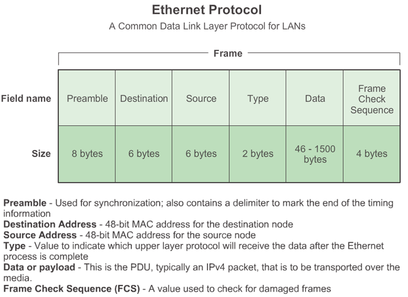 X
X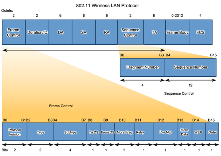 X
X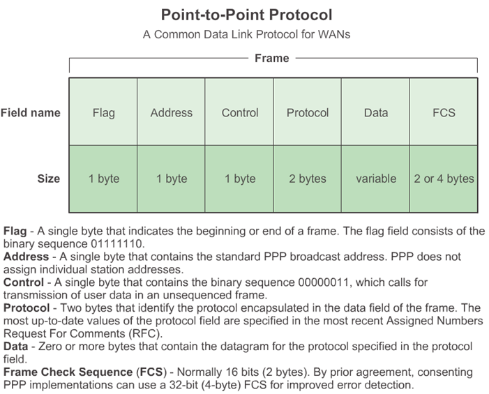
Summary
- The TCP/IP network access layer is the equivalent of the OSI data link layer (Layer 2) and the physical layer (Layer 1).
- The OSI physical layer provides the means to transport the bits that make up a data link layer frame across the network media.
- The physical layer standards address three functional areas: physical components, frame encoding technique, and signaling method.
- Using the proper media is an important part of network communications. Without the proper physical connection, either wired or wireless, communications between any two devices will not occur.
- Wired communication consists of copper media and fiber cable.
- There are three main types of copper media used in networking: unshielded-twisted pair (UTP), shielded-twisted pair (STP), and coaxial cable. UTP cabling is the most common copper networking media.
- Optical fiber cable has become very popular for interconnecting infrastructure network devices. It permits the transmission of data over longer distances and at higher bandwidths (data rates) than any other networking media.
- Wireless media carry electromagnetic signals that represent the binary digits of data communications using radio or microwave frequencies.
- The data link layer is responsible for the exchange of frames between nodes over a physical network media. It allows the upper layers to access the media and controls how data is placed and received on the media.
- Among the different implementations of the data link layer protocols, there are different methods of controlling access to the media. These media access control techniques define if and how the nodes share the media.
- The actual media access control method used depends on the topology and media sharing. LAN and WAN topologies can be physical or logical.
- WANs are commonly interconnected using the point-to-point, hub and spoke, or mesh physical topologies.
- In shared media LANs, end devices can be interconnected using the star, bus, ring, or extended star (hybrid) physical topologies.
- All data link layer protocols encapsulate the Layer 3 PDU within the data field of the frame. However, the structure of the frame and the fields contained in the header and trailer vary according to the protocol.