-

Chapter 6: Objectives
- In this chapter, you will be able to:
- Explain how network layer protocols and services support communications across data networks.
- Explain how routers enable end-to-end connectivity in a small-to-medium-sized business network.
- Determine the appropriate device to route traffic in a small-to-medium-sized business network.
- Configure a router with basic configurations.
Chapter 6
- Network Layer Protocols
- Routing
- Routers
- Configuring a Cisco Router
- Summary
-

Encapsulating IP
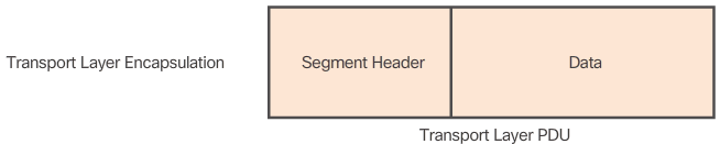
- The transport layer adds a header so segments can be reassembled at the destination
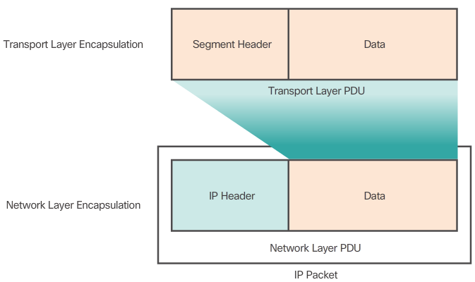
- The network layer adds a header so packets can be routed through complex networks and reach their destination. In TCP/ip based networks, the network layer PDU is the IP Packet.
- IP encapsulates the transport layer segment by adding an IP header. This header is used to deliver the packet to the destination host. The IP header remains in place from the time the packet leaves the source host until it arrives at the destination host. Figure 1 shows the process to create the transport layer PDU. Figure 2 illustrates how the transport layer PDU is then encapsulated by the network layer PDU to create an IP packet. The process of encapsulating data layer by layer enables the services at the different layers to develop and scale without affecting the other layers. This means the transport layer segments can be readily packaged by IPv4 or IPv6 or by any new protocol that might be developed in the future. Routers can implement these different network layer protocols to operate concurrently over a network. The routing performed by these intermediate devices only considers the contents of the network layer packet header. In all cases, the data portion of the packet, that is, the encapsulated transport layer PDU, remains unchanged during the network layer processes.
The Network Layer
- The network layer, or OSI Layer 3, provides services to allow end devices to exchange data across the network. To accomplish this end-to-end transport, the network layer uses four basic processes:
- Addressing end devices - End devices must be configured with a unique IP address for identification on the network.
- Encapsulation - The network layer encapsulates the protocol data unit (PDU) from the transport layer into a packet. The encapsulation process adds IP header information, such as the IP address of the source (sending) and destination (receiving) hosts.
- Routing - The network layer provides services to direct packets to a destination host on another network. To travel to other networks, the packet must be processed by a router. The role of the router is to select the best path and direct packets toward the destination host in a process known as routing. A packet may cross many intermediary devices before reaching the destination host. Each router a packet crosses to reach the destination host is called a hop.
- De-encapsulation - When the packet arrives at the network layer of the destination host, the host checks the IP header of the packet. If the destination IP address within the header matches its own IP address, the IP header is removed from the packet. After the packet is de-encapsulated by the network layer, the resulting Layer 4 PDU is passed up to the appropriate service at the transport layer.
- Unlike the transport layer (OSI Layer 4), which manages the data transport between the processes running on each host, network layer protocols specify the packet structure and processing used to carry the data from one host to another host. Operating without regard to the data carried in each packet allows the network layer to carry packets for multiple types of communications between multiple hosts.
Network Layer Protocols
- There are several network layer protocols in existence. However, only the following two are commonly implemented:
- Internet Protocol version 4 (IPv4)
- Internet Protocol version 6 (IPv6)
- Note: Legacy network layer protocols are not shown in the 📷 figure and are not discussed in this course.
X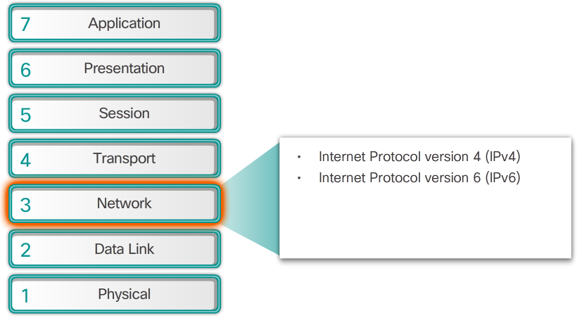
-
IP - Best Effort Delivery
- The 📷 figure illustrates the unreliable or best-effort delivery characteristic of the IP protocol. The IP protocol does not guarantee that all packets that are delivered are, in fact, received.
- Unreliable means that IP does not have the capability to manage and recover from undelivered or corrupt packets. This is because while IP packets are sent with information about the location of delivery, they contain no information that can be processed to inform the sender whether delivery was successful. Packets may arrive at the destination corrupted, out of sequence, or not at all. IP provides no capability for packet retransmissions if errors occur.
- If out-of-order packets are delivered, or packets are missing, then applications using the data, or upper layer services, must resolve these issues. This allows IP to function very efficiently. In the TCP/IP protocol suite, reliability is the role of the transport layer.
IP - Media Independent
- IP operates independently of the media that carry the data at lower layers of the protocol stack. As shown in the 📷 figure, IP packets can be communicated as electronic signals over copper cable, as optical signals over fiber, or wirelessly as radio signals.
- It is the responsibility of the OSI data link layer to take an IP packet and prepare it for transmission over the communications medium. This means that the transport of IP packets is not limited to any particular medium.
- There is, however, one major characteristic of the media that the network layer considers: the maximum size of the PDU that each medium can transport. This characteristic is referred to as the maximum transmission unit (MTU). Part of the control communication between the data link layer and the network layer is the establishment of a maximum size for the packet. The data link layer passes the MTU value up to the network layer. The network layer then determines how large packets can be.
- In some cases, an intermediate device, usually a router, must split up a packet when forwarding it from one medium to another medium with a smaller MTU. This process is called fragmenting the packet or fragmentation.
IP - Connectionless
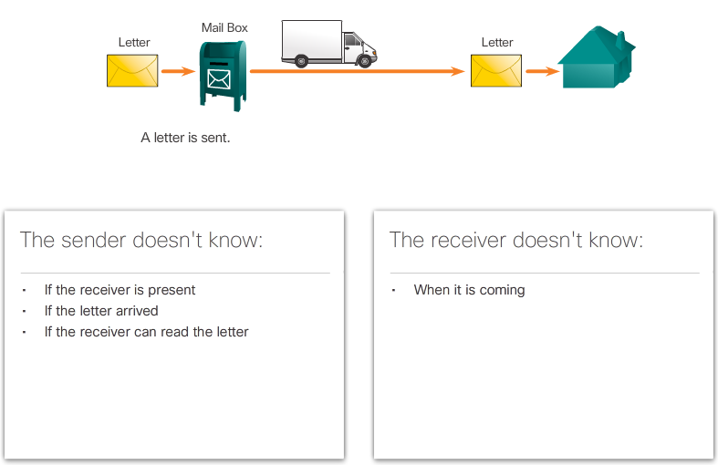
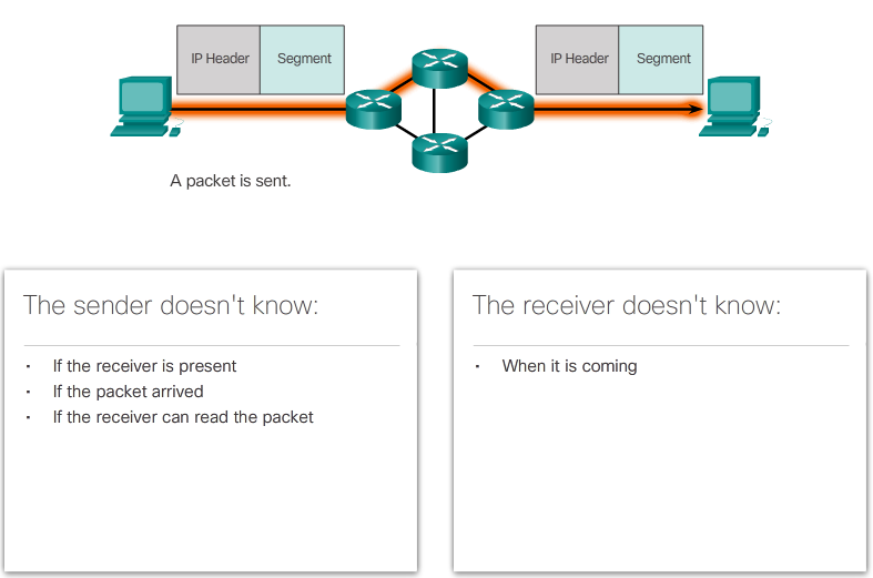
- IP is connectionless, meaning that no dedicated end-to-end connection is created before data is sent. As shown in Figure 1, connectionless communication is conceptually similar to sending a letter to someone without notifying the recipient in advance.
- Connectionless data communications work on the same principle. As shown in Figure 2, IP requires no initial exchange of control information to establish an end-to-end connection before packets are forwarded. IP also does not require additional fields in the header to maintain an established connection. This process greatly reduces the overhead of IP. However, with no pre-established end-to-end connection, senders are unaware whether destination devices are present and functional when sending packets, nor are they aware if the destination receives the packet, or if they are able to access and read the packet.
X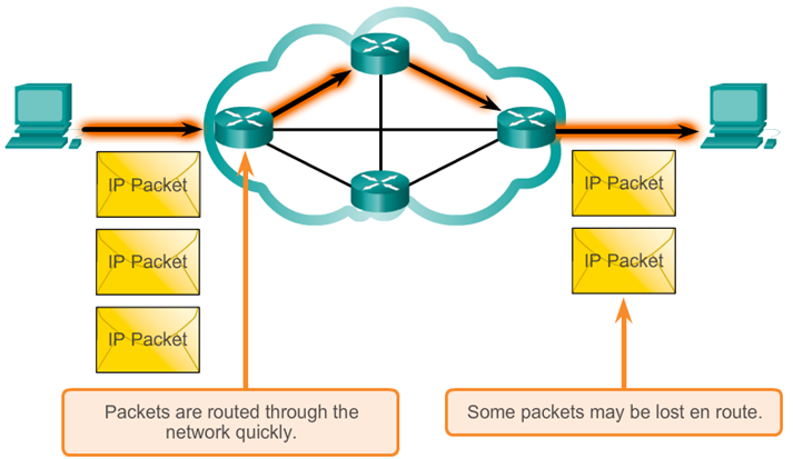 X
X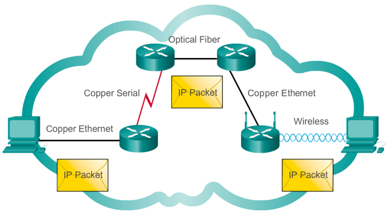
-
Limitations of IPv4
- Through the years, IPv4 has been updated to address new challenges. However, even with changes, IPv4 still has three major issues:
- IP address depletion - IPv4 has a limited number of unique public IPv4 addresses available. Although there are approximately 4 billion IPv4 addresses, the increasing number of new IP-enabled devices, always-on connections, and the potential growth of less-developed regions have increased the need for more addresses.
- Internet routing table expansion - A routing table is used by routers to make best path determinations. As the number of servers connected to the Internet increases, so too does the number of network routes. These IPv4 routes consume a great deal of memory and processor resources on Internet routers.
- Lack of end-to-end connectivity - Network Address Translation (NAT) is a technology commonly implemented within IPv4 networks. NAT provides a way for multiple devices to share a single public IPv4 address. However, because the public IPv4 address is shared, the IPv4 address of an internal network host is hidden. This can be problematic for technologies that require end-to-end connectivity.
IPv4 Packet Header
- An IPv4 packet header consists of fields containing important information about the packet. These fields contain binary numbers which are examined by the Layer 3 process. The binary values of each field identify various settings of the IP packet. Protocol header diagrams, like the one shown in the 📷 figure, are read left to right, and top down.
- Significant fields in the IPv4 header include:
- Version - Contains a 4-bit binary value set to 0100 that identifies this as an IP version 4 packet.
- Differentiated Services (DS) - Formerly called the Type of Service (ToS) field, the DS field is an 8-bit field used to determine the priority of each packet.
- Time-to-Live (TTL) - Contains an 8-bit binary value that is used to limit the lifetime of a packet. The packet sender sets the initial TTL value, and it is decreased by one each time the packet is processed by a router. If the TTL field decrements to zero, the router discards the packet and sends an Internet Control Message Protocol (ICMP) Time Exceeded message to the source IP address.
- Protocol - This 8-bit binary value indicates the data payload type that the packet is carrying, which enables the network layer to pass the data to the appropriate upper-layer protocol. Common values include ICMP (1), TCP (6), and UDP (17).
- Source IP Address - Contains a 32-bit binary value that represents the source IP address of the packet.
- Destination IP Address - Contains a 32-bit binary value that represents the destination IP address of the packet.
- The two most commonly referenced fields are the source and destination IP addresses. These fields identify where the packet is coming from and where it is going. Typically these addresses do not change while travelling from the source to the destination.
- The Internet Header Length (IHL), Total Length, and Header Checksum fields are used to identify and validate the packet.
- Other fields are used to reorder a fragmented packet. Specifically, the IPv4 packet uses Identification, Flags, and Fragment Offset fields to keep track of the fragments. A router may have to fragment a packet when forwarding it from one medium to another with a smaller MTU.
- The Options and Padding fields are rarely used and are beyond the scope of this chapter.
- 📷 IPv4 Header Fields
- 📷 Sample IPv4 Headers
X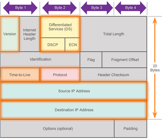 X
X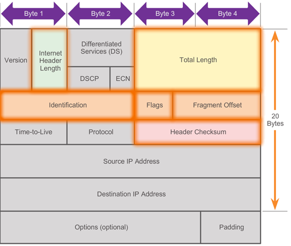 X
X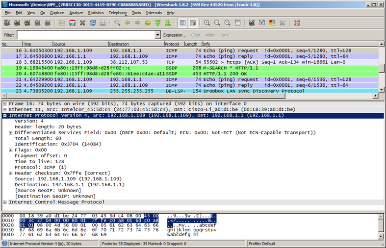
-
- IPv6 Advantages Include
- Simplified header format for efficient packet handling
- Larger payload for increased throughput and transport efficiency
- Hierarchical network architecture for routing efficiency
- Autoconfiguration for address
- Elimination of need for netwrok address translation (NAT) between private and public addresses
- 📷 IPv6 Packet Header
- 📷 Sample IPv6 Header
Introducing IPv6
- In the early 1990s, the Internet Engineering Task Force (IETF) grew concerned about the issues with IPv4 and began to look for a replacement. This activity led to the development of IP version 6 (IPv6). IPv6 overcomes the limitations of IPv4 and is a powerful enhancement with features that better suit current and foreseeable network demands.
- Improvements that IPv6 provides include:
- Increased address space - IPv6 addresses are based on 128-bit hierarchical addressing as opposed to IPv4 with 32 bits.
- Improved packet handling - The IPv6 header has been simplified with fewer fields.
- Eliminates the need for NAT - With such a large number of public IPv6 addresses, NAT between a private IPv4 address and a public IPv4 is not needed. This avoids some of the NAT-induced application problems experienced by applications requiring end-to-end connectivity.
- The 32-bit IPv4 address space provides approximately 4,294,967,296 unique addresses. IPv6 address space provides 340,282,366,920,938,463,463,374,607,431,768,211,456, or 340 undecillion addresses, which is roughly equivalent to every grain of sand on Earth.
Encapsulating IPv6
- One of the major design improvements of IPv6 over IPv4 is the simplified IPv6 header.
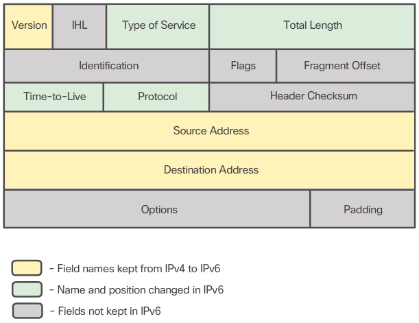
- For instance, the IPv4 header shown in Figure 1 consists of 20 octets (up to 60 bytes if the Options field is used) and 12 basic header fields, not including the Options field and Padding field. As highlighted in the figure, for IPv6, some fields have remained the same, some fields have changed names and positions, and some IPv4 fields are no longer required.
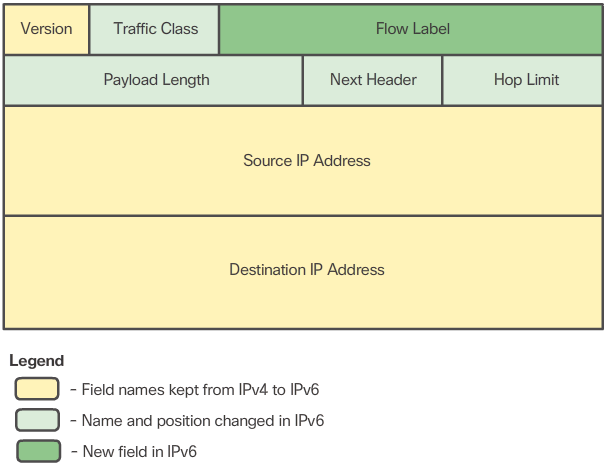
- In contrast, the simplified IPv6 header shown in Figure 2 consists of 40 octets (largely due to the length of the source and destination IPv6 addresses) and 8 header fields (3 IPv4 basic header fields and 5 additional header fields). As highlighted in this figure, some fields have kept the same names as IPv4, some fields have changed names or positions, and a new field has been added.
- The IPv6 simplified header offers several advantages over IPv4 as listed in Figure 3.
X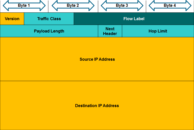 X
X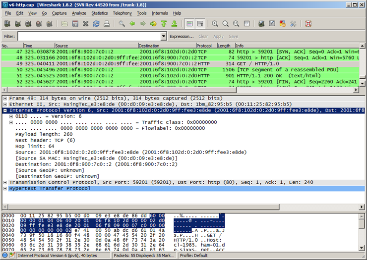
-

Default Gateway
- The default gateway is the network device that can route traffic to other networks. It is the router that can route traffic out of the local network.
- If you use the analogy that a network is like a room, then the default gateway is like a doorway. If you want to get to another room or network you need to find the doorway.
- Alternatively, a PC or computer that does not know the IP address of the default gateway is like a person, in a room, that does not know where the doorway is. They can talk to other people in the room or network, but if they do not know the default gateway address, or there is no default gateway, then there is no way out.
Host Routing Tables
- On a Windows host, the route print or netstat -r command can be used to display the host routing table. Both commands generate the same output. The output may seem overwhelming at first, but is fairly simple to understand.
- Entering the netstat -r command or the equivalent route print command, displays three sections related to the current TCP/IP network connections:
- Interface List - Lists the Media Access Control (MAC) address and assigned interface number of every network-capable interface on the host, including Ethernet, Wi-Fi, and Bluetooth adapters.
- IPv4 Route Table - Lists all known IPv4 routes, including direct connections, local network, and local default routes.
- IPv6 Route Table - Lists all known IPv6 routes, including direct connections, local network, and local default routes.
- 📷 IPv4 Routing Table for PC1
- 📷 Sample IPv4 Routing Table
- 📷 Sample IPv6 Host Routing Table
Host Forwarding Decision
- Another role of the network layer is to direct packets between hosts. A host can send a packet to:
- Itself - A host can ping itself by sending a packet to a special IPv4 address of 127.0.0.1, which is referred to as the loopback interface. Pinging the loopback interface tests the TCP/IP protocol stack on the host.
- Local host - This is a host on the same local network as the sending host. The hosts share the same network address.
- Remote host - This is a host on a remote network. The hosts do not share the same network address.
- Whether a packet is destined for a local host or a remote host is determined by the IPv4 address and subnet mask combination of the source (or sending) device compared to the IPv4 address and subnet mask of the destination device.
- In a home or business network, you may have several wired and wireless devices interconnected together using an intermediate device, such as a LAN switch and/or a wireless access point (WAP). This intermediate device provides interconnections between local hosts on the local network. Local hosts can reach each other and share information without the need for any additional devices. If a host is sending a packet to a device that is configured with the same IP network as the host device, the packet is simply forwarded out of the host interface, through the intermediate device, and to the destination device directly.
- Of course, in most situations we want our devices to be able to connect beyond the local network segment, such as out to other homes, businesses, and the Internet. Devices that are beyond the local network segment are known as remote hosts. When a source device sends a packet to a remote destination device, then the help of routers and routing is needed. Routing is the process of identifying the best path to a destination. The router connected to the local network segment is referred to as the default gateway.
X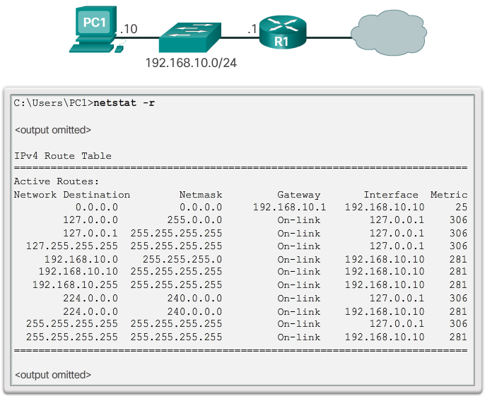 X
X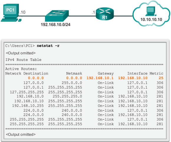 X
X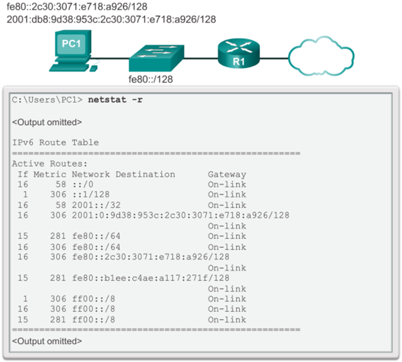
-
Directly Connected Routing Table Entries
- When a router interface is configured with an IPv4 address, a subnet mask, and is activated, the following two routing table entries are automatically created:
- C - Identifies a directly-connected network. Directly-connected networks are automatically created when an interface is configured with an IP address and activated.
- L - Identifies that this is a local interface. This is the IPv4 address of the interface on the router.
- The 📷 figure describes the routing table entries on R1 for the directly-connected network 192.168.10.0. These entries were automatically added to the routing table when the GigabitEthernet 0/0 interface was configured and activated. Click each plus sign to view more information about directly-connected routing table entries.
- Note: Local interface entries did not appear in routing tables prior to IOS Release 15.
Remote Network Routing Table Entries
- A router typically has multiple interfaces configured. The routing table stores information about both directly-connected networks and remote networks.
- The 📷 figure describes the R1 route to remote network 10.1.1.0.
Router Packet Forwarding Decision
- When a host sends a packet to another host, it will use its routing table to determine where to send the packet. If the destination host is on a remote network, the packet is forwarded to the default gateway.
- What happens when a packet arrives at the default gateway, which is usually a router? The router looks at its routing table to determine where to forward packets.
- The routing table of a router can store information about:
- Directly-connected routes - These routes come from the active router interfaces. Routers add a directly connected route when an interface is configured with an IP address and is activated. Each of the router's interfaces is connected to a different network segment.
- Remote routes - These routes come from remote networks connected to other routers. Routes to these networks can be manually configured on the local router by the network administrator or dynamically configured by enabling the local router to exchange routing information with other routers using a dynamic routing protocol.
- Default route – Like a host, routers also use a default route as a last resort if there is no other route to the desired network in the routing table.
- The 📷 figure identifies the directly connected networks and remote networks of router R1.
IPv4 Router Routing Table
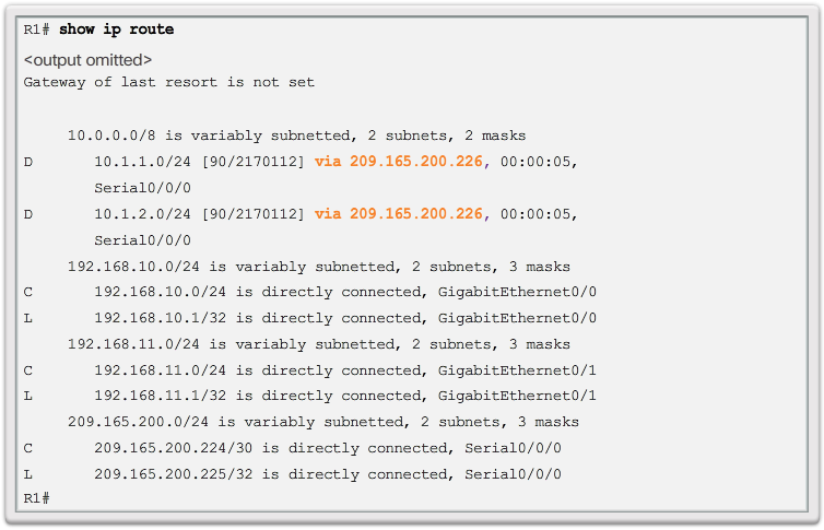
- On a Cisco IOS router, the show ip route command can be used to display the router’s routing table, as shown in the 📷 figure.
- In addition to providing routing information for directly-connected networks and remote networks, the routing table also has information on how the route was learned, the trustworthiness and rating of the route, when the route was last updated, and which interface to use to reach the requested destination.
- When a packet arrives at the router interface, the router examines the packet header to determine the destination network. If the destination network matches a route in the routing table, the router forwards the packet using the information specified in the routing table. If there are two or more possible routes to the same destination, the metric is used to decide which route appears in the routing table.
- The 📷 figure shows the routing table of R1 depicted in the network diagram.
X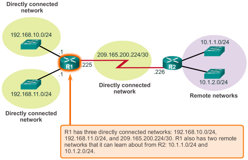 X
X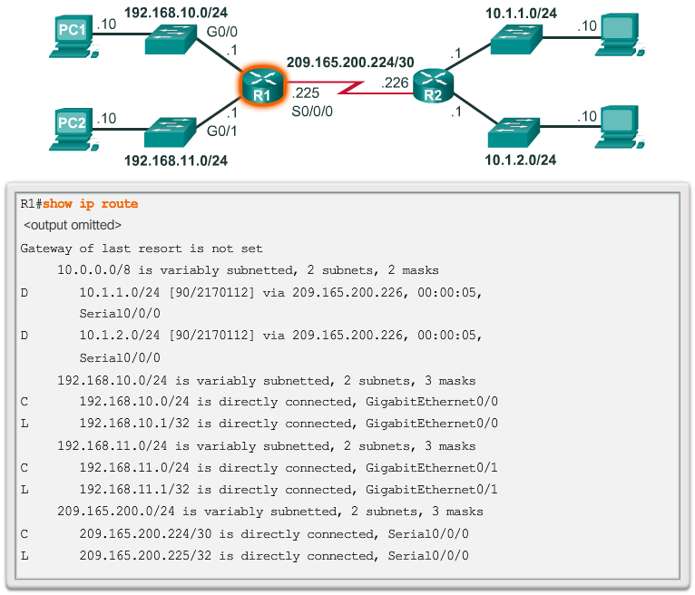 X
X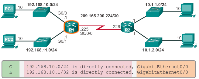 X
X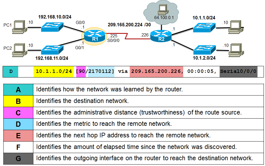
-
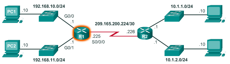
Next-Hop Address
- When a packet destined for a remote network arrives at the router, the router matches the destination network to a route in the routing table. If a match is found, the router forwards the packet to the next hop address out of the identified interface.
- Refer to the sample network topology in Figure 1. Assume that either PC1 or PC2 has sent a packet destined for either the 10.1.1.0 or 10.1.2.0 network. When the packet arrives on the R1 Gigabit interface, R1 will compare the packet’s destination IPv4 address to entries in its routing table. The routing table is displayed in Figure 2. Based on the content of its routing, R1 will forward the packet out of its Serial 0/0/0 interface to the next hop address 209.165.200.226.
- Notice how directly connected networks with a route source of C and L have no next-hop address. This is because a router can forward packets directly to hosts on these networks using the designated interface.
- It is also important to understand that packets cannot be forwarded by the router without a route for the destination network in the routing table. If a route representing the destination network is not in the routing table, the packet is dropped (that is, not forwarded). However, just as a host can use a default gateway to forward a packet to an unknown destination, a router can also be configured to use a default static route to create a Gateway of Last Resort.
-

Router Memory
- A router has access to volatile or non-volatile memory storage. Volatile memory requires continual power to maintain its information. When the router is powered down or restarted, the content is erased and lost. Non-volatile memory retains its information even when a device is rebooted.
- Specifically, Cisco router uses four types of memory:
- RAM - This is volatile memory used in Cisco routers to store applications, processes, and data needed to be executed by the CPU. Cisco routers use a fast type of RAM called synchronous dynamic random access memory (SDRAM).
- ROM - This non-volatile memory is used to store crucial operational instructions and a limited IOS. Specifically, ROM is firmware embedded on an integrated circuit inside the router which can only be altered by Cisco.
- NVRAM - This memory is used as the permanent storage for the startup configuration file (startup-config).
- Flash - Flash memory is non-volatile computer memory used as permanent storage for the IOS and other system related files such as log files, voice configuration files, HTML files, backup configurations, and more. When a router is rebooted, the IOS is copied from flash into RAM.
- All router platforms have default settings and components. For instance, the Cisco 1941 comes with 512 MB of SDRAM but is upgradable up to 2.0 GB. The Cisco 1941 routers also come with 256 MB of flash but are upgradable using two external Compact Flash slots. Each slot can support high-speed storage cards upgradable to 4GB. Click here to learn more about the Cisco 1941 Integrated Services Router.
A Router is a Computer
- There are many types of infrastructure routers available. In fact, Cisco routers are designed to address the needs of many different types of businesses and networks:
- Branch - Teleworkers, small businesses, and medium-size branch sites. Includes Cisco Integrated Services Routers (ISR) G2 (2nd generation).
- WAN - Large businesses, organizations, and enterprises. Includes the Cisco Catalyst Series Switches and the Cisco Aggregation Services Routers (ASR).
- Service Provider - Large service providers. Includes Cisco ASR, Cisco CRS-3 Carrier Routing System, and 7600 Series routers.
- The focus of CCNA certification is on the branch family of routers. The 📷 figure displays the Cisco 1900, 2900, and 3900 G2 Integrated Services Routers.
- Regardless of their function, size or complexity, all router models are essentially computers. Just like computers, tablets, and smart devices, routers also require:
- Central processing units (CPU)
- Operating systems (OS)
- Memory consisting of random-access memory (RAM), read-only memory (ROM), nonvolatile random-access memory (NVRAM), and flash.
Router CPU and OS
- Like all computers, tablets, gaming consoles, and smart devices, Cisco devices require a CPU to execute OS instructions, such as system initialization, routing functions, and switching functions.
- The highlighted component in the 📷 figure is the CPU of a Cisco 1941 router with the heatsink attached. The heatsink helps dissipate the heat generated by the CPU.
- The CPU requires an OS to provide routing and switching functions. The Cisco Internetwork Operating System (IOS) is the system software used for most Cisco devices regardless of the size and type of the device. It is used for routers, LAN switches, small wireless access points, large routers with dozens of interfaces, and many other devices.
X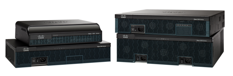 X
X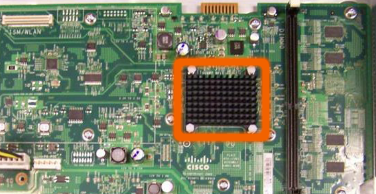
-
Inside a Router
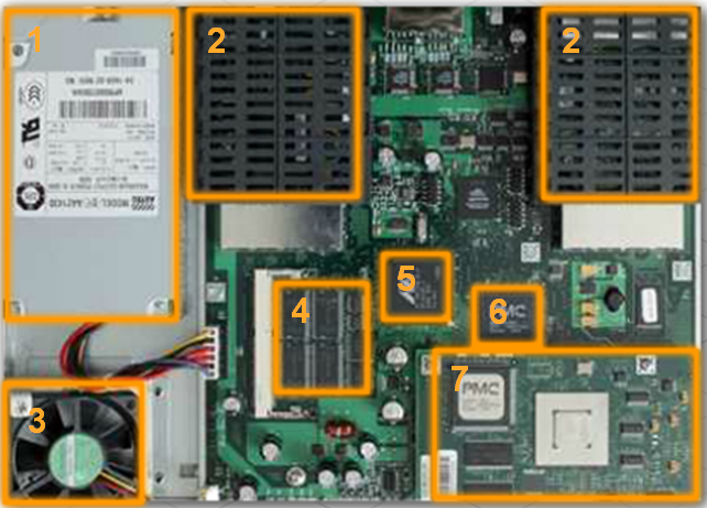
- 1. PowerSupply
- 2. Shield for WIC
- 3. Fan
- 4. SDRAM
- 5. NVRAM
- 6. CPU
- 7Advanced Integration Module (AIM)
Connect to a Router
- Cisco devices, routers, and switches typically interconnect many devices. For this reason, these devices have several types of ports and interfaces that are used to connect to the device. For example, a Cisco 1941 router backplane includes the connections and ports described in the 📷 figure.
- Like many networking devices, Cisco devices use light emitting diode (LED) indicators to provide status information. An interface LED indicates the activity of the corresponding interface. If an LED is off when the interface is active, and the interface is correctly connected, this may be an indication of a problem with that interface. If an interface is extremely busy, its LED is always on.
LAN and WAN Interfaces
- The connections on a Cisco router can be grouped into two categories: In-band router interfaces and management ports.
- Similar to a Cisco switch, there are several ways to access user EXEC mode in the CLI environment on a Cisco router. These are the most common:
- Console – This is a physical management port that provides out-of-band access to a Cisco device. Out-of-band access refers to access via a dedicated management channel that is used for device maintenance purposes only.
- Secure Shell (SSH) – SSH is a method for remotely establishing a secure CLI connection through a virtual interface, over a network. Unlike a console connection, SSH connections require active networking services on the device including an active interface configured with an address.
- Telnet - Telnet is an insecure method of remotely establishing a CLI session through a virtual interface, over a network. Unlike SSH, Telnet does not provide a securely encrypted connection. User authentication, passwords, and commands are sent over the network in plaintext.
- Note: Some devices, such as routers, may also support a legacy auxiliary port that was used to establish a CLI session remotely using a modem. Similar to a console connection, the AUX port is out-of-band and does not require networking services to be configured or available.
- Telnet and SSH require an inband network connection which means that an administrator must access the router through one of the WAN or LAN interfaces.
- Inband interfaces receive and forward IP packets. Every configured and active interface on the router is a member or host on a different IP network. Each interface must be configured with an IPv4 address and subnet mask of a different network. The Cisco IOS does not allow two active interfaces on the same router to belong to the same network.
X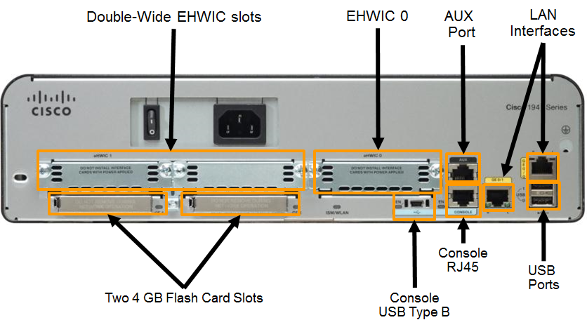
-
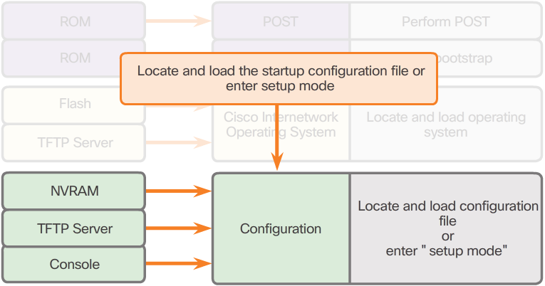
Router Bootup Process cont...
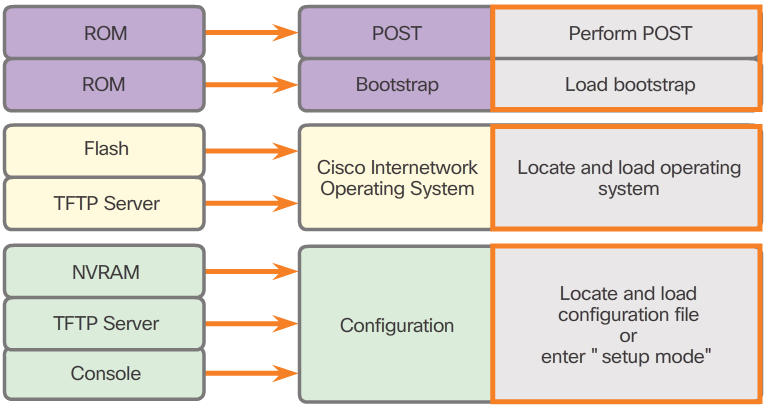
- 3. Locating and Loading the Configuration File (Figure 4)
- The bootstrap program then copies the startup configuration file from NVRAM into RAM. This becomes the running configuration. If the startup configuration file does not exist in NVRAM, the router may be configured to search for a TFTP server. If a TFTP server is not found, then the router displays the setup mode prompt.
- Note: Setup mode is not used in this course to configure the router. When prompted to enter setup mode, always answer no. If you answer yes and enter setup mode, press Ctrl+C at any time to terminate the setup process.
Show Version Output
- As highlighted in the 📷 figure, the show version command displays information about the version of the Cisco IOS software currently running on the router, the version of the bootstrap program, and information about the hardware configuration, including the amount of system memory.
Cisco IOS
- The Cisco IOS operational details vary on different internetworking devices, depending on the device’s purpose and feature set. However, Cisco IOS for routers provides the following:
- Addressing
- Interfaces
- Routing
- Security
- QoS
- Resources Management
Bootset Files
- Both Cisco routers and switches load the IOS image and startup configuration file into RAM when they are booted, as shown in the 📷 figure.
- The running configuration is modified when the network administrator performs device configurations. Changes made to the running-config file should be saved to the startup configuration file in NVRAM, in case the router is restarted or loses power.
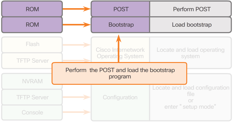
Router Bootup Process
- There are three major phases to the bootup process. As shown in Figure 1, they are:
- 1. Perform the POST and load the bootstrap program.
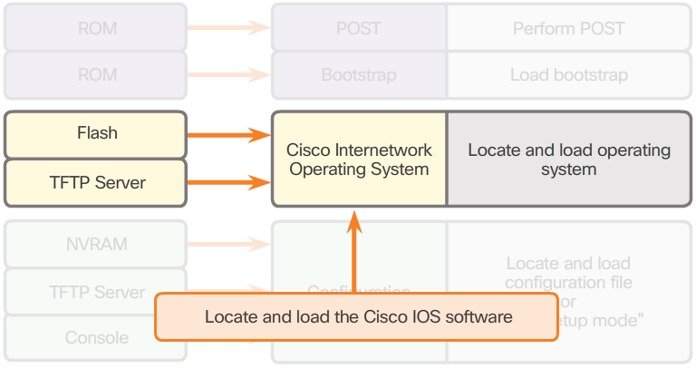
- 2. Locate and load the Cisco IOS software.
- 3. Locate and load the startup configuration file or enter setup mode.
- 1. Performing POST and Load Bootstrap Program (Figure 2)
- During the Power-On Self-Test (POST), the router executes diagnostics from ROM on several hardware components, including the CPU, RAM, and NVRAM. After the POST, the bootstrap program is copied from ROM into RAM. The main task of the bootstrap program is to locate the Cisco IOS and load it into RAM.
- Note: At this point, if you have a console connection to the router, you begin to see the output on the screen.
- 2. Locating and Loading Cisco IOS (Figure 3)
- The IOS is typically stored in flash memory and is copied into RAM for execution by the CPU. If the IOS image is not located in flash, then the router may look for it using a Trivial File Transfer Protocol (TFTP) server. If a full IOS image cannot be located, a limited IOS is copied into RAM, which can be used to diagnose problems and transfer a full IOS into Flash memory.
X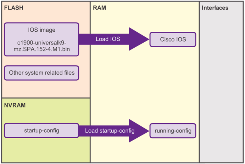 X
X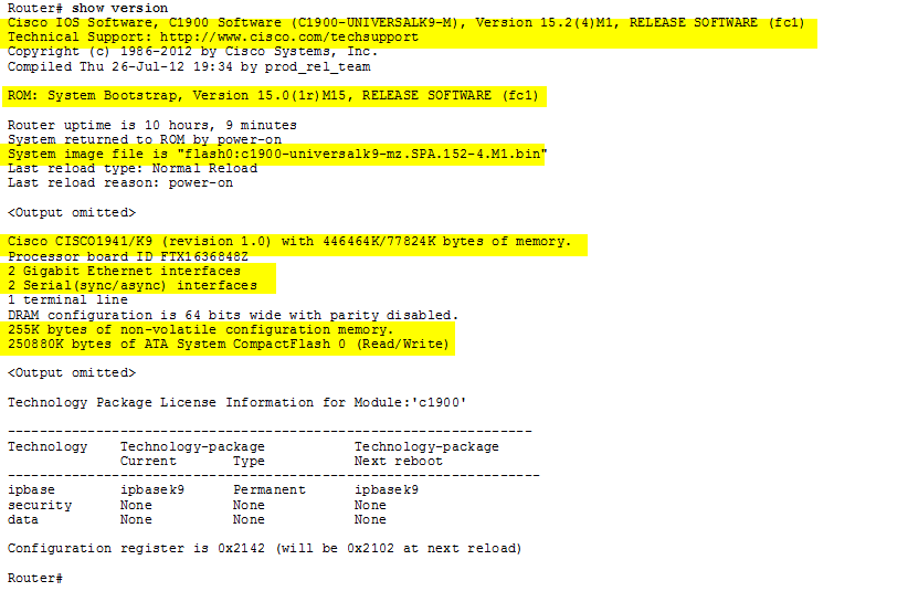
-

Verify Interface Configuration
- There are several commands that can be used to verify interface configuration. The most useful of these is the show ip interface brief command. The output generated displays all interfaces, their IPv4 address, and their current status. The configured and connected interfaces should display a Status of “up” and Protocol of “up”. Anything else would indicate a problem with either the configuration or the cabling.
- You can verify connectivity from the interface using the ping command. Cisco routers send five consecutive pings and measure minimal, average, and maximum round trip times. Exclamation marks verify connectivity.
- The 📷 figure displays the output of the show ip interface brief command, which reveals that the LAN interfaces and the WAN link are all activated and operational. Notice that the ping command generated five exclamation marks verifying connectivity to R2.
- Other interface verification commands include:
- show ip route - Displays the contents of the IPv4 routing table stored in RAM.
- show interfaces - Displays statistics for all interfaces on the device.
- show ip interface - Displays the IPv4 statistics for all interfaces on a router.
- Remember to save the configuration using the copy running-config startup-config command.
Basic Switch Configuration Steps
- Cisco routers and Cisco switches have many similarities. They support a similar operating system, support similar command structures and support many of the same commands. In addition, both devices have identical initial configuration steps when implemented in a network.
- Before we begin configuring a router, review the initial switch configuration tasks listed in the 📷 figure.
Configure Router Interfaces
- For routers to be reachable, the in-band router interfaces must be configured. There are many different types of interfaces available on Cisco routers. In this example, the Cisco 1941 router is equipped with:
- Two Gigabit Ethernet interfaces - GigabitEthernet 0/0 (G0/0) and GigabitEthernet 0/1 (G0/1)
- A serial WAN interface card (WIC) consisting of two interfaces - Serial 0/0/0 (S0/0/0) and Serial 0/0/1 (S0/0/1)
- Note: Click here for more information on the abbreviations and numbering of interfaces.
- Although not required, it is good practice to configure a description on each interface to help document the network information. The description text is limited to 240 characters. On production networks, a description can be helpful in troubleshooting by providing information about the type of network that the interface is connected to and if there are any other routers on that network. If the interface connects to an ISP or service carrier, it is helpful to enter the third party connection and contact information.
- Using the no shutdown command activates the interface and is similar to powering on the interface. The interface must also be connected to another device (a hub, a switch, or another router) for the physical layer to be active.
- The 📷 figure shows the configuration of the LAN interfaces connected to R1.
X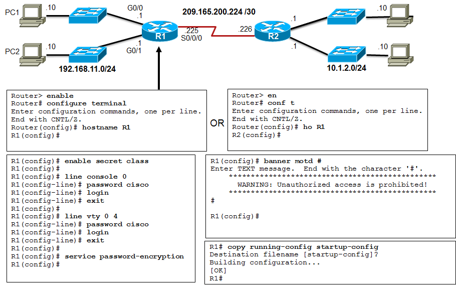 X
X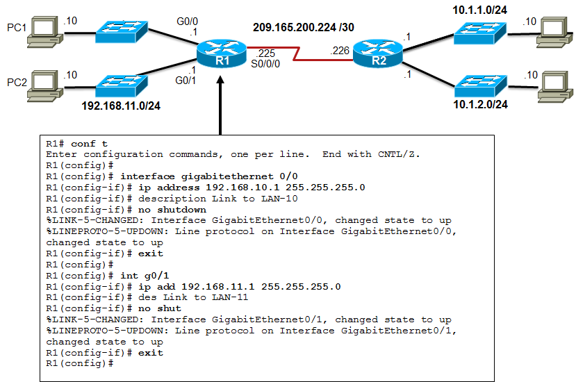 X
X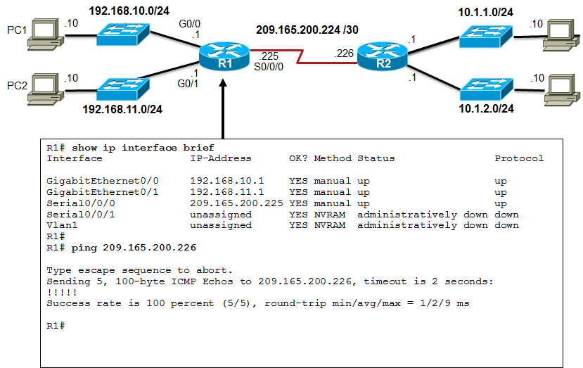
-
Default Gateway for a Host
Default Gateway for a Switch
- Typically a workgroup switch that interconnects client computers is a Layer 2 device. As such, a Layer 2 switch does not require an IP address to function properly. However, if you wish to connect to the switch and administratively manage it over multiple networks, you will need to configure the SVI with an IPv4 address, subnet mask, and default gateway address.
- The default gateway address is typically configured on all devices that wish to communicate beyond just their local network. In other words, to remotely access the switch from another network using SSH or Telnet, the switch must have an SVI with an IPv4 address, subnet mask, and default gateway address configured. If the switch is accessed from a host within the local network, then the default gateway IPv4 address is not required.
- To configure a default gateway on a switch use the ip default-gateway global configuration command. The IP address configured is that of the router interface of the connected switch.
- The 📷 figure shows an administrator connecting to a switch on a remote network. For the switch to forward response packets to the administrator, the default gateway must be configured.
- A common misconception is that the switch uses its configured default gateway address to determine where to forward packets originating from hosts connected to the switch and destined for hosts on remote networks. Actually, the IP address and default gateway information is only used for packets that originate from the switch. Packets originating from host computers connected to the switch must already have the default gateway address configured on their host computer operating systems.
- For an end device to communicate over the network, it must be configured with the correct IP address information, including the default gateway address. The default gateway is only used when the host wants to send a packet to a device on another network. The default gateway address is generally the router interface address attached to the local network of the host. The IP address of the host device and the router interface address must be in the same network.
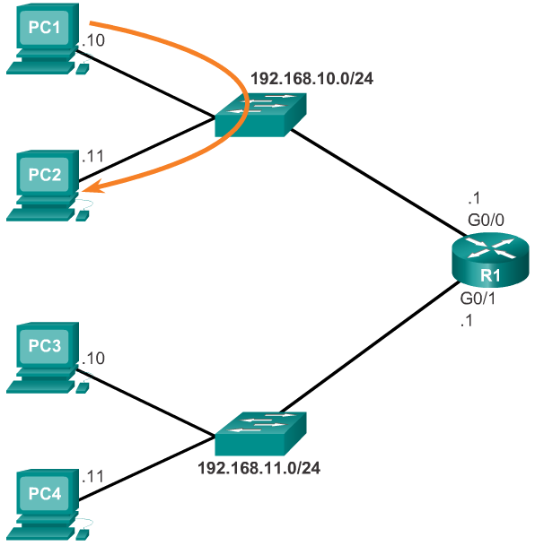
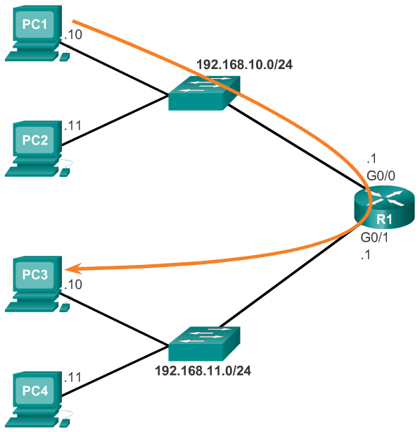
- The figures display a topology of a router with two separate interfaces. Each interface is connected to a separate network. G0/0 is connected to network 192.168.10.0, while G0/1 is connected to network 192.168.11.0. Each host device is configured with the appropriate default gateway address.
- In Figure 1, PC1 sends a packet to PC2. In this example, the default gateway is not used; rather, PC1 addresses the packet with the IP address of PC2 and forwards the packet directly to PC2 through the switch.
- In Figure 2, PC1 sends a packet to PC3. In this example, PC1 addresses the packet with the IP address of PC3, but then forwards the packet to the router. The router accepts the packet, accesses its routing table to determine the appropriate exit interface based on the destination address, and then forwards the packet out of the appropriate interface to reach PC3.
X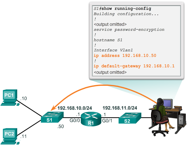
-
Summary
- In this chapter, you learned:
- The network layer, or OSI Layer 3, provides services to allow end devices to exchange data across the network.
- The network layer uses four basic processes: IP addressing for end devices, encapsulation, routing, and de-encapsulation.
- The Internet is largely based on IPv4, which is still the most widely-used network layer protocol.
- An IPv4 packet contains the IP header and the payload.
- The IPv6 simplified header offers several advantages over IPv4, including better routing efficiency, simplified extension headers, and capability for per-flow processing.
- In addition to hierarchical addressing, the network layer is also responsible for routing.
- Hosts require a local routing table to ensure that packets are directed to the correct destination network.
- The local default route is the route to the default gateway.
- The default gateway is the IP address of a router interface connected to the local network.
- When a router, such as the default gateway, receives a packet, it examines the destination IP address to determine the destination network.
- The routing table of a router stores information about directly-connected routes and remote routes to IP networks. If the router has an entry in its routing table for the destination network, the router forwards the packet. If no routing entry exists, the router may forward the packet to its own default route, if one is configured or it will drop the packet.
- Routing table entries can be configured manually on each router to provide static routing or the routers may communicate route information dynamically between each other using a routing protocol.
- For routers to be reachable, the router interface must be configured.