02
-
Measurement of Voltages and Currents
- Introduction
- Sine waves
- Square waves
- Measuring Voltages and Currents
- Analogue Ammeters and Voltmeters the following lectures will assume a basic understanding of these topics
- Digital Multimeters
- Oscilloscopes
-
Introduction
- Alternating currents and voltages vary with time and periodically change their direction
-
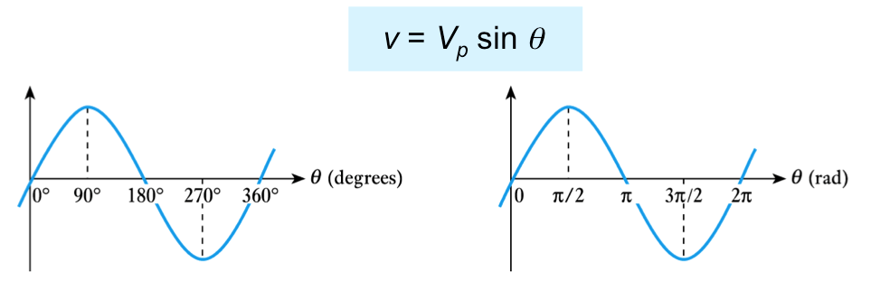
Instantaneous Value
- shape of the sine wave is defined by the sine functiony = A sin θ
- in a voltage waveform
Angular Frequency
- frequency f (in hertz) is a measure of the number of cycles per second
- each cycle consists of 2π radians
- therefore there will be 2πf radians per second
- this is the angular frequency ω (units are rad/s). ω = 2πf
Equation of a Sine Wave
- The angular frequency ω can be thought of as the rate
- at which the angle of the sine wave changes at any time. - θ=ωt
- therefore - v=Vp sin ωt or v=Vp sin 2πft
- similarly - i=Ip sin ωt or i=Ip sin 2πft
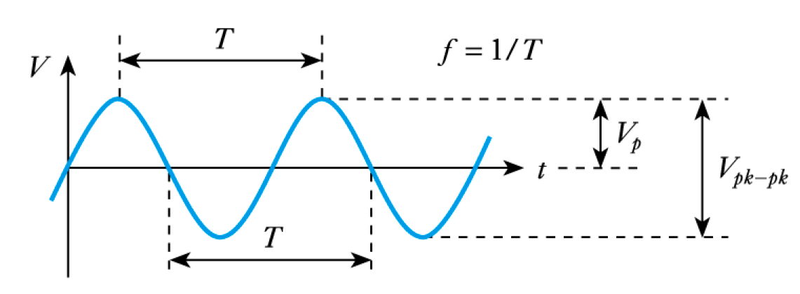
Sine Waves
- Sine Waves - by far the most important form of alternating quantity
- important properties are shown in this diagram
- 📷 A Sine Wave
- 🎥 Watch Video
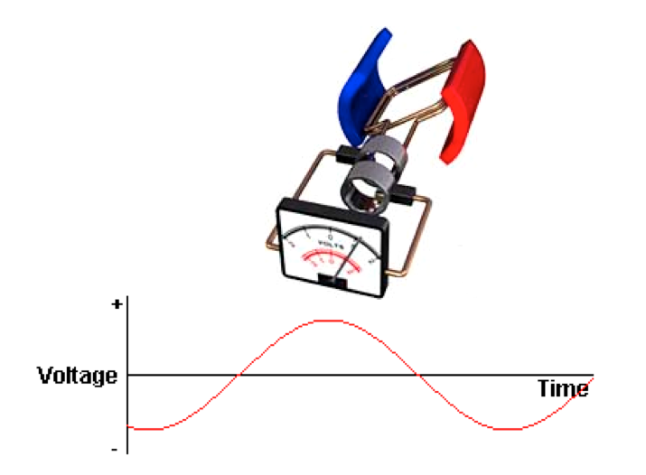
Alternating Voltages and Currents
- Alternating current (a.c.) is easier, more convenient and cheaper to
- generate than direct current (d.c.).
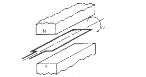
- 📷 Figure 1 is an example of a.c. generation. An emf (voltage) is
- generated in the coil which varies in magnitude and reverses in polarity
- at regular intervals
A.C. Generator
- An AC Generator
- A Sine Wave
- Alternating Current - Figure 1

-
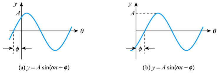
Phase angles
- The expressions given above assume the angle of the sine wave is zero at t = 0
- If this is not the case the expression is modified by adding the angle at t = 0
Phase difference
- Two waveforms of the same frequency may have a constant
- phase difference.
- We say that one is phase-shifted with respect to the other
Example
- - see Example 2.2 in the course text.
- Determine the equation of the following voltage signal.
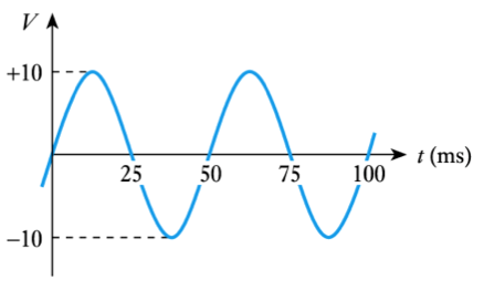
- From the diagram:
- Period is 50ms = 0.05 s
- Thus f = 1/T =1/0.05 = 20 Hz
- Peak voltage is 10 V
- Therefore, v=Vp sin 2πft = 10sin 2π20t = 10sin 126t


-
r.m.s. value of a sine wave
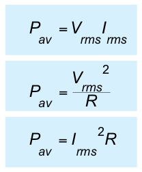
- the instantaneous power (p) in a resistor is given by

- therefore the average power is given by
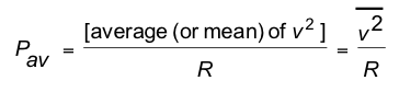
- where
 is the mean-square voltage
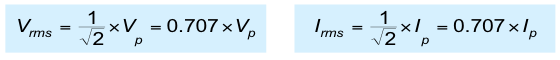
- While the mean-square voltage is useful, more often we use the square root of this quantity, namely the root-mean-square voltage Vrms
- where Vrms =

- We can also define Irms =

- it is relatively easy to show that (see text for analysis)
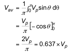
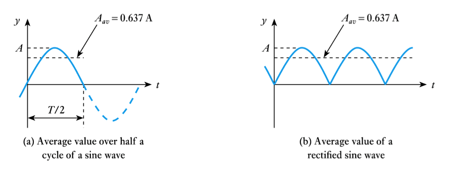
Average value of a sine wave
- Average value over one (or more) cycles is clearly zero.
- However, it is often useful to know the average magnitude of the waveform independent of its polarity
- we can think of this as the average value over half a cycle…
- … or as the average value of the rectified signal
-
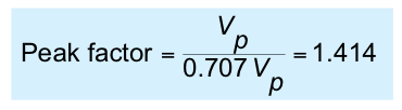
Peak factor
- for any waveform the peak factor is defined as
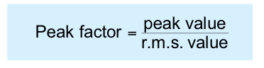
- for a sine wave this gives
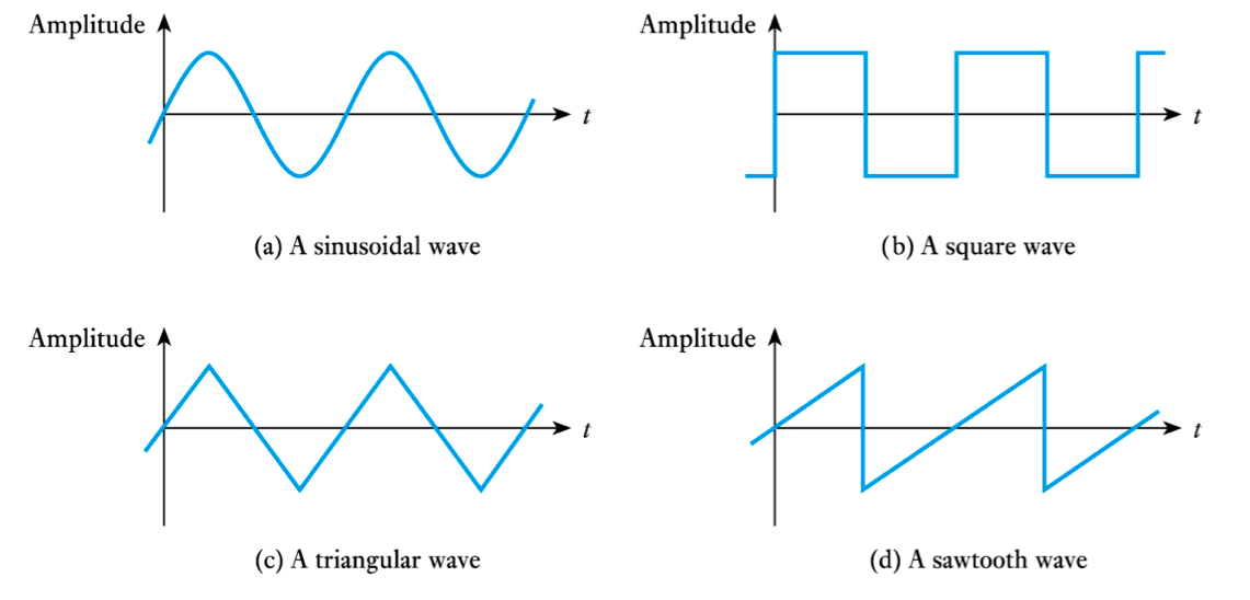
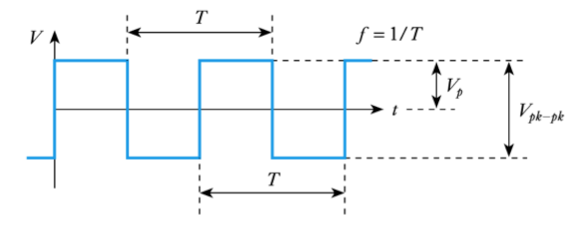
Square Waves
- Frequency, period, peak value and peak-to-peak value have the same meaning for all repetitive waveforms
r.m.s. value of a sine wave (cont.d)
- r.m.s. values are useful because their relationship to average power is similar to the corresponding DC values
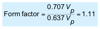
Form factor
- for any waveform the form factor is defined as
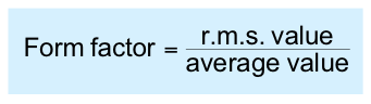
- for a sine wave this gives
-
Average and r.m.s. values
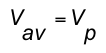
- the average value of a symmetrical waveform is its average value over the positive half-cycle
- thus the average value of a symmetrical square wave is equal to its peak value
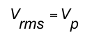
- similarly, since the instantaneous value of a square wave is either its peak positive or peak negative value, the square of this is the peak value squared, and
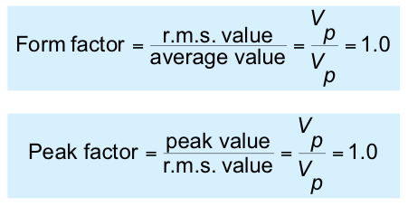
Form factor and peak factor
- from the earlier definitions, for a square wave
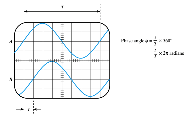
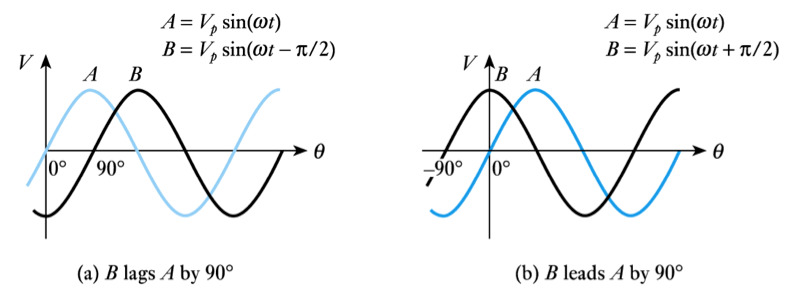
Phase angle
- we can divide the period into 360o or 2π radians
- useful in defining phase relationship between signals
- in the waveforms shown here, B lags A by 90o
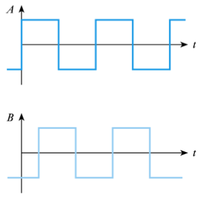
- we could alternatively give the time delay of one with respect to the other
Pause for Thought
- What kind of voltage is coming from the mains supply, d.c. or a.c.?
- What is the frequency of the mains supply?
- What is the frequency of d.c. voltage?
- What is the peak value of the mains supply?
-
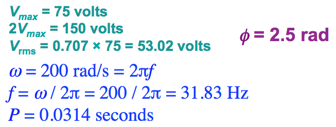
Worked Example 2

- An alternating voltage is given by v = 75 sin (200t - 2.5) volts.
- Find the amplitude Vmax, the peak to peak value (2×V max), the rms value Vrms, the periodic time P, the frequency ƒ and the relative phase angle Φ
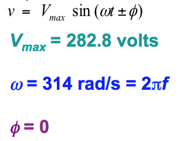
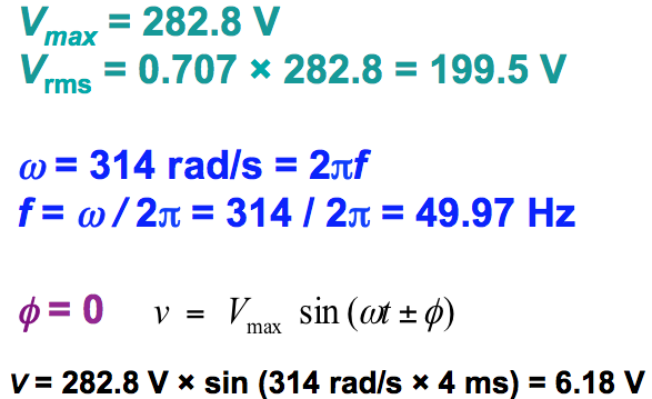
Worked Example 1
- An alternating voltage is given by v = 282.8 sin 314t volts. Find the rms voltage, the frequency and the instantaneous value when t = 4 ms.
-
Measuring Voltages and Currents
- 🎥 Watch Video
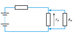
Loading effects – voltage measurement
- our measuring instrument will have an effective resistance (RM)
- when measuring voltage we connect a resistance in parallel with the component concerned which changes the resistance in the circuit and therefore changes the voltage we are trying to measure
- this effect is known as loading
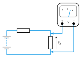
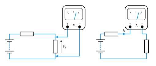
Measuring voltage and current in a circuit
- when measuring voltage we connect across the component
- when measuring current we connect in series with the component
-
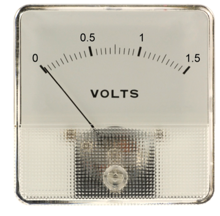
Analogue Ammeters and Voltmeters
- Most modern analogue ammeters are based on moving-coil meters
- see Chapter 13 of textbook
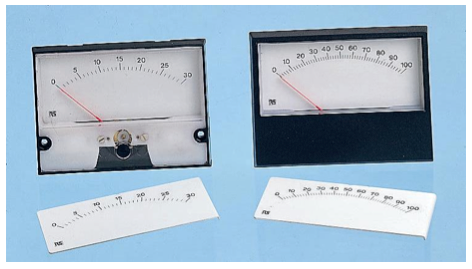
- Meters are characterised by their full-scale deflection (f.s.d.) and their effective resistance (RM)
- typical meters produce a f.s.d. for a current of 50 μA – 1 mA
- typical meters have an RM between a few ohms and a few kilohms
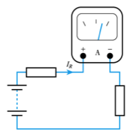
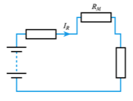
Loading effects – current measurement
- our measuring instrument will have an effective resistance (RM)
- when measuring current we connect a resistance in series with the component concerned which again changes the resistance in the circuit and therefore changes the current we are trying to measure
- this is again a loading effect
-
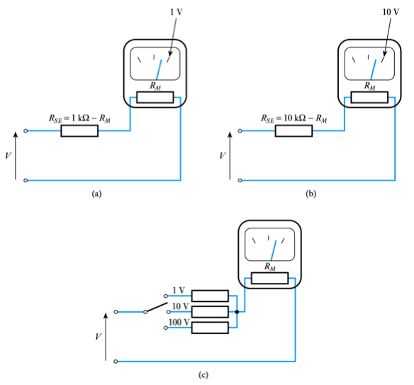
- Measuring direct voltages using a moving coil meter
- use a series resistor to adjust sensitivity
- see Example 2.6 in the set text for numerical calculations
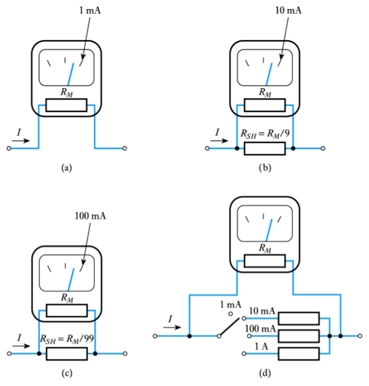
- Measuring direct currents using a moving coil meter
- use a shunt resistor to adjust sensitivity
- see Example 2.5 in the set text for numerical calculations
-
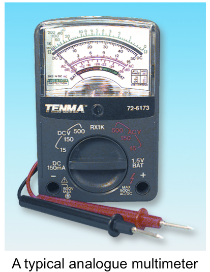
Analogue multimeters
- General purpose instruments use a combination of switches and resistors to give a number of voltage and current ranges.
- - a rectifier allows the measurement of AC voltage and currents
- - additional circuitry permits resistance measurement
- - very versatile but relatively low input resistance on voltage ranges produces considerable loading in some situations
Measuring alternating quantities
- Moving coil meters respond to both positive and negative voltages, each producing deflections in opposite directions.
- - a symmetrical alternating waveform will produce zero deflection (the mean value of the waveform).
- - therefore we use a rectifier to produce a unidirectional signal.
- - meter then displays the average value of the waveform.
- - meters are often calibrated to directly display r.m.s. of sine waves.
- all readings are multiplied by 1.11 – the form factor for a sine wave
- - as a result waveforms of other forms will give incorrect readings.
- for example when measuring a square wave (for which the form factor is 1.0, the meter will read 11% too high)
-
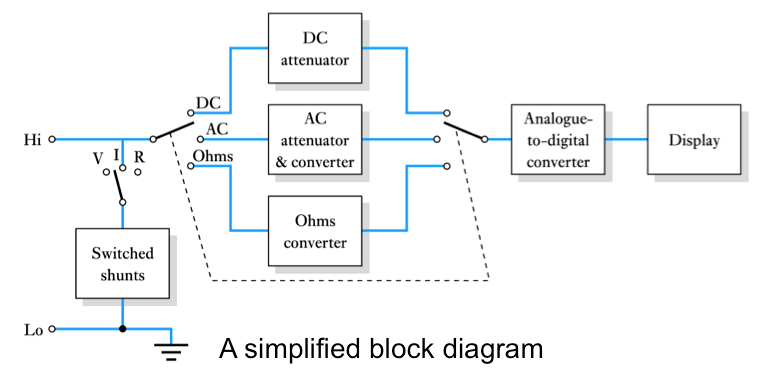
- Measurement of voltage, current and resistance is achieved using appropriate circuits to produce a voltage proportional to the quantity to be measured .
- in simple DMMs alternating signals are rectified as in analogue multimeters to give its average value which is multiplied by 1.11 to directly display the r.m.s. value of sine waves
- more sophisticated devices use a true r.m.s. converter which accurately produced a voltage proportional to the r.m.s. value of an input waveform
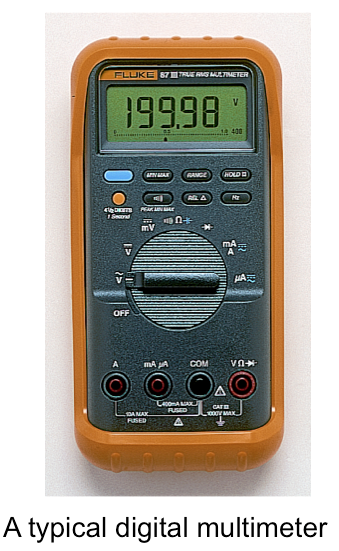
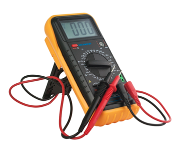
Digital Multimeters
- Digital multimeters (DMMs) are often (inaccurately) referred to as digital voltmeters or DVMs.
- at their heart is an analogue-to-digital converter (ADC) .
- - therefore we use a rectifier to produce a unidirectional signal.
-
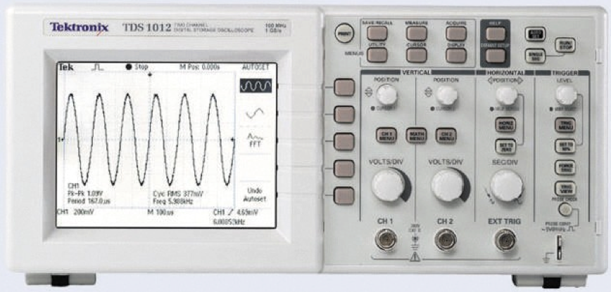
Digital oscilloscope
- Digital oscilloscopes use an analogue-to-digital converter (ADC) and appropriate processing.
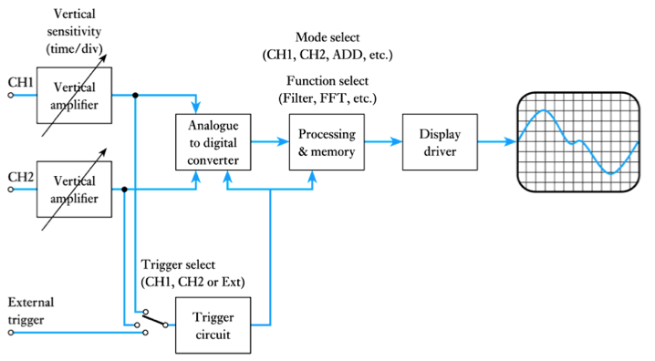
- A typical digital oscilloscope
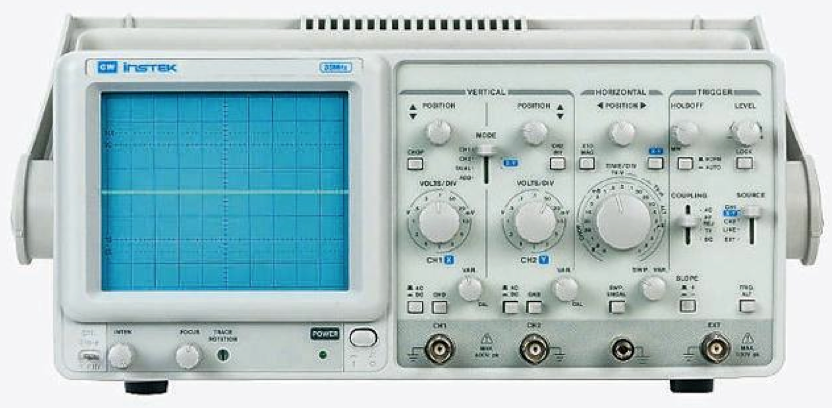
Oscilloscopes
- An oscilloscope displays voltage waveforms
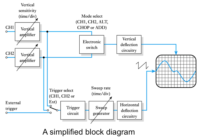
- A typical analogue oscilloscope
-
Further Study
- The Further Study section at the end of Chapter 2 looks at the measurement of different forms of alternating waveform.
- Have a look at the problem and then watch the video to see how you did.
🎥 Watch Video
Key Points
- The magnitude of an alternating waveform can be described by its peak, peak-to-peak, average or r.m.s. value
- The root-mean-square value of a waveform is the value that will produce the same power as an equivalent direct quantity
- Simple analogue ammeter and voltmeters are based on moving coil meters
- Digital multimeters are easy to use and offer high accuracy
- Oscilloscopes display the waveform of a signal and allow quantities such as phase to be measured.
- Measurement of phase difference