07
-
Learning Outcomes
- Ability to use common drawing tools to construct engineering drawings.
- Apply dimensions on engineering drawings.
- Read, understand and construct engineering drawings.
- Justify the need for different views.
- Build 1st and 3rd angle orthographic projections using three view drawings.
- Create 2D drawings.
- Use standards scales and units to produce engineering drawings.
- Produce simple assembly drawings.
- Use this link to view the Lecture Video for Section 7 📹
Sketching, Engineering Drawing Conventions and 1st Angle Orthographic Projection
- Engineering drawings are geometric representations of an idea or product which are used to define, establish and create products development to production. Upon completion of Engineering Drawings sections you will be able to develop familiarity with and identify technical drawing types.
Please stop the video before closing the light box !
-
Layout Drawings
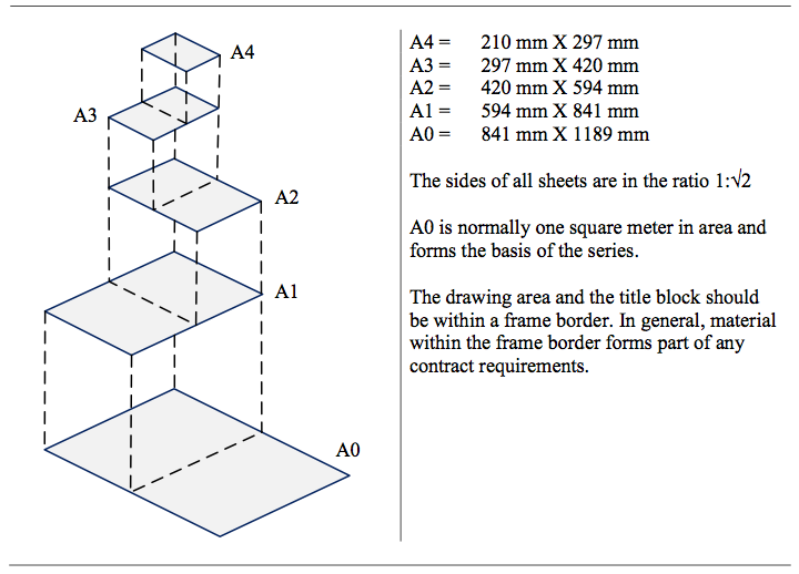
- Drafting media come in standard sheet sizes. Table 14.1 compares ‘A’ series of International Standards Organization (ISO) drawing sizes.
- Table 14.1: Comparison of drawing format sizes with ISO paper sizes
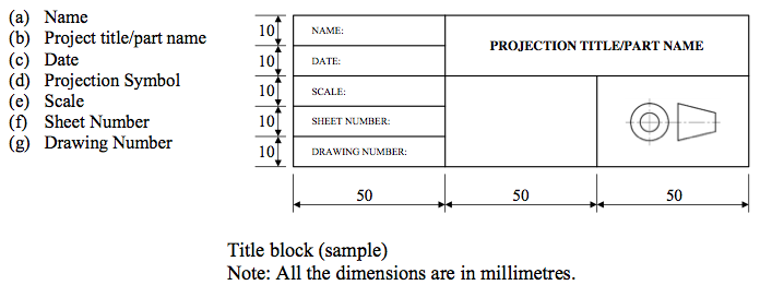
Title Blocks
- The title block is a very important part of an engineering drawing which locates in the lower right corner of the format. The title block should include spaces for the following basic information.
Types of Drawings
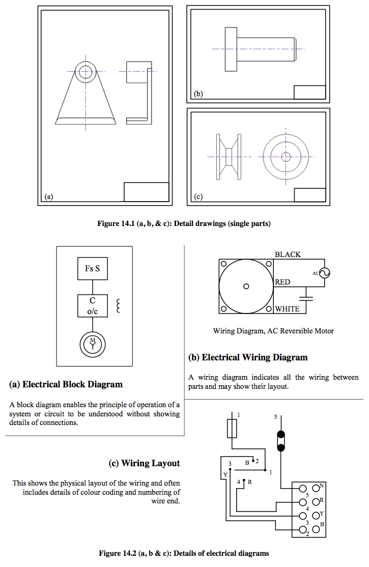
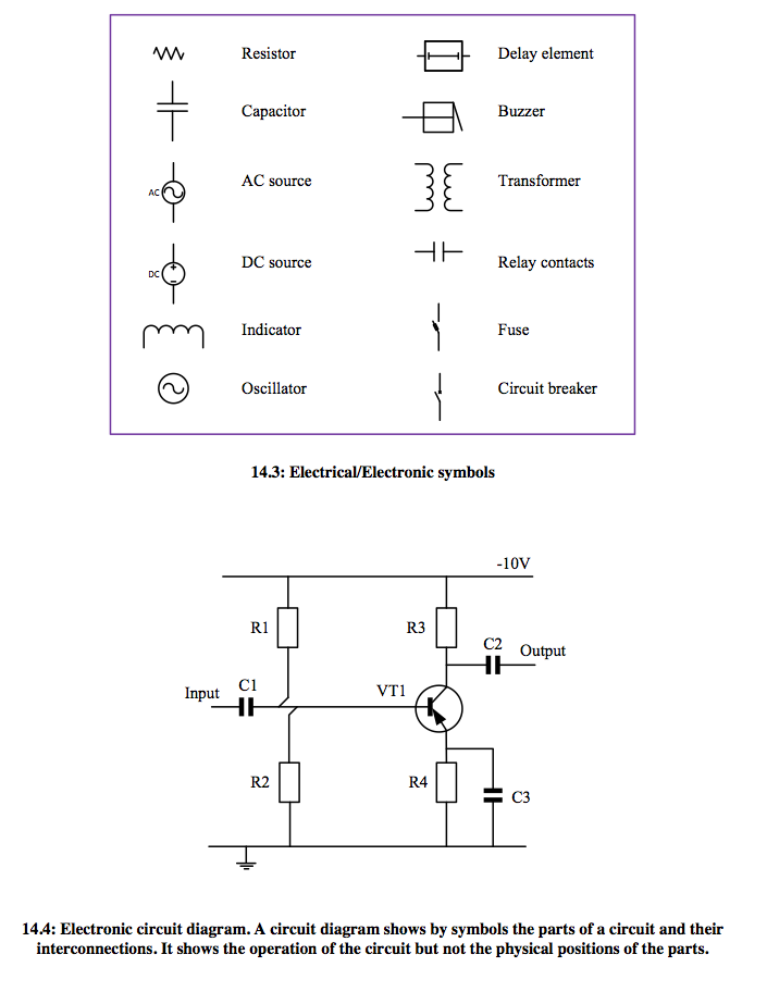
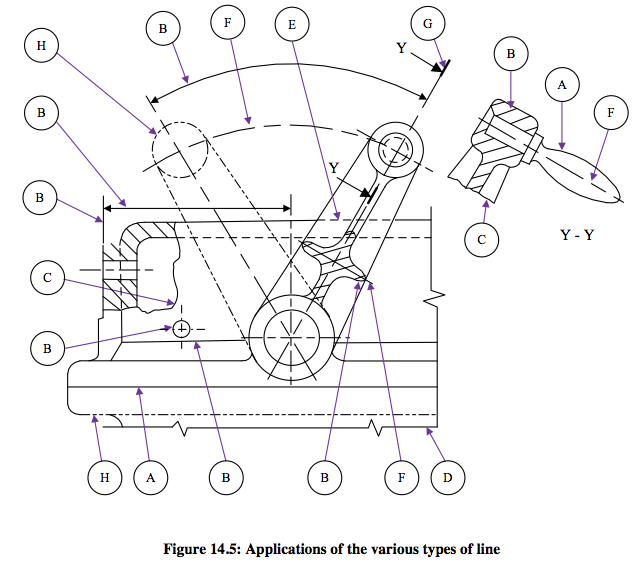
- There are different types of drawings used in engineering; mechanical (Figure 14.1a, 14.1b & 14.1c), electrical (Figure 14.2a, 14.2b & 14.2c) and electronic (Figure 14.4).
Drawing Formats
- Drawing sheets have two formats.
- Portrait: intended to be viewed with the longest side of the sheet vertical (Figure 14.1a).

- Landscape: intended to be viewed with the longest side of the sheet horizontal (Figure 14.1 (b & C)).

-
Scales
General- Every drawing should be drawn in proportion, i.e. to a uniform scale. The scale used should be started on the drawing as a ratio, e.g. ORIGINAL SCALE 1:2. The words full size, half size, etc., should not be used.
Recommended Scales- These are as follows:
- Full Size
- 1:1
- On drawings smaller than full size (reduction scales)
1:2 1:5 1:10 1:20 1:50 1:100 1:200 1:500 1:1000
- On drawings larger than full size (enlargement scales)
2:! 5:1 10:1 20:1 50:! 100:1
Choice of Scales- The scale to be chosen for a drawing depends on the size of the drawing sheet and the size of the object to be depicted. The scale should be large enough to permit easy and clear interpretation of the information. Details those are too small for clear dimensioning in the main representation should be shown in a separate view to a larger scale.
-
Lines and Linework
Presentation- All lines should be uniformly black, dense and bold. Lines should be all in pencil or all in black ink.
Line Thickness- Two thicknesses of line are recommended: thick and thin. Thick lines should be twice as thick (wide) as thin lines.
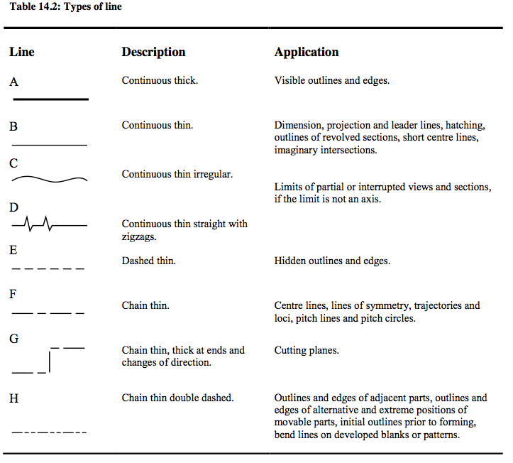
Types of Lines and Their Applications- See Table 14.2 and Figure 14.5.
- Dashed lines (type E). The dashes should be of consistent length and spacing, approximately to the proportion shown in Table 14.2. Dashed lines should start and end with dashes in contact with the hidden or visible lines from which they originate, except when the hidden line continues a visible line. Dashed lines should also meet with dashes at tangent points and corners.
- Chain lines (type F, G and H). All chain lines should start and finish with a long dash, but note the length of the thick dash at the ends of the cutting plane line (type G) and at the changes of direction.
- Where centre lines define centre points they should cross one another at long dash portions of the line.
- Centre lines should extend only a short distance beyond the feature or view to which they apply. If required for dimensioning they should continue as projection lines. Common centre lines should not extend across the space between adjacent views.
- Centre lines should not stop at another line of the drawing.
- Where angles are formed in chain lines, long dashes should meet or cross at corners.
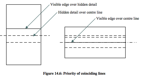
Coinciding Lines- When two or more lines of different type coincide, the following order of priority should be observed:
a) Visible outlines and edges (type A);
b) Hidden outlines and edges (type E);
c) Cutting planes (type G);
d) Centre lines, etc. (type F and B);
e) Outlines and edges of adjacent parts, etc. (type H);
f) Projection lines (type B).
- Figure 14.6 illustrates the more common priorities of coinciding lines.
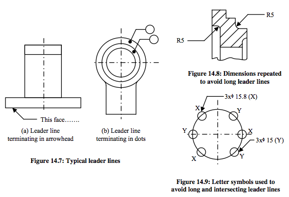
Leader Lines- Leader lines are used to show where dimensions or notes apply. They are type B lines (see table 14.2) ending in arrowheads or dots. Arrowheads always touch and stop on a line; dots should be within the outline of an object (see Figure 14.7).
- An arrowed leader line applied to an arc should be in line with the arc centre.
- When applied to a straight line an arrowed leader line should be nearly normal to the line.
- Long or intersecting leader lines should not be used even if this means repeating dimensions or notes (see Figure 14.8) or using letter symbols (see Figure 14.9).
- Leader lines should not pass through the intersection of other lines.
Arrowheads- Arrowheads should be triangular, with the length approximately three times the width, formed with straight lines and symmetrically placed about the dimension line, leader line or stem. Arrowheads should be filled in.
- Sizes. Arrowheads on dimension and leader lines should be 3 mm to 5 mm long. Arrows showing direction of viewing should have arrowheads 7 mm to 10 mm long. The stem of such arrows should be approximately the same length as the arrowhead, but not less than this.
-
Direction of Letters- Notes and captions should be placed so that they can be read in the same direction as the information in the title block.
Location of Notes- Notes of a general character should be grouped together and not spread over the drawing.
- Notes relating to specific details should appear near the relevant feature, but not so near as to crowd the view.
Underlining- Underlining of notes is not recommended. Larger characters should be used to draw attention to a note or caption.
Lettering and Numerals
General- Clarity, style, spacing and size are important. Numerals especially should be drawn clearly as they often have to be read on their own. All strokes should be black and of uniform density.
Style- In general, capital letters should be used. Some suggested examples of letters and numerals are shown in Figure 14.10.
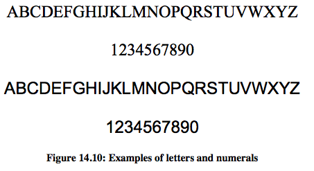
Character Height- The dimensions and notes should be not less than 3 mm tall. Titles and drawing numbers are normally larger.
-
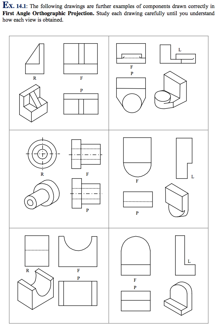
- Examples of first and third angle projection are shown in Figure 14.12 and 14.13.
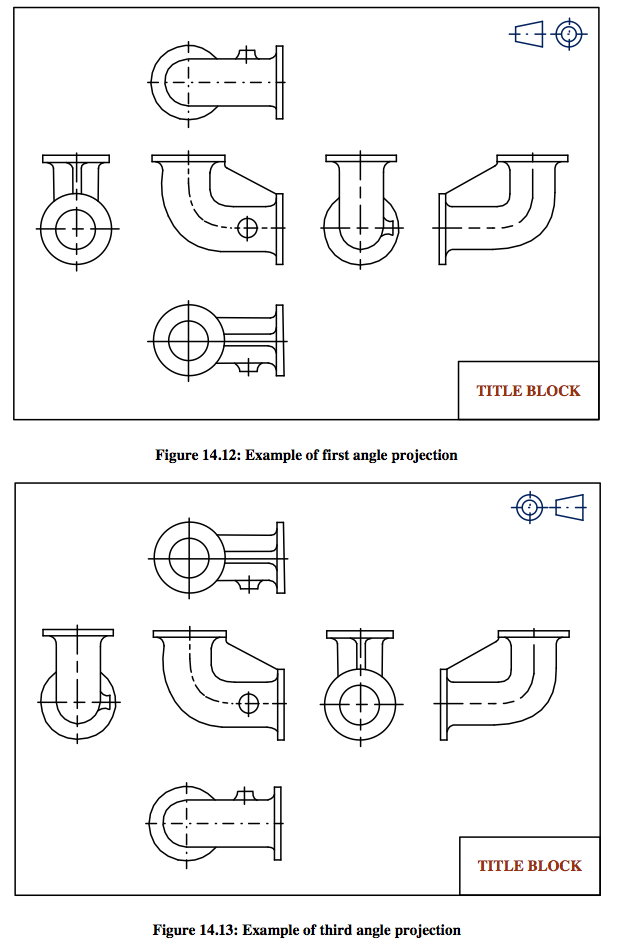
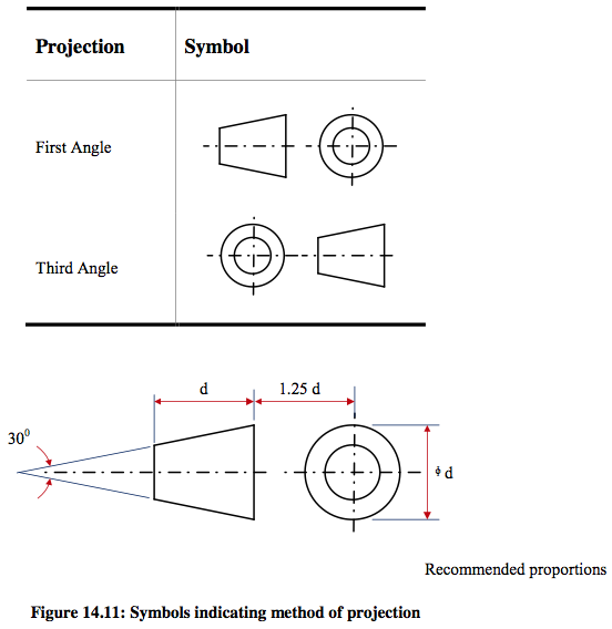
Symbol of Projection
General- Either first or third angle projection may be used. Mixed projections on one drawing are undesirable. If, exceptionally, a view cannot be conveniently shown in its correct projected position, the direction of viewing should be clearly shown. An arrow and view title may be used, similar to those in Figure 14.8.
Projection Symbols- The system of projection used on a drawing should be indicated by the appropriate symbol given in Figure 14.11.
-
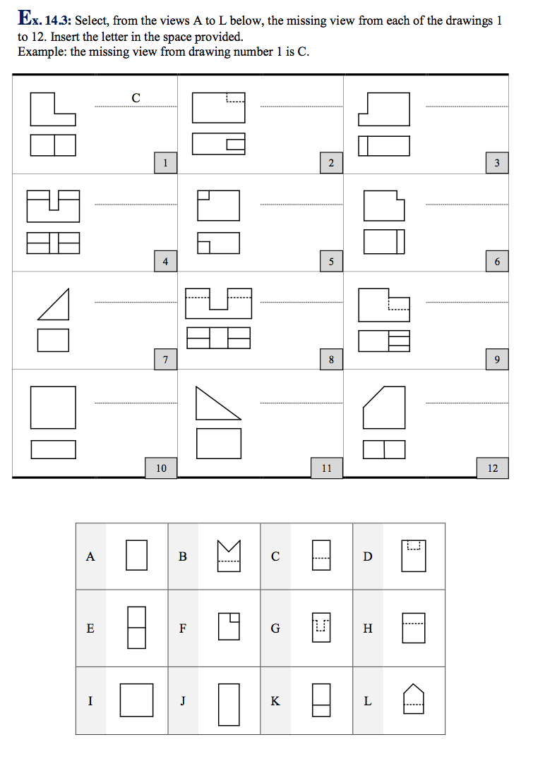
- The separate views of the component are combined to form a complete orthographic drawing as shown below (Figure 14.15). The front and side views are drawn in line with each other so that the side view may be “projected” from the front view and vice versa. The plan view is drawn in line with and below the front view. In other words, the plan is projected from the front view.
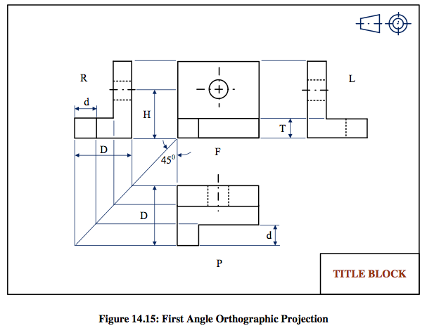
- Points to note when making a drawing using First Angle Orthographic Projection:
- 1) Corresponding heights in the front view and side view are the same. For example, the height of the hole from the base, H, is the same in both front and side views. The thickness of the base, T, is the same in both front and side views.
- 2) Widths in the side view correspond to depths in the plan. For example, the total width, D, in the side view is the same as the total depth, D, in the plan.
The width, d, is the same in both plan and side views.
Projection of widths from side view to plan is made easier by using the 450 swing line as shown.- 3) The plan view is usually projected BELOW the front view. It can be above but this would be called in “inverted” plan.
- 4) The R.H. side view is shown on the L.H. side of the front view. The L.H. side view is shown on the R.H. side of the front view.
- Note: Drawings should be read (or interpreted) by viewing from the R.H. side or bottom R.H. corner of the drawing.
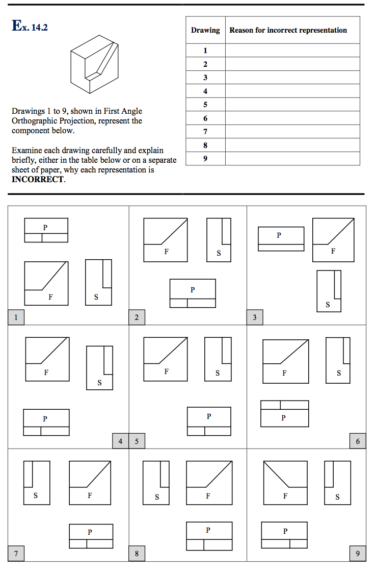
Orthographic Projection: Frist Angle
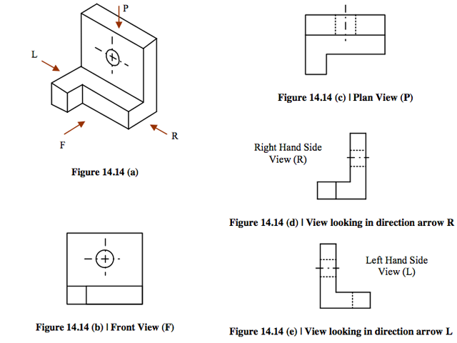
- The pictorial drawing opposite indicates the shape of the component with a single view. An orthographic drawing indicates the shape of a component by using a different face of the component.
- At least two views are necessary to fully represent the component. Usually, however, three views are shown in order to clarify internal and external derail:
- 1. A front view
2. A plan view
3. A side view
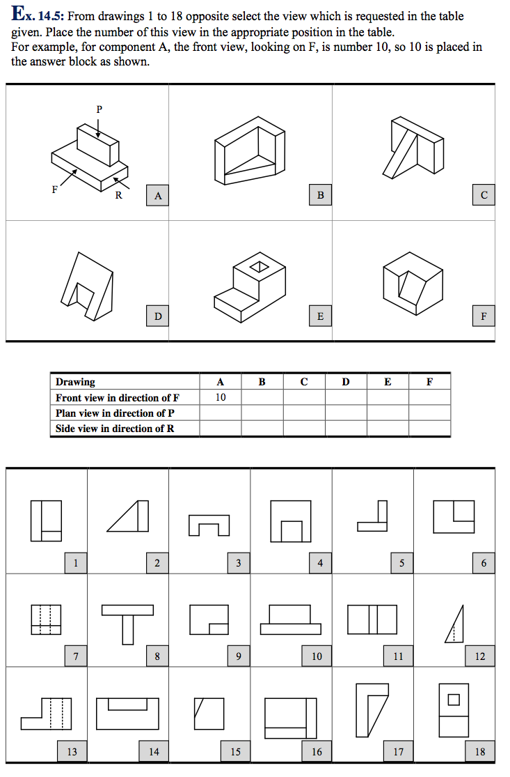
- 1. The front view, or front elevation, represents what is seen when looking at the front of the component in the direction of arrow F.
- 2. The plan view represents what is seen when looking at the top of the component in the direction of arrow P at 900 to arrow F.
- 3. A side view, or side elevation, represents what is seen when looking at the side of the component in the direction of either arrow R or arrow L. these arrows are 900 to both arrow F and arrow P.
-
-
- A number of the basic rules of dimensioning can be explained by reference to the above drawing of a thin plate. The sides marked A and B are used as reference edges which may be or may not be machined. Even if the edges are not machined it is good practice to choose reference edges in order to simplify the layout of the dimensions.
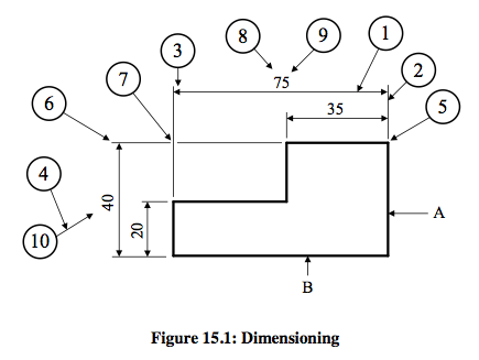
- Points to note:
1. DIMENSION LINES – thin full lines placed outside the component where possible and spaced well away from the outlines. The longer dimension lines are placed outside shorter ones.
2. EXTENSION LINES – thin full lines which extend from the view to provide a boundary for the dimension line. Drawn at 900 to the outline.
3. ARROWHEADS – drawn with sharp strokes which must touch the extension lines.
4. A LEDER LINES – thin full lines which are drawn from a note, a dimension or, in this case, a balloon and terminates in an arrowhead or a dot.
5. Relatively small gap.
6. Relatively short tail.
7. Crossing extension lines usually a break to ensure clarity.
8. Dimension placed above the dimension line. This is preferred to the alternative method of placing the dimension in a gap in the line. Avoid using both methods on the same drawing if possible.
9. Dimension placed so that it may be read from the bottom or
10. Dimension placed so that it may be read from the right hand side of the drawing sheet.
11. Study this information before turning to the next page.Dimensioning of Engineering Drawings
- Any drawing from which a component is to be made must convey information from the designer to the craftsmen in three ways. It must;
● Describe the shape of the component by using orthographic and, sometimes pictorial views.
● Give sizes by dimensioning.
● Provide information about the workshop processes involved.
Draughtsmen and designers should understand not only methods of projection, but also dimensioning methods and processes required for the manufacture of an engineering component, so that correct instructions may be issued to the craftsman. Most of the problems of dimensioning may be solved by the application of a few simple rules. Some may be simply stated, e.q. 1, 2 and 3 below whilst others can be more easily explained by reference to diagrams.
1. Dimensions should be placed on drawings so that they may be easily read. They must be clearly printed and placed outside the outline of the most appropriate view where possible.
2. The drawing must include the minimum number of dimensions necessary to manufacture the component and a dimension should not be stated more than once unless it aids communication.
3. It should not be necessary for dimensions to be deduced by the craftsman.
The way a draughtsman dimensions a component or assembly is influenced also by the need to consider the type of dimension he will use.
These may be classed broadly as;
I. SIZE DIMENSIONS – used to describe heights, widths, thicknesses, diameters, radii, etc., and, where appropriate, the shapes of the component.
II. LOCATION DIMENSIONS – necessary to locate the various features of a component relative to each other, to a reference surface or to a centre line, etc.
III. MATING DIMENSIONS – applied to parts that fit together. This implies a certain degree of accuracy, and in the case of shafts which fit into holes, the application of limits and fits will most likely be necessary.
All the examples in this section are intended to explain the rules of dimensioning which are set out as recommendations in BS 308: Part 2: 1972. It must be stressed, however, that the dimensioning of any component depends on the draughtsman’s interpretation of the recommendations. A component may be dimensioned in a number of different ways yet still be dimensioned correctly. -
- The figures shown below are dimensioned incorrectly.
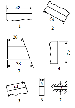
- Exercise: Dimension the figures correctly.
Arrangement of Dimensions
- Dimensions should be placed so that they may be read from either the bottom or right-hand side of the drawing.
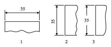
- The arrangements at 1 and 2 are the most usual but there are occasions when it may be necessary to use the arrangement at 3.
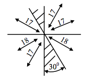
- Avoid placing dimension lines in the shaded area – zones of about 300.
- Various methods of dimensioning narrow spaces or widths are shown below. Note the placing of the arrows outside the extension lines.
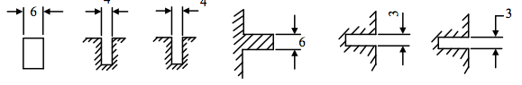
-
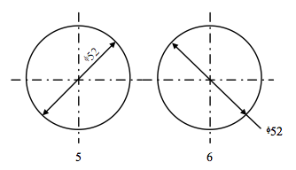
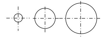
And larger circles
- When the dimension line has to be drawn as in example 6 it is preferable to place the dimension as shown so that it may be easily read from the bottom of the sheet.
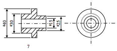
For diameters of cylinders- In this example it is preferable to dimension the side view even through the cylindrical shape is not apparent. Dimensions in this view, however, must always be preceded by the symbol ɸ.
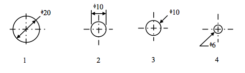
Dimensioning Circles
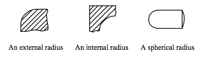
- On an engineering drawing a circle may be one of the following.
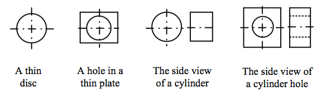
- The way a circle is dimensioned is influenced by the factors shown above and also by the size of the circle and the space available within the circle.
- Points to note:
• The dimension always refers to the diameter and NOT the radius.
• A circle is never dimensioned on a centre line.
• The conventional symbol for diameter is ɸ.
- Methods used for dimensioning relatively small circles.
-
- The circles shown below are incorrectly dimensioned.
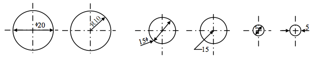
- Exercise: Dimension the circles on the right correctly using the information given on the previous page.
- The radii below are dimensioned incorrectly.
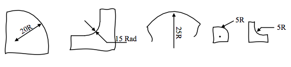
- Exercise: Dimension the radii below correctly using the information given on the previous page.
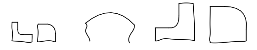
Dimensioning Radii
- n an engineering drawing a radius usually describes the shape or contour of a component in a particular view and may be either;
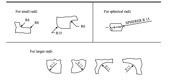
- A radius should be dimensioned by a dimension line which passes through, or is in line with, the centre of the arc. The dimension line should have one arrowhead which should be placed at the point of contact with the arc. The abbreviation R should always precede the dimension.
- The above statements may be interpreted as follows:
-
Exercise 1
- For the safety key shown below, draw to a scale of 1:1 in First Angle Projection, an END ELEVATION on arrow B, a PLAN on arrow A and an ELEVATION on arrow C showing all dimensions necessary for manufacturing.
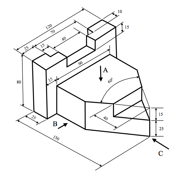
- Note: use A3 paper and clearly mention the details of the title block.
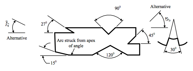
Dimensioning Angles
- Angles should be expressed in:
Degrees e.g. 900, 450
Degrees and minutes e.g. 270 30’, 450 30’.
- Angles may be dimensioned using one of the methods shown in these examples.
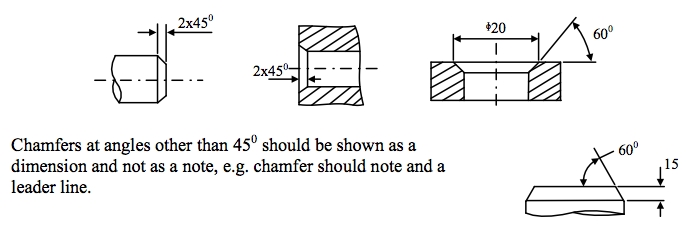
Dimensioning chamfers
- 45o chamfers should be specified by one of the methods shown below: