08
-
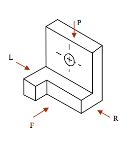
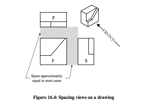
- In Third Angle Orthographic Projection the individual views are placed on the drawing sheet in projection with each other as shown:
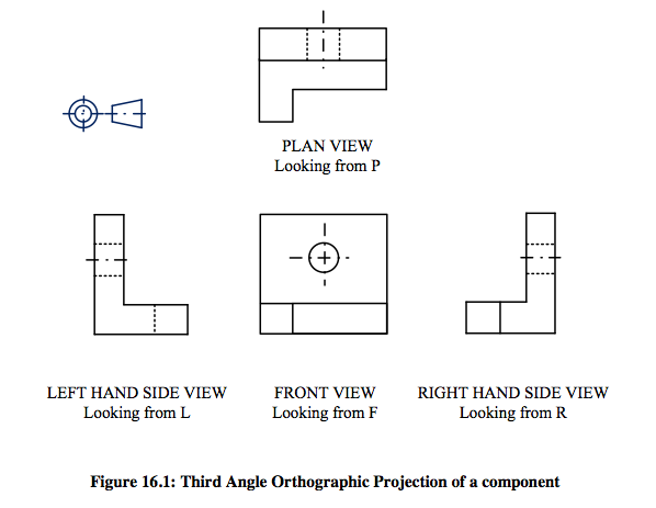
- Special points to note:
• The PLAN is always projected ABOVE the FRONT view.
• The RIGHT HAND SIDE view is shown on the RIGHT HAND SIDE of the FRONT view.
• The LEFT HAND SIDE view is shown on the LEFT HAND SIDE of the FRONT view.:3rd Angle Orthographic Projection
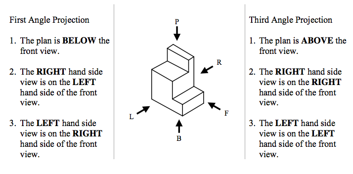
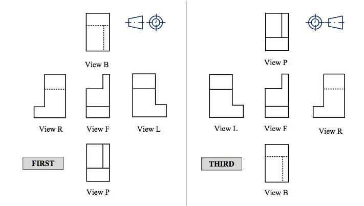
- You may remember from information presented earlier in the text that there are two methods of orthographic projection used in the preparation of engineering drawings. You should, by now be quite conversant with one of them – First Angle Orthographic Projection. The other is known as Third Angle Orthographic Projection. When representing a three dimensional component in Third Angle Orthographic Projection, the basic views are exactly the same as those shown when using First Angle Orthographic Projection. The difference between First Angle and Third Angle is in the positioning of the views relative to each other.
-
A Comparison of First Angle Projection and Third Angle Projection
-
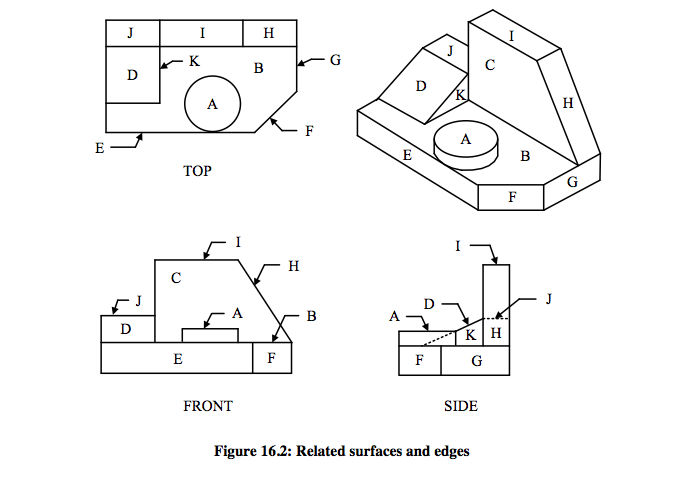
- Surface B. True shape in the top view.
- Shows as an edge in the front and side views of the drawing.
- Surface C. True shape in the front view.
- Shows as an edge view in the top and side views.
- Surface D. An angled surface.
- The front and top projections are not true shape.
- Surface E. True shape in the front view.
- Shows an edge in the top and side views.
- Surface F. An angled surface.
- Does not show in any view as true shape.
- Surface G. Shows an edge in the top view.
- True shape in the side view.
- Surface H. Shows as an edge in the front view.
- Shows fore-shortened in the other two views.
- Surface I. True shape in the top view.
- Shows as an edge in the front view and fore-shortened in the side view.
- Surface J. True shape in the top view.
- Edges in the other two projections.
- Surface K. True shape in the side view.
- hows as an edge in the front and top views.
Visualising Areas on Adjacent and Related Views
- Visualisation is important to examine an element by comparing edges and surfaces on adjacent and related views. As illustrated in Figure 16.2, a good example for studying shapes and surfaces, the true shape (surface A) in the top view shown as an edge in the front and side projections. Further, related area on adjacent and related views of drawing are summarised as below;
-
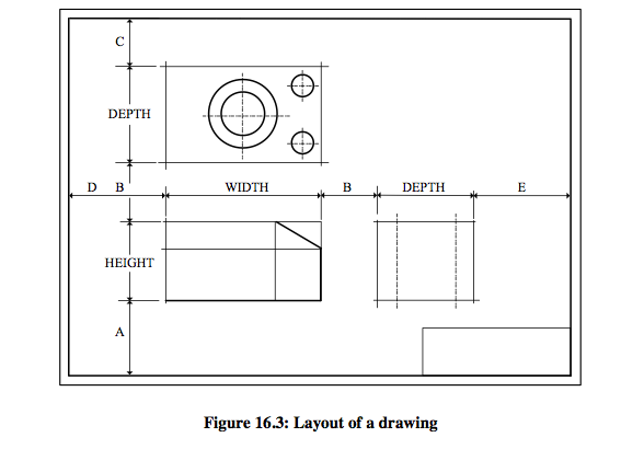
Spacing Views
- After deciding the number of views to be established, the next step is to select the paper size and determine the space for views, dimensions and notes. There are no hard and fast rules for drawing layouts. In general, all the views must place in the centre of the drawing sheet with allowable spaces between views and the margins as illustrated in Figure 16.3. The paper size, and dimensions A, B, C, D and E should definite depending on the scale and dimensions of the part to be drawn.
-
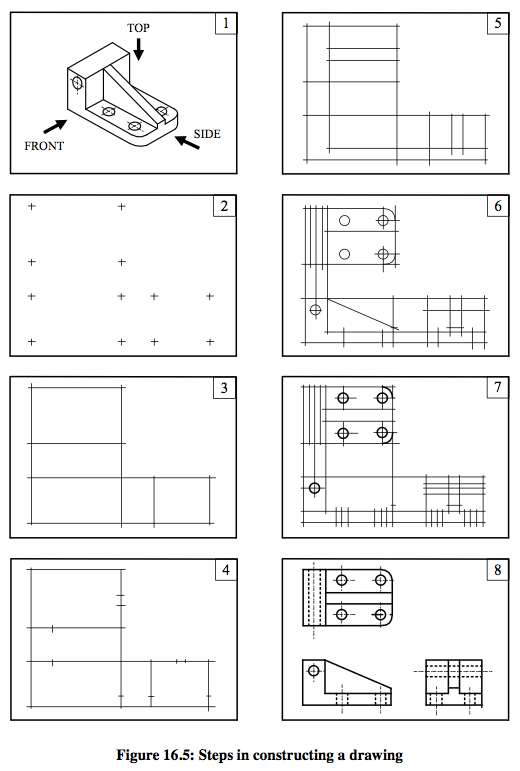
Steps in Constructing a Drawing
- Figure 16.5 illustrates steps in the constructing a drawing.
- An isometric view of the part to be drawn is shown in Figure 16.5 (1). To establish a well- planned drawing determine the sheet size, scale, dimensioning and possible view requirements. Lay out the overall distances using the part’s dimensions to establish the three views (FRONT, TOP and SIDE) as shown in Figure 16.5 (2).
The major dimensions can be established once and project to the relevant views such as the width can be established in the top view and projected to the front view and the height can be established in the front view and projected to the side view. As shown in Figure 16.5 (3) construction lines are drawn using measured points. After drawing the construction lines using the scale to measure all secondary details of the part and establish them on the drawing as illustrated in Figure 16.5 (5). Some dimensions could be projected from neighbouring views.
- Centerlines and curved sections are established. Fillets and circles require centerlines to establish. A compass or a template can be used to draw curved features. As it is easier to match a straight line to a curve than a curve to a straight line, arcs, circles and fillets are the first features to darken on the drawing (vide Figure 16.5 (7)). Finally, as illustrated in Figure 16.5 (8) darken the remaining lines to complete the drawing. It is important to match the line thickness of the curves and the straight lines.
-
Exercise 1:
- For the Forked Spacer shown below, draw to a scale of 1:1 in Third Angle Projection, a FRONT ELEVATION, an END ELEVATION on arrow A, a PLAN showing all dimensions necessary for manufacturing.
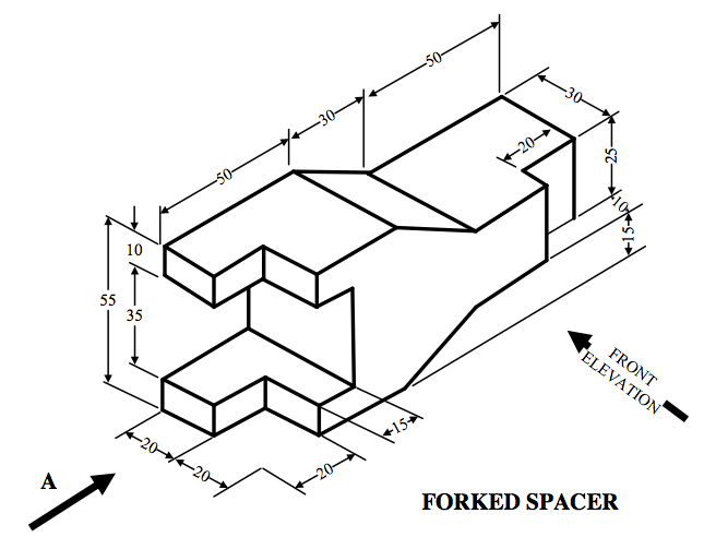
- The drawing should be correctly laid out with the correct projection method (3rd angle), details of the projections, title box, clarity, dimensions, neatness and comprehensiveness.
Exercise 2:
- Draw the three Orthographic views of the Cast Cleat using Third Angle Projection to a scale of half full scale (1:2). The cleat should be viewed in the directions indicated in the figure below.
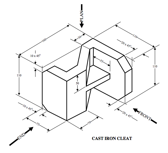
- The drawing should be correctly laid out with the correct projection method (3rd angle), details of the projections, title box, clarity, dimensions, neatness and comprehensiveness.
-
17 - 3rd Angle Orthographic Projection cont.
- Ex 17.1:
- Draw the three Orthographic views of the component using Third Angle Projection to full scale (1:1). The part should be viewed in the directions indicated in the figure below.
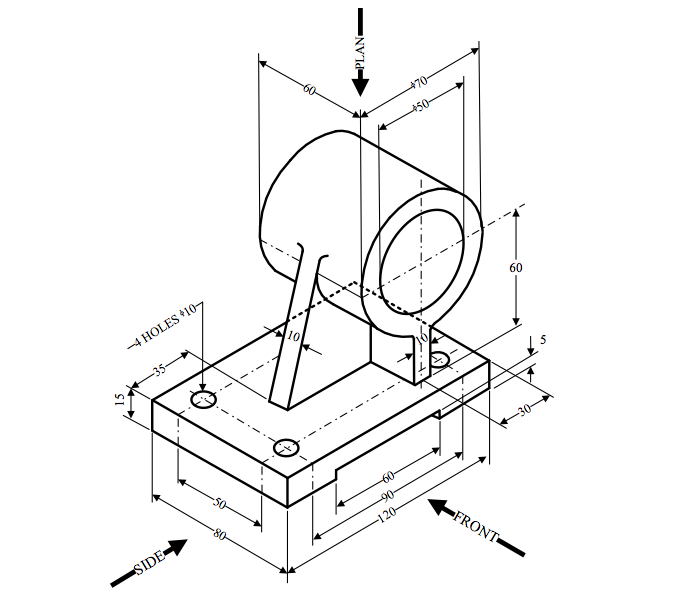
- All dimensions in mm.
- The drawing should be correctly laid out with the correct projection method (3rd angle), details of the projections, title box, clarity, dimensions, neatness and comprehensiveness.
-
material goes here