03
-
Procedure for PCB Assembly
- 1. Check PCB for errors.
2. Insert and solder links.
3. Insert and solder the four resistors.
4. Insert and solder the 14 pin IC socket.
5. Insert and solder the capacitor.
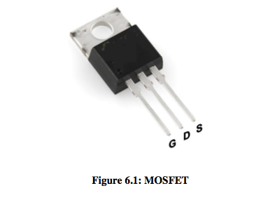
6. Insert and solder the two P-type MOSFET’s. (Q3 and Q4; P/N FQP17P06), Figure 6.1 shows a MOSFET.
7. Insert and solder the two N-type MOSFET’s. (Q1 and Q2; P/N IRL3215).
8. Insert the logic IC into the socket.
9. Cut six 30 cm lengths of multi-strand connecting wire and solder to the appropriate pad hole.
Black 0 volts Red +5 volts Green enable Blue fwd/rev Yellow Motor + Yellow Motor –
10 Test the assembled PCB with a motor and a power supply.
Connect 0 and 5V to power supply.
The motor should rotate in 1 direction.
Set the green wire (enable) low (to 0V) and the motor should stop.
Set the green wire high (to 5V) and the motor should rotate again.
Connect the blue wire to +5V and the motor should rotate in the opposite direction
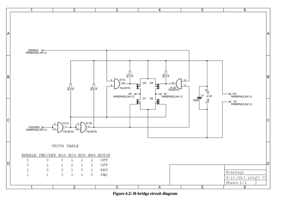
H-bridge Circuit Diagram
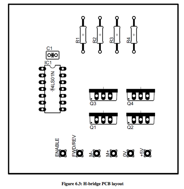
H-bridge PCB Layout
- PCB Assembly - Demonstration Video 📹
- PCB Assembly - Demonstration Video
- Please stop the video before closing the lightbox
- 1. Check PCB for errors.
-
Electrical Measurement (DMMs) Digital Multimeters
- Introduction
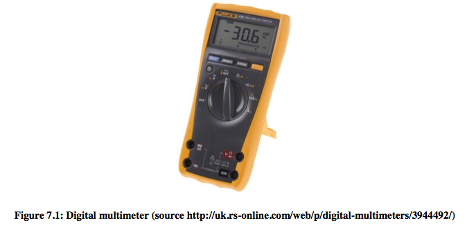
A multimeter is an electronic measuring instrument that can measure voltage, current and resistance. A multimeter also can be used for some basic checks and troubleshooting; is the circuit working, is the particular component working, and etc. Figure 7.1 shows a digital multimeter. In the recent past, Digital Multimeters commonly become available and these instruments have a numeric display, and may also show a graphical bar representing the measured value. But, still in some preferable cases, such as monitoring a rapidly varying value analog multimeter are used.
Parts of a Multimeter
Display The display usually has four digits. Selection knobs Depending on the different readings such as milliamps (mA) of current, voltage (V) and resistance (Ω), different knobs could be used. Ports On the front of the multimeter, two probes are plugged into two ports. COM (stand for common) probe, conventionally black, is connected to ground or ‘_’ of a circuit. Red probe allows the measurement of current (A), voltage (V) and resistance (Ω).
Measuring Voltage
Example: measure voltage on AA battery.
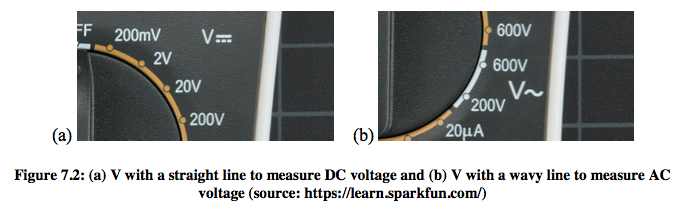
In general, portable electronics use direct current (DC). Chose the correct scale (200mV, 2V, 20V, etc.) and connect the black probe to the battery’s ground (‘_’). Connect the red probe to power (or ‘+’) which are the negative and positive terminals of the battery. Now you will get the reading on the display (if it is a fresh battery reading should be around 1.5V).
Multimeters are used to measure both DC voltage and AC voltage. As shown in Figure 7.2, depending on the direct or alternative current you need to set the knob where the V has a straight line or with a wavy line. In general, multimeters are not autoranging, as such, user has to set the multimeter to a range that it can measure. For example, 20V measures voltages up to 20 volts.
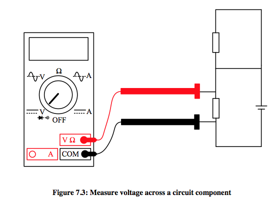
A multimeter can be used to test different parts of the circuit. By measuring the voltage across the different components of the circuit how much voltage each component requires can be measured as illustrated in Figure 7.3.
Measuring Resistance
Example: measure the resistance of a resistor.
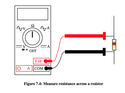
Resistors normally have colour codes on them which could use to identify the resistance. However, a multimeter can be used to measure the resistance of a resistor as shown in Figure 7.4. The meter probes can be connected to either side of the resistor. In order to measure the resistance the resistor must first be isolated (removed) from the circuit to ensure that the other components in the circuit do not affect the reading.
The multimeter will read three types of reading.
A. If the multimeter is overloaded it displays 1 or OL.
B. If the meter reads 0.00 or nearly zero indicated to lower the range.
C. Or, meter reads the actual value.
Measuring Current
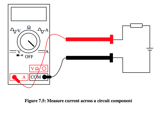
Reading current is slightly difficult and sensitive as current has to measure in series. The rate of flow of electrons through the circuit is measured as the current. To measure the current through a component, the circuit must be broken (physically interrupt) and the meter must be placed such that the current flows through it as illustrated in Figure 7.5. After connecting the multimeter correctly to the circuit set the dial to the proper setting and measure the current. As reading the voltage and resistance it is important to select the correct range.
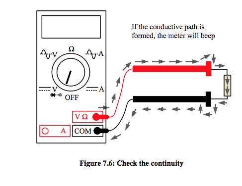
Continuity
It is essential to check that the circuits are continuous, allowing current to flow. Fuses, switches, wire connectors and etc. demand good continuity, if your eyes can not see it. The continuity test on a Digital Multimeter is simple (see Figure 7.6) Ensure that the power is off. Set the meter to continuity function and plug in probes where continuity of the circuit should check. If two points are connected electrically a tone is emitted.
Exercise:
1. Measure the resistance of different resistors, voltage of AA battery, current in a simple circuit and continuity of different connections of a circuit.
2. Write a report based on DMM functions and characteristics and also understand and apply the concepts of measurement accuracy and measurement precision (number of words – not less than 1000).
- Introduction