04
-
- Electrical Measurement (DSOs - Digital Storage Oscilloscopes)
- Introduction - Oscilloscope Fundamentals
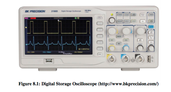
This section covers Oscilloscope Fundamentals. Voltage and timing measurements on analog and digital electrical circuits can measure using Oscilloscopes. And also Oscilloscopes are used to test, verify, and debug your designs. Digital Storage Oscilloscope is shown in Figure 8.1. After studying this section on the fundamentals of oscilloscopes, and after completing the hands-on labs using the Digital Storage Oscilloscope you should develop a better understanding of what a scope is and how to use one effectively.
What is an oscilloscope
Oscilloscopes convert electrical signals into a visible trace on a screen/display. An oscilloscope is an electronic instrument that known as a scope, CRO (for cathode-ray oscilloscope), or DSO (for the more modern digital storage oscilloscope). It allows observation of constantly varying signal voltages as a function of time, and additional signals (such as sound or vibration) can be converted to voltages and displayed. Oscilloscopes observe the change of an electrical signal over time; voltage and time describe a shape which is continuously graphed against a standardised scale. Based on the waveform can be examined for such properties as frequency, amplitude, rise time, time interval, distortion and others.
Oscilloscopes are dynamically used to graph time-varying electrical signals in two dimensions. Scope is the most commonly used terminology and generally, on the vertical axis of the scope’s display voltage is plotted, while time is plotted on the horizontal axis.
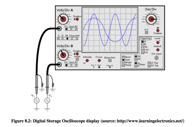
Most oscilloscopes have at least two vertical inputs. These inputs are displayed more than one waveform simultaneously as illustrated in Figure 8.2.
Oscilloscope – Probes
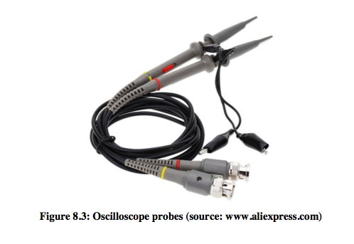
Typical Oscilloscope probes, as illustrated in Figure 8.3, will have pointy stick, the alligator clip; the input attenuation circuitry and impedance matching circuitry inside. It is important to mention that getting the desired signal to be tested into the scope’s input BNC (Bayonet Neill–Concelman) connectors in order to measure electrical signals on an oscilloscope. Depending on the purpose such as high frequency applications, high voltage applications, and current measurements the probe type can be varied.
Oscilloscope probes can be categorised into two main types, namely Passive oscilloscope probes (most widespread use) and Active oscilloscope probes, this type of scope probe has active components combined within the probe itself. To minimize loading, attenuator probes, such as 10X probes are used. To measure the output of generator can achieve connecting the output of the generator directly to the input of the scope using a standard 50-Ω BNC or SMA cable. Further, the most common type of oscilloscope probe used in everyday life to test a broad range of signals is called a “passive 10-to-1 voltage divider probe”.
Oscilloscope – Understanding the Scope’s Display
Once the probes are setup, the oscilloscope displays captured waveforms. These waveforms are in a X versus Y format. The horizontal axis (X-axis) represents time and the voltage is plotted on the vertical axis (Y-axis).
So if the scope is set to 1 volt/major vertical division and 0.5 seconds/major horizontal division, then a point situated at the 2-dimensional coordinates of 2 major vertical divisions plus 2 minor vertical division and at 3 major horizontal divisions plus 4 minor horizontal divisions would represent a 2.4 volts (or 1 volts/major vertical division times 2 major vertical division plus 1 volts/major vertical division times 2/5 major divisions [which is equal to 2 minor vertical divisions]) at a position of time of 1.9 seconds (or 0.5 seconds/major horizontal division times 3 major horizontal divisions plus 0.5 seconds/major horizontal division times 4/5 major divisions [which is equal to 4 minor horizontal divisions]) from the start of the waveform (https://web.njit.edu/~joelsd/electronics/Labs/oscilloscopelabnew.pdf).
Oscilloscope Fundamentals – Application notes
An overview of oscilloscope fundamentals is highlighted in the attached notes (Basic Oscilloscope Operation Q&A). The notes will give you an overview of basic measurements and performance characteristics of an Oscilloscope and different types of probes and discuss their advantages and disadvantages.
Oscilloscope Tutorial
1. Study the digital oscilloscope and write a report on basic Oscilloscope functions (number of words – not less than 1000).
2. Using the voltmeter, measure the output voltage, Vout, vs input voltage, Vin, (use the 9 volt batteries for Vin ) for the following values of R1 and R2:
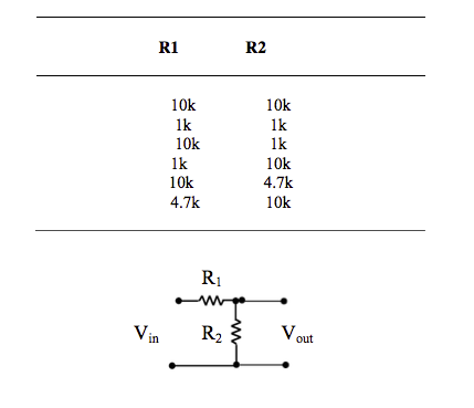
3. For the following circuits using the oscilloscope, determine the transfer function for frequencies of 0 to 800Hz in steps of 50 Hz. -
Arduino Programming – I
- ARDUINO MAKES IT AS EASY AS POSSIBLE TO PROGRAM TINY COMPUTERS CALLED MICROCONTROLLERS, WHICH ARE WHAT MAKE OBJECTS INTERACTIVE
You are surrounded by dozens of them every day: they are embedded in timers, thermostats, toys, remote controls, microwave oven some toothbrushes. They just do one specific task, and if you hardly notice them – which is often the case – it`s because they are doing it well. They have been programmed to sense and control activity using sensors and actuators.
Sensors listen to the physical world. They convert energy that you give off when you press buttons, or wave your arms, or shout, onto electrical signals. Buttons and knobs are sensors that you touch with your fingers, but there are many other kinds of sensors.
Actuators take action in the physical world. They convert electrical energy back into physical energy, like light and heat and movement.
Microcontrollers listen to sensors and talk to actuators. They decide what to do based on a program that they write.
Microcontrollers and the electronics you attach to them are just the skeleton of your projects, though. You`ll need to bring skills you probably already have to put some flesh on the bones.
For example, in one of the projects we suggest, you`ll make an arrow and attach it to a motor, and put them both in a box with a knob, so you can make a meter to tell people whether you`re busy or not. In another, you`ll put some lights and a tilt switch on a cardboard frame to make an hourglass.
Arduino can make your projects responsible, but only you can make them beautiful. We`ll proved some suggestions along the way as to how you might do that.
Arduino was designed to help you get things done. To make that happen, we kept the background material on programming and electronics to a minimum. If you decide you want to know more about these aspects, there are lots of good guides available. We`ll provide a couple of references, and you can find more online at: Arduino.cc/starterkit.
- Text espoused from The Arduino Projects Book - ARDUINO MAKES IT AS EASY AS POSSIBLE TO PROGRAM TINY COMPUTERS CALLED MICROCONTROLLERS, WHICH ARE WHAT MAKE OBJECTS INTERACTIVE
-
Introduction to Arduino Programming
- 'Arduinos' are microcontrollers (tiny computers) that are designed for use in a wide array of applications. Many projects that require an embedded system with some level of intelligence can use an Arduino module as the controller such as washing machines, microwave ovens, electronic games and robotic toys.
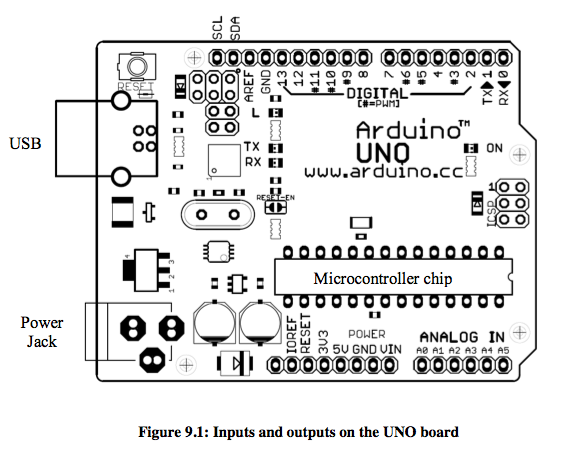
Each Arduino board includes a microcontroller chip with internal memory (RAM, EPROM and flash), a 5 volt regulator, and has a number of general purpose INPUT / OUTPUT pins. The basic Arduinos are capable of running a few thousand instructions per second and are programmed with the Arduino programming language (based on the C programming language but with many additional easy-to-use instructions). Some boards have a USB connector which can be used to connect the board to a PC to provide power and to upload your programs onto the Arduino board.
Arduino programs are created on a PC using the Arduino integrated development environment (IDE). The IDE allows you to (a) write your program, (b) compile it (i.e. convert it to code that the actual microcontroller chip on the Arduino board can understand) and (c) upload the compiled code onto the Arduino board. The IDE can be freely downloaded from the Arduino web site (http://arduino.cc/en). It includes a full reference on the Arduino programing language as well as several tutorials. There is also a lot of information about Arduino on the web as it is a very popular platform.
There are many models of Arduino boards. We will use the Arduino UNO. Below is a simplified diagram (Figure 9.1) of the inputs and outputs on the UNO board. It has six analogue inputs, and 12 digital input / output (I/O) pins (usually Tx and Rx are not used).
For additional information refer to the book Arduino Cookbook by M. Margolis, which is available in the library both as a paper copy and as an electronic book online. - 'Arduinos' are microcontrollers (tiny computers) that are designed for use in a wide array of applications. Many projects that require an embedded system with some level of intelligence can use an Arduino module as the controller such as washing machines, microwave ovens, electronic games and robotic toys.
-
Get to Know Your Tools
- In this workshop you will make a simple circuit with some switches, an LED and a resistor.
After completing this session you will learn about the electrical properties of voltage, current, and resistance while building a circuit on a breadboard. With some components like LEDs, resistors and switches, you will create the simplest interactive system: a user presses the button, the lights turn on. These fundamentals of working with electronics will be referenced and expanded upon in the upcoming projects.
Information of this workshop:
Source: 
Section: 01 | Pages 20 - 31 Video: Arduino Tutorial 1
Spaceship Interface
- In this workshop you will develop your first programme.
After completing this project you will create your first Arduino program to control the behaviour of some LEDs based on a switch. You will use variables, an if()...else statement, and functions to read the state of an input and control outputs.
Information of this workshop:
Source: Section: 02 | Pages 32 - 41 Video: Arduino Tutorial 2
- In this workshop you will make a simple circuit with some switches, an LED and a resistor.