03
-
- Hydrostatic pressure and manometers
- 3.1 Introduction
- This section will study the forces acting on or generated by fluids at rest. This understanding of pressure will then be used to demonstrate methods of pressure measurement that will be useful later with fluid in motion.
-
- 3.2 Objectives
- ●Introduce the concept of pressure;
●Prove it has a unique value at any particular elevation;
●Show how it varies with depth according to the hydrostatic equation
●Show how pressure can be expressed in terms of head of fluid.
●Describe the different types of manometers
-
- 3.3 Hydrostatics:
- Hydrostatics deals with the study of fluids at rest and in equilibrium (like statics in mechanics). Net forces are zero, and there is no flow.
3.3.1 Pascal’s Law for pressure at a point in a fluid at rest
Consider the equilibrium of a small fluid element in the form of a triangular prism in the fluid subject to a pressure px in x-direction, py in y-direction and ps in normal to any plane inclined at an angle θ to the horizontal.
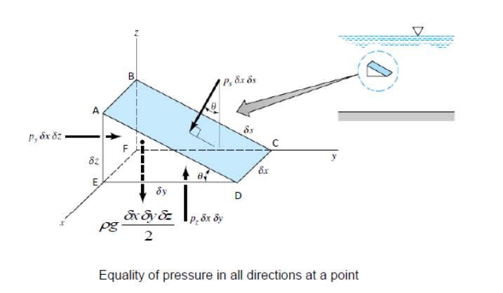
The fluid is at rest, so we know there are no shearing forces and all forces acting at right angles to the surfaces.
For simplicity, the forces in the z direction are not shown.
3.3.2 Variation of pressure in a fluid under gravity
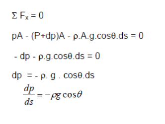
The fundamental equation of fluid statics is that relating pressure, density and vertical distance in a fluid. Consider the cylindrical element of fluid in the figure below, inclined at an angle θ to the vertical, length ds, cross-sectional area A in a static fluid of mass density ρ.
The pressure at the end with height z is p and at the end of height z +dz is p +dp .
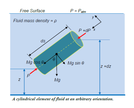
This equation may be derived by considering the static equilibrium of a typical differential element of fluid (Figure below).
The fluid is at rest and in equilibrium, applying Newton’s first law (ΣFx = 0 and ΣFy = 0) to the element
Forces acting in the x-direction parallel to the centre line of the fluid element
Force due to P on A = PA Force due to (P+dP) on A = (P+dP) A Force due to weight of element = Mg cos θ
Since the Mass of element = Mass density × Volume = p A.ds, thus Force due to the weight of the element = p.A.g.cosθ.ds
There are also forces from the surrounding fluid acting normal to these sides of the element. For equilibrium of the element the resultant of forces in any direction is zero. Resolving the forces in the direction along the central axis gives
Thus, in any fluid under gravitational attraction, pressure increase with increase in depth. Let us consider two specific cases:
1. When θ = 0o , [If θ = 0o then s is in the z direction (vertical)]
2. When θ = 90o [If θ = 90o then s is in the x or y directions, (i.e. horizontal)]
Case 1:
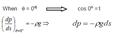
In a liquid with a free surface the pressure at any depth z measured from the free surface so that z = -h
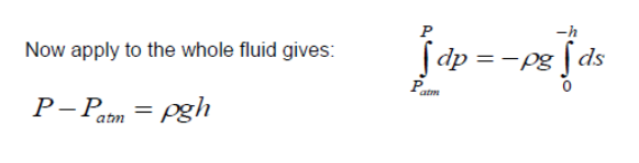
For all pressure measurements atmospheric pressure is always taken as the reference pressure i.e Patm = 0
Thus the above equation becomes:
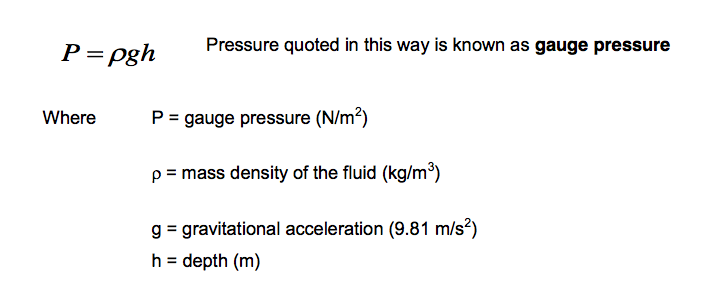
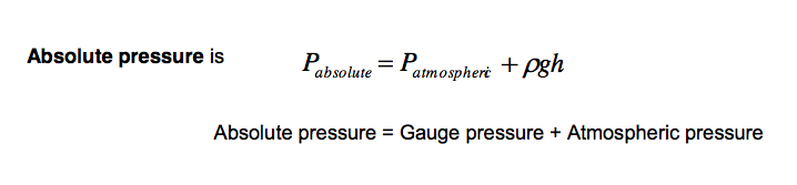
The lower limit of any pressure is zero - that is the pressure in a perfect vacuum. Pressure measured above this datum is known as absolute pressure i.e.
Example:
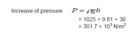
A diver descends from the surface of the sea to a depth of 30m. Determine the pressure under which the diver would be working above that at the surface assuming that the density of sea water is 1025 kg m-3 and remains constant.
Solution
In equation P = Pgh , taking sea level as datum, h = 30m. Substituting these values andputting p = 1025kg/m3.
-
- 3.4 Absolute, gauge and vacuum pressure
- Absolute pressure is the pressure measured relative to a total vacuum, and thus is always positive. We often measure pressures relative to the local atmospheric pressure (e.g. the pressure underwater in the above example) and this is known as the gauge pressure. Since pressure differences are what gives net forces, subtracting a constant reference pressure is not generally important in fluid dynamics (but we need the absolute pressure for the gas equation). If the pressure is less than atmospheric pressure but given as relative to atmospheric pressure this is sometimes referred to as a vacuum pressure (e.g. a vacuum pressure of 10 kN/m2 is a pressure of 10 kN/m2 below atmospheric pressure, or a gauge pressure of -10kN/m2).
Case 2:
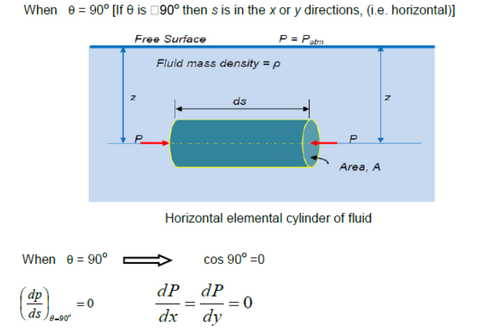
Pressure in the horizontal direction is constant.
This result is the same for any continuous fluid. It is still true for two connected tanks which appear not to have any direct connection, for example consider the tank in the figure below.
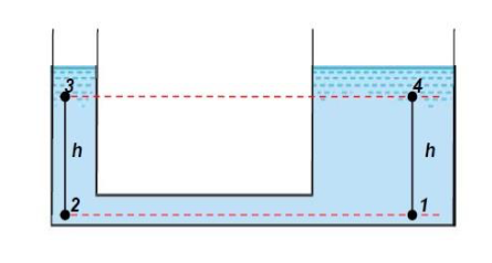
Two tanks of different cross-section connected by a pipe
We have shown above that pressure in the horizontal direction is constant (i.e. P1 = P2 ) and from the equation for a vertical pressure change we have
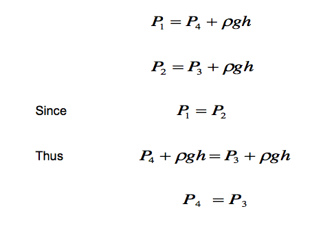
This shows that the pressures at the two equal levels, 3 and 4 are the same provided that the two equal levels lie in the same continuous body of fluid.
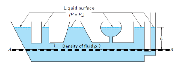
The pressure in the fluid does not depend on the size or shape of the container. It only depends on the position below the free surface h, the pressure at the interface pa and the density of the fluid.
Hydrostatic paradox: The pressure depends only on the depth of the fluid not on the shape of the container, so at the same depth the pressure is the same in all parts of the container. In the figure below the pressure is equal along the line AB
-
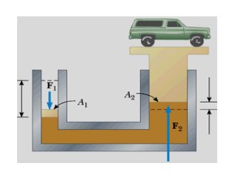
- 3.5 Hydraulics
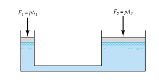
- Hydrostatic equation also applies when external forces are applied at the fluid interface.
● P(piston1) = P(piston2) (if at equilibrium).
● P = P(piston1) + ρgh . The pressure from the piston head is transmitted to all points in the fluid.
● F1/A1 = F2/A2 . A small force applied to a small area can be used to apply a large force to a large area.
Example:
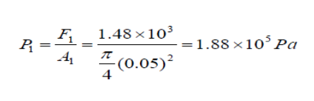
In a car lift used in a service station, compressed air exerts a force on a small piston that has a circular cross section and a radius of 50 mm. This pressure is transmitted by a liquid to a piston that has a radius of 150 mm. Determine the force that the compressed air must exert to lift a car weighing 13,300N. Also determine the air pressure produces this force.
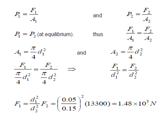
Therefore the necessary pressure of the compressed air is
-
- 3.6 Pressure head
The pressure difference between two points (see figure below) can be specified by vertical distance, h between those points.
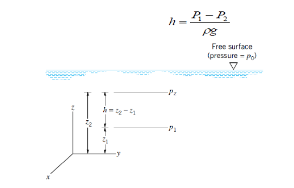
So h is called the pressure head. We can say that a pressure difference of 60, 000 Pa has a pressure head of 6.12 m of water or 0.450 m of mercury. The pressure head is the depth of fluid that would exert an equivalent pressure difference.
Note that when pressures are expressed as head it is essential that the mass density p is given or the fluid named. For example, since from equation h = p/pg a pressure of 100 kN m-2 can be expressed in terms of water (pH2O = 103 kg m-3) as a head of (100 x 103)/(relative density 13.6) a pressure of 100 kN m-2 will correspond to a head of (100 x 103)/(13.6 x 103)(13.6 X 103 x 9.81) = 0.75 m of mercury.
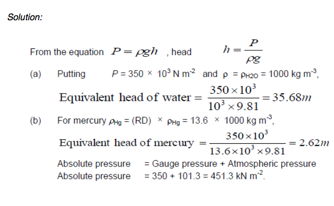
Example:
A cylinder contains a fluid at a gauge pressure of 350 kN m-2. Express this pressure in terms of a head of (a) water (pH2O = 1000 kg m-3), (b) mercury (relative density RD=13.6). Determine the absolute pressure in the cylinder if the atmospheric pressure is 101.3 kN m-2.
-
- MANOMETERS
- 3.7.1 Pressure tube or piezometer
The relationship between pressure and head is utilized for pressure measurement in the manometer or liquid gauge. The simplest form is the pressure tube or piezometer shown in the figure below, consisting of a single vertical tube, open at the top, inserted into a pipe or vessel containing liquid under pressure which rises in the tube to a height depending on the pressure. If the top of the tube is open to the atmosphere, the pressure measured is ‘gauge’ pressure:
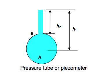
Pressure at A = Pressure due to column of liquid of height h1, pA = pgh1 Similarly Pressure at B = Pressure due to column of liquid of height h2, pB = pgh2
If the liquid is moving in the pipe or vessel, the bottom of the tube must be flush with the inside of the vessel; otherwise the reading will be affected by the velocity of the fluid. This instrument can only be used with liquids, and the height of the tube which can conveniently be employed limits the maximum pressure that can be measured. The piezometer is only useful when the pressure to be measured is greater than atmospheric (otherwise) air would be sucked back into system.
Example
What is the maximum gauge pressure of water that can be measured by means of a piezometer tube 2 m high? (Mass density of water pwater = 103 kg m-3).
Solution
Since p = pgh for maximum pressure,
put p = pwater = 103 kg m-3 and h = 2m, giving Maximum pressure,
P = 103 x 9.81 x 2 = 19.62 x 10³ N m-2.
3.7.2 U-tube manometer
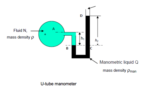
The U-tube gauge, shown in the figure above, can be used to measure the pressure of either liquids or gases. The bottom of the U-tube is filled with a manometric liquid “Q”, which is of greater density p, whose pressure is to be measured. If B is the level of the interface in the left-hand limb and C is a point at the same level in the right- hand limb,
Pressure PB at B = Pressure PC at C.
For the left-hand limb,
PB = Pressure PA at A + Pressure due to depth h1 of fluid N
PB = PA + pgh1
For the right-hand limb,
PC = Pressure PD at D + Pressure due to depth h2 of fluid Q
But PD = Atmospheric pressure = Zero gauge pressure
and so PC = 0 + pmangh2
Since PB = PC,
PA = pmangh2 - pgh1 = g(pmanh2 - ph1)
Example:
A U-tube manometric similar to that shown in the figure above is used to measure the gauge pressure of a fluid N of densityp = 800 kg/m3. If the density of the liquid Q is 13.6 x 10³ kg/ m3, determine the gauge pressure at A if (a) h1 = 0.5 m and h2 = 0.9 m above BC, (b) h1 = 0.1m and the free surface is 0.2 m below BC.
Solution
(a) In equation (2-1), pman = 13.6 x 10³ kg m-3, p = 0.8 x 10³ kg m-3,
h1 = 0.5 m, h2 = 0.9 m, therefore:
PA = 13.6 x 103 x 9.81 x 0.9 - 0.8 x 103 x 9.81 x 0.5 = 116.15 x 10³ Nm-2
(b) Putting h1 = 0.5 m and D is 0.9 m above BC, h1 = 0.1 m and D is 0.2 m below BC?
PA=9.81{13.6 x 10³ x (-0.2) - 0.8 x 103 x 0.1}
PA =-27.45 x 10³N/m2,
The negative sign indicating that PA is below atmospheric pressure.
3.7.3 Measurement of pressure difference
In Fig,. 2.9, a U-tube gauge is arranged to measure the pressure difference between two points in a pipeline. As in the previous case, the principle involved in calculating the pressure difference is that the pressure at the same level CD in the two limbs must be the same, since the fluid in the bottom of the U-tube is at rest.
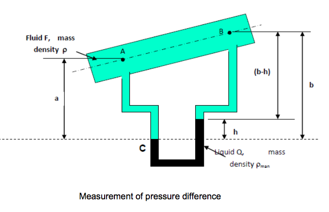
For the left-hand limb,
PC =PA + pga
For the right-hand limb,
PD =pB + pg(b-h)+ pmangh
Since PC = PD,
PA + pga=PB + pg(b-h)+ pmangh,
Pressure difference = ΔP = PA - PB = p g(b - a) + h g (pman - p)
When the pipeline is horizontal a = b, thus
Pressure difference = ΔP = PA - PB = h g (pman - p)
Example
A U-tube manometer is arranged, as shown in Fig. 2.9, to measure the pressure difference between two points A and B in a pipeline conveying water of density pH2O = 103 kg m-3. The density of the manometric liquid Q is 13.6x10³ kg m-3, and point B is 0.3 m higher than point A. Determine the pressure difference, when h = 0.7 m.
Solution
p = 103 kg m-3, pman = 13.6 × 10³ kg m-3, (b - a) = 0.3 m, and h = 0.7 m.
Pressure difference = ΔP = PA - PB = p g (b-a) + h g (pman - p)
= 103 × 9.81 × 0.3 + 0.7 × 9.81(13.6×10³-103)
= 89.467 ×10³ Nm-2
In both the above cases, if the fluid F is a gas its density p can usually be treated as negligible compared to pman and the equations (2-2) and (2-3) can be simplified.
In forming the connection from a manometer to a pipe or vessel in which a fluid is flowing, care must be taken to ensure that the connection is perpendicular to the wall and flush internally. Any burr or protrusion on the inside of the wall will disturb the flow and cause a local change in pressure so that the manometer reading will not be correct.
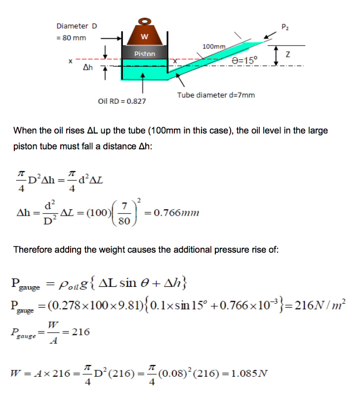
3.7.4 Inclined Manometer
Industrially, the simple U-tube manometer has the disadvantage that the movement of the liquid in both limbs must be read. By making the diameter of one leg very large as compared with the other (see figure below), it is possible to read the movement of the liquid in the narrow leg. Assuming that this manometer is used to measure the pressure difference( P1 - P2) in a gas of negligible density and the XX is the level of the liquid surface when the pressure difference is zero, then, when pressure is applied, the level in the right-hand limb will rise a distance z vertically.
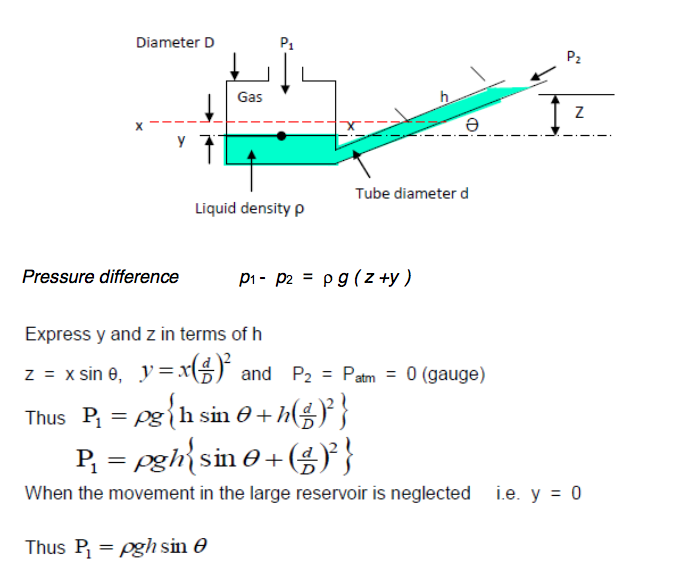
The manometer can be made as sensitive as may be required by adjusting the angle of inclination of the leg and choosing a liquid with a suitable value of density p to give a scale reading x of the desired size for a given pressure difference.
Example
An 80mm diameter piston compresses oil in to an inclined manometer tube as shown in figure below. Given that a weight W is added to the piston, the oil rises an additional 100mm up the tube, determine the value of W in Newtons.
3.7.5 Choice of Manmeter
Care must be taken when attaching the manometer to vessel; no burrs must be present around this joint. Burrs would alter the flow causing local pressure variations to affect the measurement.
Some disadvantages of manometers:
● Slow response - only really useful for very slowly varying pressures - no use at all for fluctuating pressures;
● For the “U” tube manometer two measurements must be taken simultaneously to get the h value. This may be avoided by using a tube with a much larger cross-sectional area on one side of the manometer than the other;
● It is often difficult to measure small variations in pressure - a different manometric fluid may be required - alternatively a sloping manometer may be employed; It cannot be used for very large pressures unless several manometers are connected in series;
● For very accurate work the temperature and relationship between temperature and r must be known;
Some advantages of manometers:
● They are very simple.
● No calibration is required - the pressure can be calculated from first principles
Week 3 Activities 1-6
-
- Summary
This week, we introduced the concept of pressure and proved that it has a unique value at any particular elevation.
We showed how it varies with depth according to the hydrostatic equation and how pressure can be expressed in terms of head of fluid. We also introduced and understood the different types of manometers, their advantages and disadvantages. -
-