04
-
Introduction
- This week we will be looking at the defect in crystals, namely point and line defects. We will look at how these change the properties of the parent material.
Study Plan
- 1. Read through the lecture summary (page 18, 3-5)
2. Read over week 4 lecture presentation
3. Read chapter 4.1-4.3, 4.5-4.7, 7.2, and 7.4 in Callister
4. Work through the rest questions on page 29 of the study pack and other relevant questions at the end of the chapter in Callister
Activity: 1. Look at the videos referenced in the study pack
Activity: 2. View the VMSE on Dislocations - This week we will be looking at the defect in crystals, namely point and line defects. We will look at how these change the properties of the parent material.
-
- Lattice Defects
- Before we proceed I would like you to have a look at this video on miller indices
So far we have looked at the structures of perfect crystals. We will now move on to discuss the possible crystal imperfections. i.e. crystals with flaws. There are two major types of imperfections called DEFECTS.
1. POINT DEFECTS
2. LINE DEFECTS
Point Defects
These are formed by either an extra atom or ion occupying an otherwise vacant site called an INTERSTITIAL site. There are two main types:
tetrahedral : vacancy surrounded by four atoms.
octahedral : vacancy surrounded by six atom.
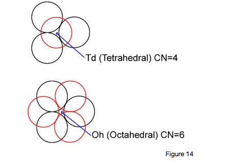
The point defect may take the form of either an extra atom in one of these interstices or an extra vacancy formed in the lattice. These, cumulatively, produce stresses throughout the lattice.
Line Defects
These imperfections consist of defects which are considerably larger than the point defects discussed above, as they may extend over many atomic distances. These generally take the form of DISLOCATIONS. A dislocation, as the term literally implies, is an interruption in the periodicity of the lattice which puts the crystal out of order. This type of line defect can be created during crystallisation, when there is a mismatch in crystallographic orientation, or a break in periodicity of the growth crystal. And also during deformation of the crystals in a solid engineering material, when subjected to forces which permanently change their shape - this is termed plastic deformation.
There are two types of line dislocation:
1. Edge type
2. Screw type
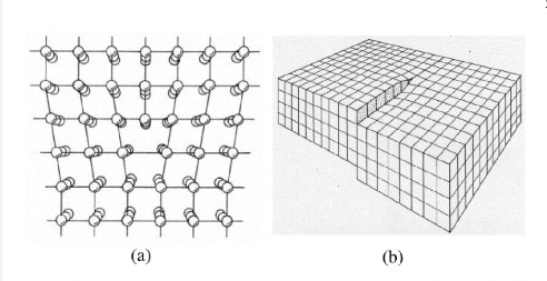
Edge Type
This can be considered as an extra plane of atoms inserted into a perfect crystal.
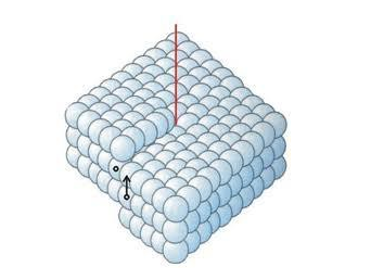
Screw Type
This is the case where a dislocation is produced by skewing a crystal so that one atomic plane produces a spiral ramp about the dislocation.
BURGERS VECTOR : This is the extent of lattice displacement, amount and direction, required to close a loop around the crystal.
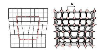
When a shear force acting along the direction of the Burgers vector is applied to a crystal containing a dislocation, the dislocation can move by breaking the bonds between the atoms in one plane. The cut plane is shifted slightly to establish bonds with the original plane of atoms. This causes the dislocation to move one atom spacing to the side, this continues until a slip is produced.
The process by which a dislocation moves and causes a metal to deform is called SLIP. The direction in which the dislocation line moves, the SLIP DIRECTION is the direction of the Burgers vector for edge dislocations. During slip the edge dislocation sweeps out the plane formed by the Burgers vector and the dislocation, this plane is called the SLIP PLANE. The combination of slip direction and slip plane is the SLIP SYSTEM. A screw dislocation produces the same result. The dislocation moves in a direction perpendicular to the burgers vector, although the crystal deforms in a direction parallel to the burgers vector. Whenever possible, the slip direction is a close-packed direction. The most common slip systems in metals are:
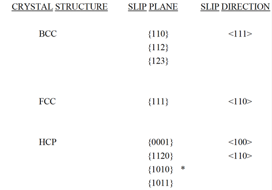
* active only in some metals, alloys & at elevated temperatures
The significance of dislocations is that although slip can occur in some ceramics and polymers, the slip process is particularly helpful in understanding the mechanical behaviour of metals.
Firstly, slip explains why the strength of metals is much lower than the value predicted from the metallic bond. If all of the metallic bonds had to be broken in order to fracture an Iron bar.
Then a force of thousands of MPa would be required to deform the bar, however only a small fraction of this would be required to deform the bar by slip i.e. 4 - 5 MPa.
Secondly, slip provides ductility in metals. If no dislocations were present, the iron bar would be brittle, metals could not be shaped by the various metal working processes, such as forging, into useful shapes.
Thirdly, it is possible to control the mechanical properties of a metal by interfering with the movement of dislocations. An obstacle introduced into the crystal prevents a dislocation from slipping unless a greater force is applied, therefore, the metal must be stronger.
Have a look at these videos mechanism consequences
Summary of the influence of crystal structure
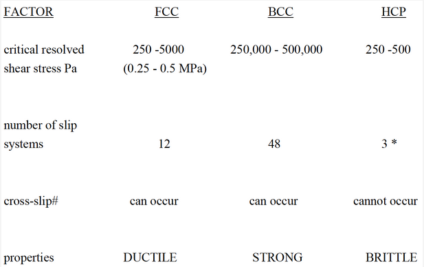
# cross-slip
Suppose a dislocation moving in one slip plane encounters an obstacle and is blocked from further movement. The dislocation can shift to a second intersecting slip system, also properly orientated, and continues to move. This is called CROSS- SLIP. HCP cannot do this as the slip planes are parallel, therefore HCP remain brittle. However, additional slip systems (*) become active when HCP metals are alloyed or heated, thus improving ductility. Cross-slip is possible in both FCC and BCC metals due to the number of intersecting slip systems present. This helps to maintain ductility in these metals.
Dislocations can also interact constructively or destructively. -
CRYSTAL STRUCTURES/MILLER INDICES/DISLOCATIONS: LECTURE SUMMARY
- In the course of this lecture, you will learn that atoms can form into three dimensional structures.
In the case of metal atoms, these take the form of three main types of UNIT CELL: Face centered cubic (FCC); Hexagonal close packed (HCP) and Body centered cubic (BCC).1. The number of atoms per unit cell for each of the main types of arrangement are:
FCC : 4
HCP : 6
BCC : 2
Unit Cell parameter:
FCC: 4r/√2
BCC: 4r/√3
2. The miller index of a particular plane is determined by reciprocal of the intercept of the plane with the three principal axes: i.e.
h= 1/x
k= 1/y
l= 1/z
3. There are two main types of dislocation which occur in metals:
a) Edge dislocation: extra half plane of atoms inserted in the structure,
b) Screw dislocation: skewering of the crystal around an axis.
4. The significance of dislocations are that:
i) The observed tensile strength of the metal is much lower than that calculated e.g. steel 100's MPa rather than 1000's MPa.
ii) Metals are ductile.
iii) The mechanical properties of the metal can be altered by heat treatment. - In the course of this lecture, you will learn that atoms can form into three dimensional structures.
-
-
- CRYSTAL STRUCTURE AND LATTICE DEFECTS TUTORIAL
1. (a) Determine the unit parameter for the Face Centred Cubic unit cell in terms of rthe atomic radius, and hence determine the theoretical density of a metal crystallising in the FCC unit cell configuration.
(b) Copper has a FCC crystal structure and its atomic weight equals 63.54g. If the approximate atomic radius of Cu is 0.1278nm, determine its density.
(c) Copper has an observed density of 8.90 gcm-3. Discuss any discrepancy between this value and that determined in (b) above.
(NA= 6.02 x 10²³ )
2. Determine the unit parameter for the Body Centred Cubic unit cell in terms of r the atomic radius, and hence determine the theoretical density of a metal crystallising in the BCC unit cell configuration.
(b) Iron has a BCC crystal structure below ~900oC, and its atomic weight equals 55.847g. If the approximate atomic radius ofFe is 0.1238nm, determine its density and describe why this differs from the experimental value of 7.87 gcm-3.
(NA= 6.02 x 10²³ )
(c) State the threesignificant factors associated with dislocations in metals.
3. (a) Determine the percentage volume change when Iron cools from 1000oC (FCC) to 800oC (BCC)
(b) Determine the Packing Factor for both FCC and BCC unit cells.
4. Draw the following planes:
(100), (101), (011), (111), (110), (010) and (001)
5. (a) Describe the TWO main types of line defects which occur in metals
(b) Explain how these defects affect the mechanical properties of the metal
- Click here for solution 📷