06
-
- The Steady Flow Energy Equation (SFEE) for Incompressible Flow
- 6.1 Introduction
- This section continues the discussion of fluid in motion - fluid dynamics. Considering energy losses due friction, the Bernoulli equation has to be modified in order to comply with the energy and mass conservation laws. The Steady Flow Energy Equation (SFEE) is often used to calculate the power needed to maintain a certain flow rate with a pump or the power generated by a hydro-power station. In this section we are going to introduce you to these basic calculations.
-
- 6.2 Objectives
- • Introduce the Steady Flow Energy Equation (SFEE)
• Describe the nature of the energy losses, especially the friction losses
• Demonstrate practical uses of the SFEE in the analysis of turbine systems
• Demonstrate practical uses of the SFEE in the analysis of pumping systems
-
- 6.3 Steady Flow Energy Equation
- In formulating Bernoulli’s equation it has been assumed that there are no energy losses between any points in a flow system. In practice energy could have been lost in overcoming friction or fitting components, energy could have been extracted by the use of a turbine or added by the use of a pump. Bernoulli’s equation is modified to take account of such terms and becomes the Steady Flow Energy Equation (SFEE) for incompressible fluid:
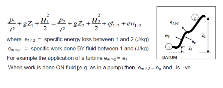
In words, the specific energy entering at 1 is equal to the specific energy at 2, plus any specific energy loss plus any specific work done by fluid.
The above equation is known as the Steady Flow Energy Equation (SFEE). -
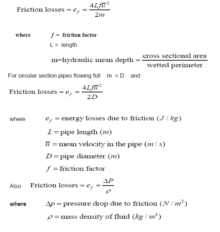
- 6.4 Energy losses
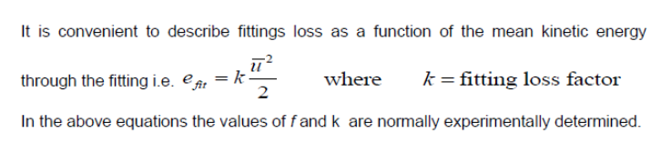
- Energy losses may be conveniently divided into friction loss, along length of pipe or duct and fittings loss, due to changes of geometry(bends etc.) valves, tee junctions etc.
-
- Applications of Steady Flow Energy Equation
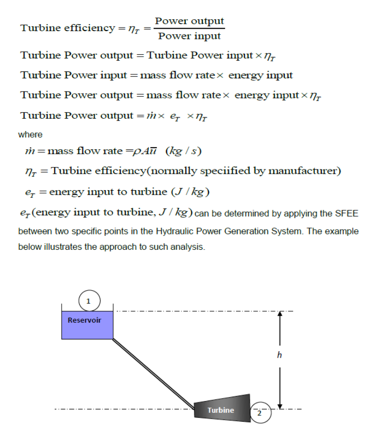
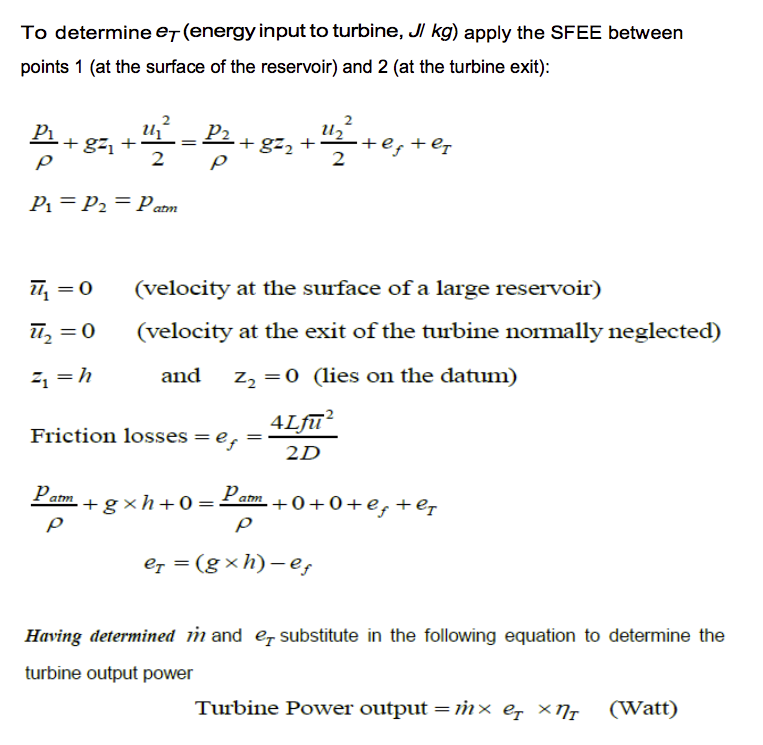
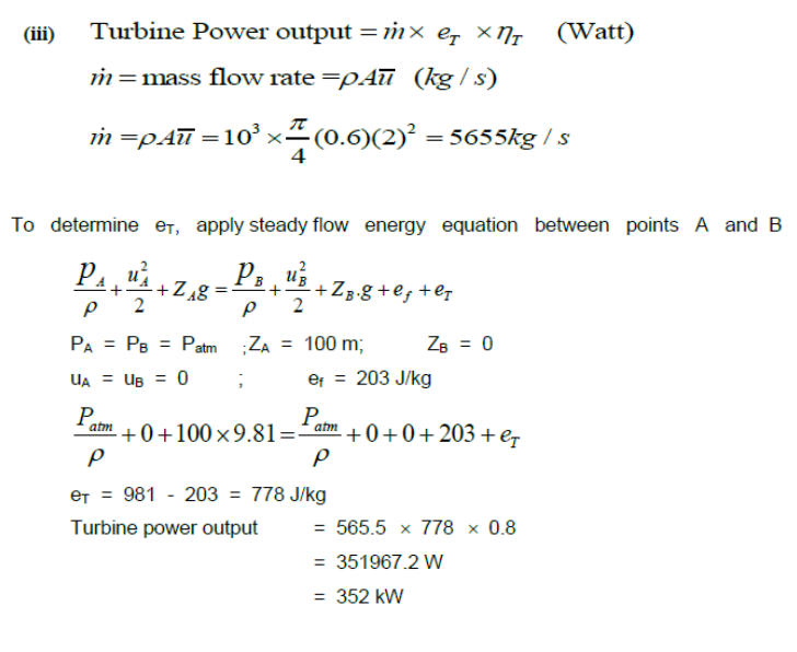
- 6.5.1 Steady incompressible flow system with Hydraulic Turbine
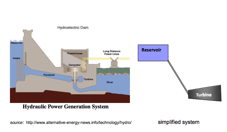
To determine the power output from such arrangements lets start with the turbine efficiency equation:
- Example
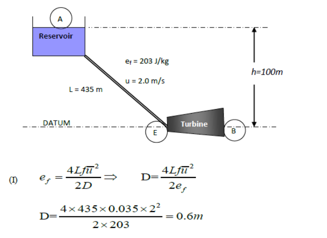
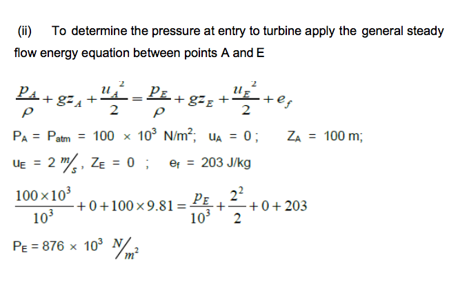
A pipeline of constant diameter and 435 m in length conveys water from a reservoir to a turbine situated 100 m below the reservoir level as shown in the Figure below. The velocity of flow through the pipeline is 2.0 m/s and the energy loss due to friction in the pipeline is 203 J/kg. The water leaves the turbine at atmospheric pressure (100 kN/m2) and with negligible velocity. Assuming an efficiency of 80% for the turbine,determine:
i the pipeline diameter; ii the pressure at entry to the turbine; iii the turbine power output.
Take density of water (p) =103 kg/m3, friction factor (f) = 0.035 and Patm= 100 kN/m2
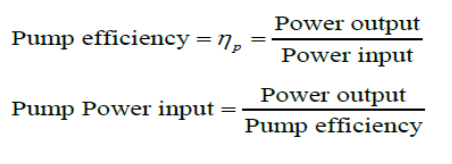
- 6.5.2 Steady incompressible flow system with a pump
To determine the power input to a pump, lets start with the pump efficiency equation:
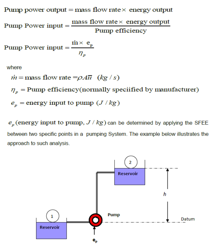
To determine ep (energy input to the pump, J / kg) apply the SFEE between points 1 (at the surface of the lower reservoir) and 2 (at the surface of the upper reservoir)
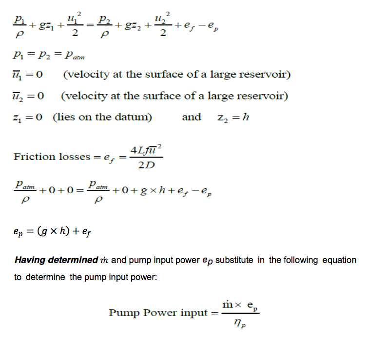
Example
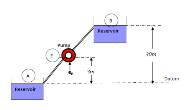
A pump delivers 15 kg/s of water from an open tank to another open tank 30 m above the water level of the first tank as shown in Figure below.
i Given that the friction losses are estimated to be 35 J/kg and the pump has an efficiency of 85%, determine the input power to the pump; ii Determine the pressure at inlet to the pump given that the suction pipe has a diameter of 50 mm and energy losses of 16 J/kg.
Take atmospheric pressure = 100 kN/m2 and density of water = 1000 kg/m3
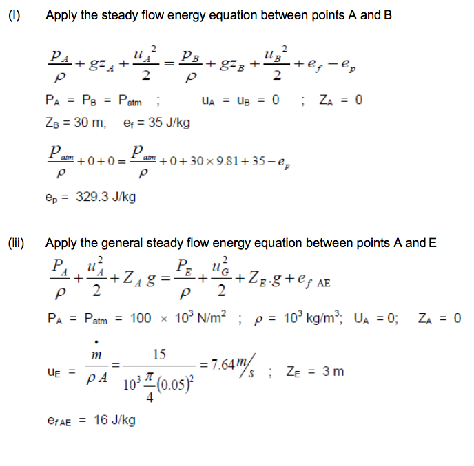
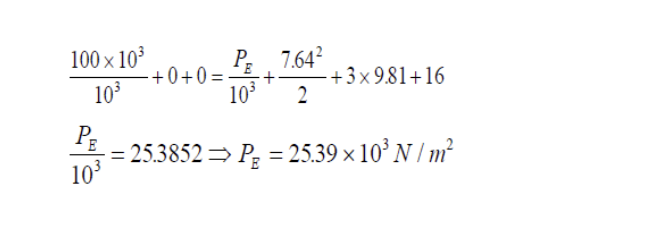
Solution:
Week6 Activities 1-4
4 activity with randomized numbers and tasks using MapleTA
-
- Summary
- This week, we introduced the Steady Flow Energy Equation necessary to analyse fluids in motion, where energy losses are applicable. We described the nature of the energy losses with a special focus on the friction losses. We demonstrated the practical uses of the SFEE in the analysis of turbine systems and pumping systems.
-
-