-
Chapter 3: Objectives
- After completing this chapter, you will be able to:
- Explain how rules are used to facilitate communication.
- Explain the role of protocols and standards organisations in facilitating interoperability in network communications.
- Explain how devices on a LAN access resources in a small to medium-sized business network.
Chapter 3
- Rules of Communication
- Network Protocols and Standards
- Moving Data in the Network
- Summary
-

Establishing the Rules
- Before communicating with one another, individuals must use established rules or agreements to govern the conversation. For example, protocols are necessary for effective communication. These rules, or protocols, must be followed in order for the message to be successfully delivered and understood. Protocols must account for the following requirements:
- An identified sender and receiver
- Common language and grammar
- Speed and timing of delivery
- Confirmation or acknowledgment requirements
- The protocols that are used in network communications share many of these fundamental traits. In addition to identifying the source and destination, computer and network protocols define the details of how a message is transmitted across a network. Common computer protocols include the requirements shown in 📷 this diagram. Each of these will be discussed in more detail.
humans communication between govern rules. It is verydifficult tounderstand messages that are not correctly formatted and donot follow the established rules and protocols. A estrutura da gramatica, da lingua, da pontuacao e do sentance faz a configuracao humana compreensivel por muitos individuos diferentes.Rules govern communication between humans. It is very difficult to understand messages that are not correctly formatted and do not follow the established rules and protocols. The structure of the grammar, the language, the punctuation and the sentence make the configuration humanly understandable for many different individuals.Communication Fundamentals
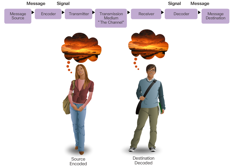
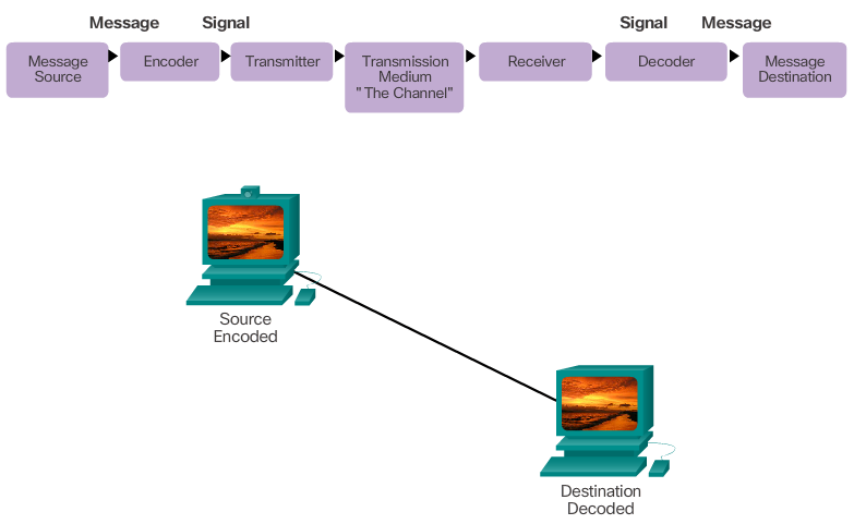
- A network can be as complex as devices connected across the Internet, or as simple as two computers directly connected to one another with a single cable, and anything in-between. Networks can vary in size, shape, and function. However, simply having a wired or wireless physical connection between end devices is not enough to enable communication. For communication to occur, devices must know “how” to communicate. People exchange ideas using many different communication methods. However, regardless of the method chosen, all communication methods have three elements in common. The first of these elements is the message source, or sender. Message sources are people, or electronic devices, that need to send a message to other individuals or devices. The second element of communication is the destination, or receiver, of the message. The destination receives the message and interprets it. A third element, called a channel, consists of the media that provides the pathway over which the message travels from source to destination. Communication begins with a message, or information, that must be sent from a source to a destination. The sending of this message, whether by face-to-face communication or over a network, is governed by rules called protocols. These protocols are specific to the type of communication method occurring. In our day-to-day personal communication, the rules we use to communicate over one medium, like a telephone call, are not necessarily the same as the protocols for using another medium, such as sending a letter. For example, consider two people communicating face-to-face, as shown in 📷 Figure 1. Prior to communicating, they must agree on how to communicate. If the communication is using voice, they must first agree on the language. Next, when they have a message to share, they must be able to format that message in a way that is understandable. For example, if someone uses the English language, but poor sentence structure, the message can easily be misunderstood. Each of these tasks describe protocols put in place to accomplish communication. This is also true of computer communication, as shown in 📷Figure 2. Many different rules or protocols govern all methods of communication that exist in the world today.
X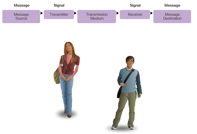 X
X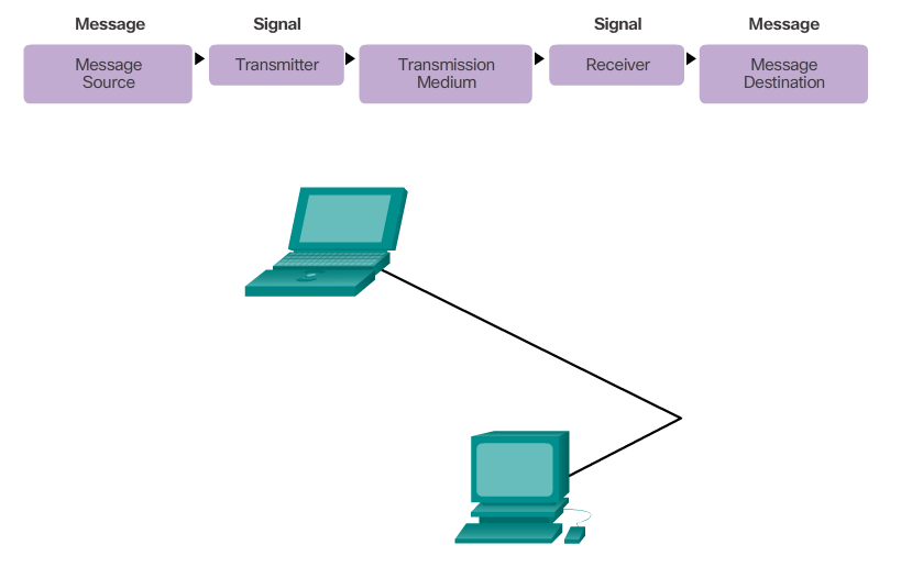 X
X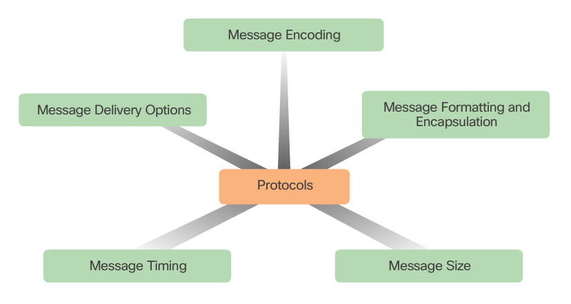
-
Message Formatting and Encapsulation
- When a message is sent from source to destination, it must use a specific format or structure. Message formats depend on the type of message and the channel that is used to deliver the message. Letter writing is one of the most common forms of written human communication. For centuries, the agreed format for personal letters has not changed. In many cultures, a personal letter contains the following elements:
- An identifier of the recipient
- A salutation or greeting
- The message content
- A closing phrase
- An identifier of the sender
- In addition to having the correct format, most personal letters must also be enclosed in an envelope for delivery. The envelope has the address of the sender and receiver, each located at the proper place on the envelope. If the destination address and formatting are not correct, the letter is not delivered. The process of placing one message format (the letter) inside another message format (the envelope) is called encapsulation. De-encapsulation occurs when the process is reversed by the recipient and the letter is removed from the envelope.
- A message that is sent over a computer network follows specific format rules for it to be delivered and processed. Just as a letter is encapsulated in an envelope for delivery, so too are computer messages. Each computer message is encapsulated in a specific format, called a frame, before it is sent over the network. A frame acts like an envelope; it provides the address of the destination and the address of the source host. The distinction between these two types of addresses will be explained later in this chapter.
- The format and contents of a frame are determined by the type of message being sent and the channel over which it is communicated. Messages that are not correctly formatted are not successfully delivered to or processed by the destination host.
Message Encoding
- One of the first steps to sending a message is encoding. Encoding is the process of converting information into another acceptable form, for transmission. Decoding reverses this process in order to interpret the information. Imagine a person planning a holiday trip with a friend, and calling the friend to discuss the details of where they want to go, as shown in Figure 1. To communicate the message, she converts her thoughts into an agreed upon language. She then speaks the words using the sounds and inflections of spoken language that convey the message. Her friend listens to the description and decodes the sounds to understand the message he received. Encoding also occurs in computer communication, as shown in Figure 2. Encoding between hosts must be in an appropriate format for the medium. Messages sent across the network are first converted into bits by the sending host. Each bit is encoded into a pattern of sounds, light waves, or electrical impulses depending on the network media over which the bits are transmitted. The destination host receives and decodes the signals in order to interpret the message.
-
Message Delivery Options
- A message can be delivered in different ways. Sometimes, a person wants to communicate information to a single individual. At other times, the person may need to send information to a group of people at the same time, or even to all people in the same area. There are also times when the sender of a message needs to be sure that the message is delivered successfully to the destination. In these cases, it is necessary for the recipient to return an acknowledgment to the sender. If no acknowledgment is required, the delivery option is referred to as unacknowledged. Hosts on a network use similar delivery options to communicate. A one-to-one delivery option is referred to as a unicast, meaning there is only a single destination for the message. When a host needs to send messages using a one-to-many delivery option, it is referred to as a multicast. Multicasting is the delivery of the same message to a group of host destinations simultaneously. If all hosts on the network need to receive the message at the same time, a broadcast may be used. Broadcasting represents a one-to-all message delivery option. Some protocols use a special multicast message that is sent to all devices, making it essentially the same as a broadcast. Additionally, hosts may be required to acknowledge the receipt of some messages while not needing to acknowledge others.
- Unicast Multicast Broadcast
Message Size
- Another rule of communication is size. When people communicate with each other, the messages that they send are usually broken into smaller parts or sentences. These sentences are limited in size to what the receiving person can process at one time. An individual conversation may be made up of many smaller sentences to ensure that each part of the message is received and understood. Imagine what it would be like to read this course if it all appeared as one long sentence; it would not be easy to read and comprehend. Likewise, when a long message is sent from one host to another over a network, it is necessary to break the message into smaller pieces. The rules that govern the size of the pieces, or frames, communicated across the network are very strict. They can also be different, depending on the channel used. Frames that are too long or too short are not delivered. The size restrictions of frames require the source host to break a long message into individual pieces that meet both the minimum and maximum size requirements. The long message will be sent in separate frames, with each frame containing a piece of the original message. Each frame will also have its own addressing information. At the receiving host, the individual pieces of the message are reconstructed into the original message.
Message Timing
- These are the rules of engagement for message timing.
- Access Method
- Access method determines when someone is able to send a message. If two people talk at the same time, a collision of information occurs and it is necessary for the two to back off and start again. Likewise, it is necessary for computers to define an access method. Hosts on a network need an access method to know when to begin sending messages and how to respond when errors occur.
- Flow Control
- Timing also affects how much information can be sent and the speed that it can be delivered. If one person speaks too quickly, it is difficult for the other person to hear and understand the message. In network communication, source and destination hosts use flow control methods to negotiate correct timing for successful communication.
- Response Timeout
- If a person asks a question and does not hear a response within an acceptable amount of time, the person assumes that no answer is coming and reacts accordingly. The person may repeat the question, or may go on with the conversation. Hosts on the network also have rules that specify how long to wait for responses and what action to take if a response timeout occurs.
-

Rules that Govern Communications
- A group of inter-related protocols necessary to perform a communication function is called a protocol suite. Protocol suites are implemented by hosts and networking devices in software, hardware or both. One of the best ways to visualise how the protocols within a suite interact is to view the interaction as a stack. A protocol stack shows how the individual protocols within a suite are implemented. The protocols are viewed in terms of layers, with each higher level service depending on the functionality defined by the protocols shown in the lower levels. The lower layers of the stack are concerned with moving data over the network and providing services to the upper layers, which are focused on the content of the message being sent. As the 📷 figure shows, we can use layers to describe the activity occurring in our face-to-face communication example. At the bottom, the physical layer, we have two people, each with a voice that can say words out loud. In the middle, the rules layer, we have an agreement to speak in a common language. At the top, the content layer, there are words that are actually spoken. This is the content of the communication.
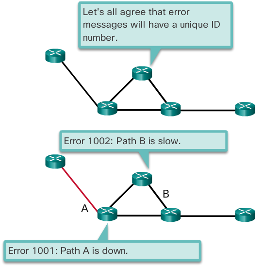
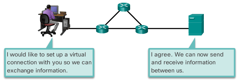
Network Protocols
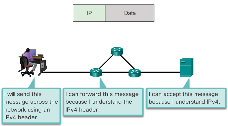
- At the human level, some communication rules are formal and others are simply understood based on custom and practice. For devices to successfully communicate, a network protocol suite must describe precise requirements and interactions. Networking protocols define a common format and set of rules for exchanging messages between devices. Some common networking protocols are Hypertext Transfer Protocol (HTTP), Transmission Control Protocol (TCP), and Internet Protocol (IP). Note: IP in this course refers to both the IPv4 and IPv6 protocols. IPv6 is the most recent version of IP and the replacement for the more common IPv4. The figures illustrate networking protocols that describe the following processes:
- How the message is formatted or structured, as shown in Figure 1
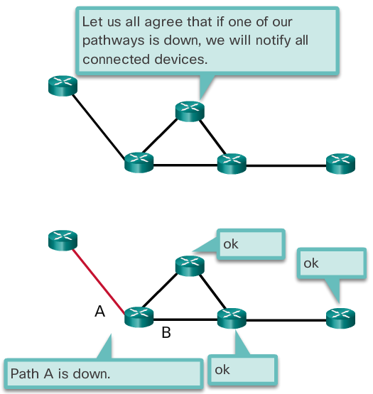
- The process by which networking devices share information about pathways with other networks, as shown in Figure 2
- How and when error and system messages are passed between devices, as shown in Figure 3
- The setup and termination of data transfer sessions, as shown in Figure 4.
X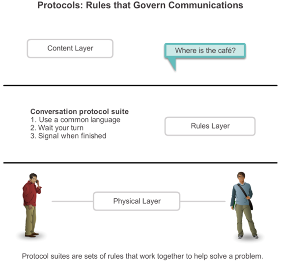
-
Creation of Internet, Development of TCP/IP
- The first packet switching network and predecessor to today’s Internet was the Advanced Research Projects Agency Network (ARPANET), which came to life in 1969 by connecting mainframe computers at four locations. ARPANET was funded by the U.S. Department of Defense for use by universities and research laboratories. Bolt, Beranek and Newman (BBN) was the contractor that did much of the initial development of the ARPANET, including creating the first router known as an Interface Message Processor (IMP). In 1973, Robert Kahn and Vinton Cerf began work on TCP to develop the next generation of the ARPANET. TCP was designed to replace ARPANET’s current Network Control Program (NCP). In 1978, TCP was divided into two protocols: TCP and IP. Later, other protocols were added to the TCP/IP suite of protocols including Telnet, FTP, DNS, and many others.
TCP/IP Protocol Suite
- Today, the TCP/IP protocol suite includes many protocols. The individual protocols are organised in layers using the TCP/IP protocol model: Application, Transport, Internet, and Network Access Layers. TCP/IP protocols are specific to the Application, Transport, and Internet layers. The network access layer protocols are responsible for delivering the IP packet over the physical medium. These lower layer protocols are developed by various standards organisations. The TCP/IP protocol suite is implemented as a TCP/IP stack on both the sending and receiving hosts to provide end-to-end delivery of applications over a network. The Ethernet protocols are used to transmit the IP packet over the physical medium used by the LAN.
Protocol Interaction
- Communication between a web server and web client is an example of an interaction between several protocols. The protocols shown in the figure include:
- HTTP - is an application protocol that governs the way a web server and a web client interact. HTTP defines the content and formatting of the requests and responses that are exchanged between the client and server. Both the client and the web server software implement HTTP as part of the application. HTTP relies on other protocols to govern how the messages are transported between the client and server.
- TCP - is the transport protocol that manages the individual conversations. TCP divides the HTTP messages into smaller pieces, called segments. These segments are sent between the web server and client processes running at the destination host. TCP is also responsible for controlling the size and rate at which messages are exchanged between the server and the client.
- IP - is responsible for taking the formatted segments from TCP, encapsulating them into packets, assigning them the appropriate addresses, and delivering them to the destination host.
- Ethernet - is a network access protocol that describes two primary functions: communication over a data link and the physical transmission of data on the network media. Network access protocols are responsible for taking the packets from IP and formatting them to be transmitted over the media.
Protocol Suites and Industry Standards
- A protocol suite is a set of protocols that work together to provide comprehensive network communication services. A protocol suite may be specified by a standards organisation or developed by a vendor. Protocol suites, like the four shown in the figure, can be a bit overwhelming. However, this course will only cover the protocols of the TCP/IP protocol suite. The TCP/IP protocol suite is an open standard, meaning these protocols are freely available to the public, and any vendor is able to implement these protocols on their hardware or in their software. A standards-based protocol is a process that has been endorsed by the networking industry and approved by a standards organisation. The use of standards in developing and implementing protocols ensures that products from different manufacturers can interoperate successfully. If a protocol is not rigidly observed by a particular manufacturer, their equipment or software may not be able to successfully communicate with products made by other manufacturers. Some protocols are proprietary which means one company or vendor controls the definition of the protocol and how it functions. Examples of proprietary protocols are AppleTalk and Novell Netware, which are legacy protocol suites. It is not uncommon for a vendor (or group of vendors) to develop a proprietary protocol to meet the needs of its customers and later assist in making that proprietary protocol an open standard. For example, click 📹 here to view a video presentation by Bob Metcalfe describing the story of how Ethernet was developed.
X -
Internet Standards cont...
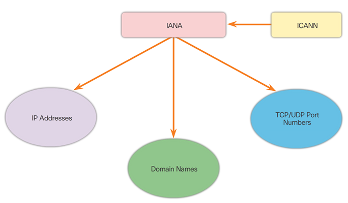
- Standards organisations shown in Figure 2 include:
- Internet Corporation for Assigned Names and Numbers (ICANN) - Based in the United States, coordinates IP address allocation, the management of domain names, and assignment of other information used TCP/IP protocols.
- Internet Assigned Numbers Authority (IANA) - Responsible for overseeing and managing IP address allocation, domain name management, and protocol identifiers for ICANN.
Open Standards
- Open standards encourage interoperability, competition, and innovation. They also guarantee that no single company’s product can monopolise the market, or have an unfair advantage over its competition. A good example of this is when purchasing a wireless router for the home. There are many different choices available from a variety of vendors, all of which incorporate standard protocols such as IPv4, DHCP, 802.3 (Ethernet), and 802.11 (Wireless LAN). These open standards also allow a client running Apple’s OS X operating system to download a web page from a web server running the Linux operating system. This is because both operating systems implement the open standard protocols, such as those in the TCP/IP protocol suite. Standards organisations are important in maintaining an open Internet with freely accessible specifications and protocols that can be implemented by any vendor. A standards organisation may draft a set of rules entirely on its own or in other cases may select a proprietary protocol as the basis for the standard. If a proprietary protocol is used, it usually involves the vendor who created the protocol. Standards organisations are usually vendor-neutral, non-profit organisations established to develop and promote the concept of open standards.
Internet Standards
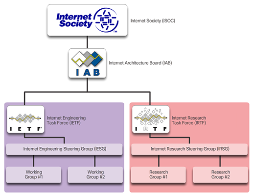
- Standards organisations are usually vendor-neutral, non-profit institutions established to develop and promote the concept of open standards. Various organisations have different responsibilities for promoting and creating standards for the TCP/IP protocol. Standards organisations shown in Figure 1 include:
- Internet Society (ISOC) – Responsible for promoting the open development and evolution of Internet use throughout the world.
- Internet Architecture Board (IAB) - Responsible for the overall management and development of Internet standards.
- Internet Engineering Task Force (IETF) - Develops, updates, and maintains Internet and TCP/IP technologies. This includes the process and documents for developing new protocols and updating existing protocols know as Request for Comments (RFC) documents.
- Internet Research Task Force (IRTF) - Focused on long-term research related to Internet and TCP/IP protocols such as Anti-Spam Research Group (ASRG), Crypto Forum Research Group (CFRG), and Peer-to-Peer Research Group (P2PRG).
-
The Benefits of Using a Layered Model cont...
- As shown in the figure, the TCP/IP model and the Open Systems Interconnection (OSI) model are the primary models used when discussing network functionality. They each represent a basic type of layered networking models:
- Protocol model - This type of model closely matches the structure of a particular protocol suite. The TCP/IP model is a protocol model because it describes the functions that occur at each layer of protocols within the TCP/IP suite. TCP/IP is also used as a reference model.
- Reference model - This type of model provides consistency within all types of network protocols and services by describing what has to be done at a particular layer, but not prescribing how it should be accomplished. The OSI model is a widely known internetwork reference model, but is also a protocol model for the OSI protocol suite.
Electronics and Communications Standard Organisations
- Other standard organizations have responsibilities for promoting and creating the electronic and communication standards used to deliver the IP packets as electronic signals over a wired or wireless medium. Institute of Electrical and Electronics Engineers (IEEE, pronounced “I-triple-E”) – Organization of electrical engineering and electronics dedicated to advancing technological innovation and creating standards in a wide area of industries including power and energy, healthcare, telecommunications, and networking. Electronic Industries Alliance (EIA) - Best known for its standards related to electrical wiring, connectors, and the 19-inch racks used to mount networking equipment. Telecommunications Industry Association (TIA) - Responsible for developing communication standards in a variety of areas including radio equipment, cellular towers, Voice over IP (VoIP) devices, satellite communications, and more. International Telecommunications Union-Telecommunication Standardization Sector (ITU-T) - One of the largest and oldest communication standard organizations. The ITU-T defines standards for video compression, Internet Protocol Television (IPTV), and broadband communications, such as a digital subscriber line (DSL).
The Benefits of Using a Layered Model
- The benefits to using a layered model to describe network protocols and operations include:
- Assisting in protocol design because protocols that operate at a specific layer have defined information that they act upon and a defined interface to the layers above and below.
- Fostering competition because products from different vendors can work together.
- Preventing technology or capability changes in one layer from affecting other layers above and below.
- Providing a common language to describe networking functions and capabilities.
-
The OSI Reference Model
- The OSI model provides an extensive list of functions and services that can occur at each layer. It also describes the interaction of each layer with the layers directly above and below. The TCP/IP protocols discussed in this course are structured around both the OSI and TCP/IP models. Click each layer of the OSI model to view the details. The functionality of each layer and the relationship between layers will become more evident throughout this course as the protocols are discussed in more detail. Note: Whereas the TCP/IP model layers are referred to only by name, the seven OSI model layers are more often referred to by number rather than by name. For instance, the physical layer is referred to as Layer 1 of the OSI model.
Physical The physical layer protocols describe the mechanical, electrical, functional, and procedural means to activate, maintain, and de-activate physical connections for bit transmission to and from a network device.Data Link The data link layer protocols describe methods for exchanging data frames between devices over a common media.Network The network layer provides services to exchange the individual pieces of data over the network between identified end devices.Transport The transport layer defines services to segment, transfer, and reassemble the data for individual communications between the end devices.Session The session layer provides services to the presentation layer to organize its dialogue and to manage data exchange.Presentation The presentation layer provides for common representation of the data transferred between application layer services.Application The application layer contains protocols used for process-to-process communications.
The TCP/IP Protocol Model
- The TCP/IP protocol model for internetwork communications was created in the early 1970s and is sometimes referred to as the Internet model. As shown in the 📷 figure, it defines four categories of functions that must occur for communications to be successful. The architecture of the TCP/IP protocol suite follows the structure of this model. Because of this, the Internet model is commonly referred to as the TCP/IP model. Most protocol models describe a vendor-specific protocol stack. Legacy protocol suites, such as Novell Netware and AppleTalk, are examples of vendor-specific protocol stacks. Because the TCP/IP model is an open standard, one company does not control the definition of the model. The definitions of the standard and the TCP/IP protocols are discussed in a public forum and defined in a publicly available set of RFCs.
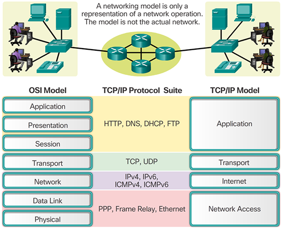
OSI Model and TCP/IP Model Comparison
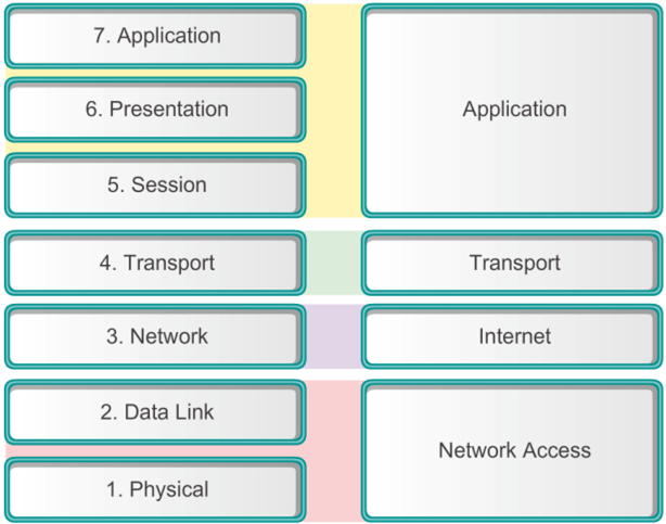
- The protocols that make up the TCP/IP protocol suite can also be described in terms of the OSI reference model. In the OSI model, the network access layer and the application layer of the TCP/IP model are further divided to describe discrete functions that must occur at these layers. At the network access layer, the TCP/IP protocol suite does not specify which protocols to use when transmitting over a physical medium; it only describes the handoff from the internet layer to the physical network protocols. OSI Layers 1 and 2 discuss the necessary procedures to access the media and the physical means to send data over a network. OSI Layer 3, the network layer, maps directly to the TCP/IP Internet layer. This layer is used to describe protocols that address and route messages through an internetwork. OSI Layer 4, the transport layer, maps directly to the TCP/IP Transport layer. This layer describes general services and functions that provide ordered and reliable delivery of data between source and destination hosts. The TCP/IP application layer includes a number of protocols that provide specific functionality to a variety of end user applications. The OSI model Layers 5, 6, and 7 are used as references for application software developers and vendors to produce products that operate on networks. Both the TCP/IP and OSI models are commonly used when referring to protocols at various layers. Because the OSI model separates the data link layer from the physical layer, it is commonly used when referring to these lower layers.
X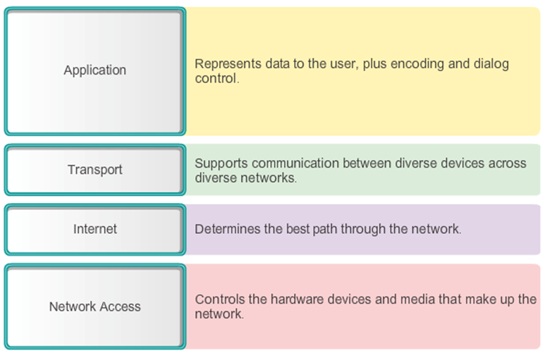
-

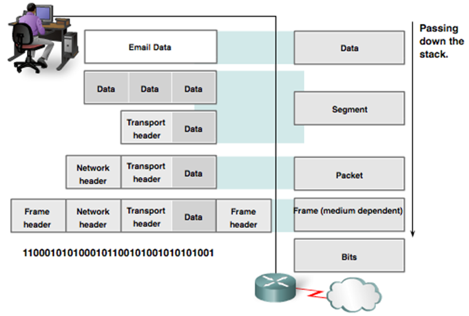
Protocol Data Units
- As application data is passed down the protocol stack on its way to be transmitted across the network media, various protocol information is added at each level. This is known as the encapsulation process. The form that a piece of data takes at any layer is called a protocol data unit (PDU). During encapsulation, each succeeding layer encapsulates the PDU that it receives from the layer above in accordance with the protocol being used. At each stage of the process, a PDU has a different name to reflect its new functions. Although there is no universal naming convention for PDUs, in this course, the PDUs are named according to the protocols of the TCP/IP suite.
Message Segmentation
- In theory, a single communication, such as a music video or an email message, could be sent across a network from a source to a destination as one massive, uninterrupted stream of bits. If messages were actually transmitted in this manner, it would mean that no other device would be able to send or receive messages on the same network while this data transfer was in progress. These large streams of data would result in significant delays. Further, if a link in the interconnected network infrastructure failed during the transmission, the complete message would be lost and have to be retransmitted in full.
- A better approach is to divide the data into smaller, more manageable pieces to send over the network. This division of the data stream into smaller pieces is called segmentation. Segmenting messages has two primary benefits:
- By sending smaller individual pieces from source to destination, many different conversations can be interleaved on the network, called multiplexing.
- Segmentation can increase the efficiency of network communications. If part of the message fails to make it to the destination, due to failure in the network or network congestion, only the missing parts need to be retransmitted.
- The challenge to using segmentation and multiplexing to transmit messages across a network is the level of complexity that is added to the process. Imagine if you had to send a 100-page letter, but each envelope would only hold one page. The process of addressing, labeling, sending, receiving, and opening the entire 100 envelopes would be time-consuming for both the sender and the recipient.
- In network communications, each segment of the message must go through a similar process to ensure that it gets to the correct destination and can be reassembled into the content of the original message.
- 📷 View Diagram
X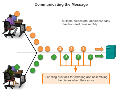
-
Network Addresses cont...
Encapsulation Example
- When sending messages on a network, the encapsulation process works from top to bottom. At each layer, the upper layer information is considered data within the encapsulated protocol. For example, the TCP segment is considered data within the IP packet.
- 📷 View Diagram
De-encapsulation
- This process is reversed at the receiving host, and is known as de-encapsulation. De-encapsulation is the process used by a receiving device to remove one or more of the protocol headers. The data is de-encapsulated as it moves up the stack toward the end-user application.
- 📷 View Diagram
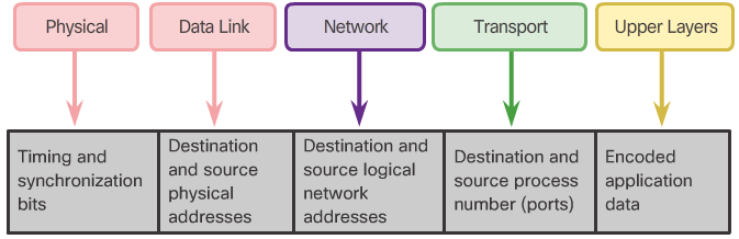
Network Addresses
- The network and data link layers are responsible for delivering the data from the source device to the destination device. As shown in Figure 1, protocols at both layers contain a source and destination address, but their addresses have different purposes.
- Network layer source and destination addresses - Responsible for delivering the IP packet from the original source to the final destination, either on the same network or to a remote network.
- Data link layer source and destination addresses – Responsible for delivering the data link frame from one network interface card (NIC) to another NIC on the same network.
- An IP address is the network layer, or Layer 3, logical address used to deliver the IP packet from the original source to the final destination, as shown in Figure 2.
- The IP packet contains two IP addresses:
- Source IP address - The IP address of the sending device, the original source of the packet.
- Destination IP address - The IP address of the receiving device, the final destination of the packet.
X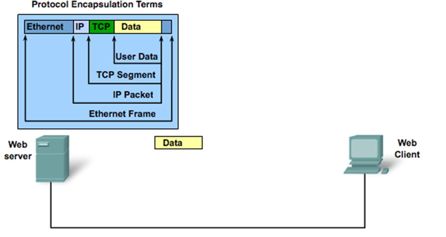 X
X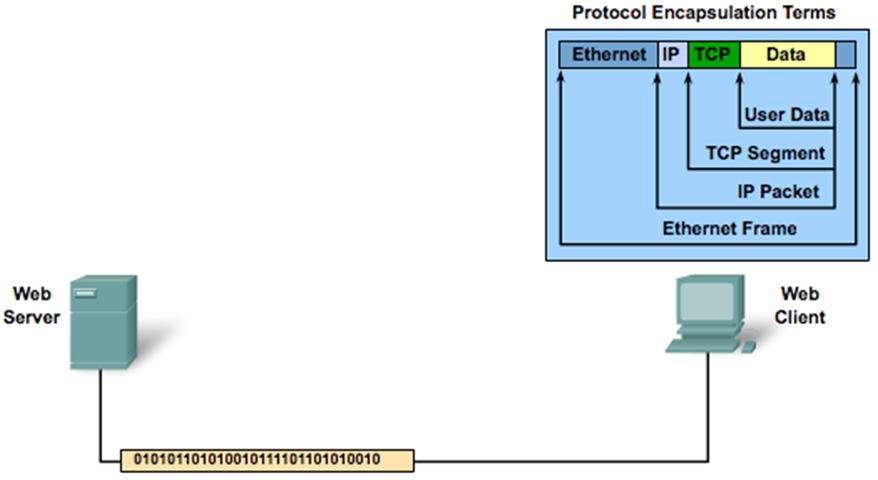
-
Data Link Addresses
- The data link, or Layer 2, physical address has a different role. The purpose of the data link address is to deliver the data link frame from one network interface to another network interface on the same network. This process is illustrated in Figures 1 through 3. Before an IP packet can be sent over a wired or wireless network, it must be encapsulated in a data link frame so it can be transmitted over the physical medium. As the IP packet travels from host-to-router, router-to-router, and finally router-to-host, at each point along the way the IP packet is encapsulated in a new data link frame. Each data link frame contains the source data link address of the NIC card sending the frame, and the destination data link address of the NIC card receiving the frame. The Layer 2, data link protocol is only used to deliver the packet from NIC-to-NIC on the same network. The router removes the Layer 2 information as it is received on one NIC and adds new data link information before forwarding out the exit NIC on its way towards the final destination. The IP packet is encapsulated in a data link frame that contains data link information, including a:
- Source data link address - The physical address of the device’s NIC that is sending the data link frame.
- Destination data link address - The physical address of the NIC that is receiving the data link frame. This address is either the next hop router or of the final destination device.
- The data link frame also contains a trailer which will be discussed in later chapters.
-
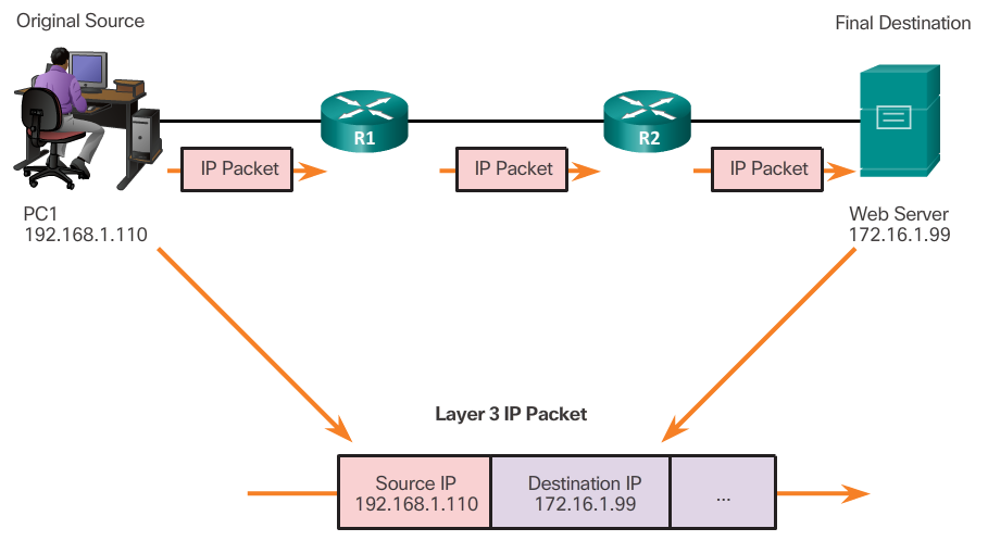
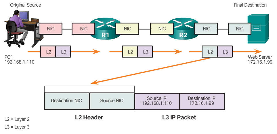
Devices on a Remote Network
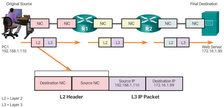
- But what are the roles of the network layer address and the data link layer address when a device is communicating with a device on a remote network? In this example we have a client computer, PC1, communicating with a server, named Web Server, on a different IP network.
- Role of the Network Layer Addresses
- When the sender of the packet is on a different network from the receiver, the source and destination IP addresses will represent hosts on different networks. This will be indicated by the network portion of the IP address of the destination host.
- Source IP address - The IP address of the sending device, the client computer PC1: 192.168.1.110.
- Destination IP address - The IP address of the receiving device, the server, Web Server: 172.16.1.99.
- Notice in the 📷 figure that the network portion of the source IP address and destination IP address are on different networks.
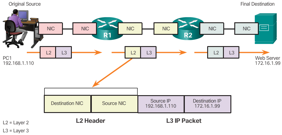
- Role of the Data Link Layer Addresses
- When the sender and receiver of the IP packet are on different networks, the Ethernet data link frame cannot be sent directly to the destination host because the host is not directly reachable in the network of the sender. The Ethernet frame must be sent to another device known as the router or default gateway. In our example, the default gateway is R1. R1 has an Ethernet data link address that is on the same network as PC1. This allows PC1 to reach the router directly.
- Source MAC address - The Ethernet MAC address of the sending device, PC1. The MAC address of the Ethernet interface of PC1 is AA-AA-AA-AA-AA-AA.
- Destination MAC address - When the receiving device, the destination IP address, is on a different network from the sending device, the sending device uses the Ethernet MAC address of the default gateway or router. In this example, the destination MAC address is the MAC address of R1's Ethernet interface, 11-11-11-11-11-11. This is the interface that is attached to the same network as PC1.
- The Ethernet frame with the encapsulated IP packet can now be transmitted to R1. R1 forwards the packet to the destination, Web Server. This may mean that R1 forwards the packet to another router or directly to Web Server if the destination is on a network connected to R1.
- It is important that the IP address of the default gateway be configured on each host on the local network. All packets to a destination on remote networks are sent to the default gateway. Ethernet MAC addresses and the default gateway are discussed in later chapters.
Devices on the Same Network
- To understand how devices communicate within a network, it is important to understand the roles of both the network layer addresses and the data link addresses.
- Role of the Network Layer Addresses
- The network layer addresses, or IP addresses, indicate the original source and final destination. An IP address contains two parts:
- Network portion – The left-most part of the address that indicates which network the IP address is a member. All devices on the same network will have the same network portion of the address.
- Host portion – The remaining part of the address that identifies a specific device on the network. The host portion is unique for each device on the network.
- Note: The subnet mask is used to identify the network portion of an address from the host portion. The subnet mask is discussed in later chapters.
- In this example we have a client computer, PC1, communicating with an FTP server on the same IP network.
- Source IP address - The IP address of the sending device, the client computer PC1: 192.168.1.110.
- Destination IP address - The IP address of the receiving device, FTP server: 192.168.1.9.
- Notice in the 📷 figure that the network portion of both the source IP address and destination IP address are on the same network.
- Role of the Data Link Layer Addresses
- When the sender and receiver of the IP packet are on the same network, the data link frame is sent directly to the receiving device. On an Ethernet network, the data link addresses are known as Ethernet (Media Access Control) addresses. MAC addresses are physically embedded on the Ethernet NIC.
- Source MAC address - This is the data link address, or the Ethernet MAC address, of the device that sends the data link frame with the encapsulated IP packet. The MAC address of the Ethernet NIC of PC1 is AA-AA-AA-AA-AA-AA, written in hexadecimal notation.
- Destination MAC address - When the receiving device is on the same network as the sending device, this is the data link address of the receiving device. In this example, the destination MAC address is the MAC address of the FTP server: CC-CC-CC-CC-CC-CC, written in hexadecimal notation.
- The frame with the encapsulated IP packet can now be transmitted from PC1 directly to the FTP server.
X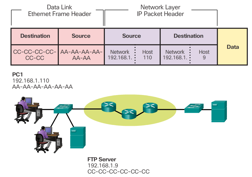 X
X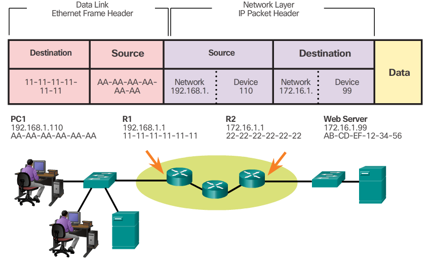
-
Summary
- In this chapter, you learned:
- Data networks are systems of end devices, intermediary devices, and the media connecting the devices. For communication to occur, these devices must know how to communicate.
- These devices must comply with communication rules and protocols. TCP/IP is an example of a protocol suite.
- Most protocols are created by a standards organisation such as the IETF or IEEE.
- The most widely-used networking models are the OSI and TCP/IP models.
- Data that passes down the stack of the OSI model is segmented into pieces and encapsulated with addresses and other labels. The process is reversed as the pieces are de-encapsulated and passed up the destination protocol stack.
- The OSI model describes the processes of encoding, formatting, segmenting, and encapsulating data for transmission over the network.
- The TCP/IP protocol suite is an open standard protocol that has been endorsed by the networking industry and ratified, or approved, by a standards organisation.
- The Internet Protocol Suite is a suite of protocols required for transmitting and receiving information using the Internet.
- Protocol Data Units (PDUs) are named according to the protocols of the TCP/IP suite: data, segment, packet, frame, and bits.
- Applying models allows individuals, companies, and trade associations to analyse current networks and plan the networks of the future.