05
-

Chapter 5: Objectives
- Upon completion of this chapter, you will be able to:
- Describe the operation of the Ethernet sublayers.
- Identify the major fields of the Ethernet frame.
- Describe the purpose and characteristics of the Ethernet MAC address.
- Describe the purpose of ARP.
- Explain how ARP requests impact network and host performance.
- Explain basic switching concepts.
- Compare fixed configuration and modular switches.
- Configure a Layer 3 switch.
Chapter 5
- Ethernet Protocol
- Address Resolution Protocol
- LAN Switches
- Summary
-

Ethernet Encapsulation
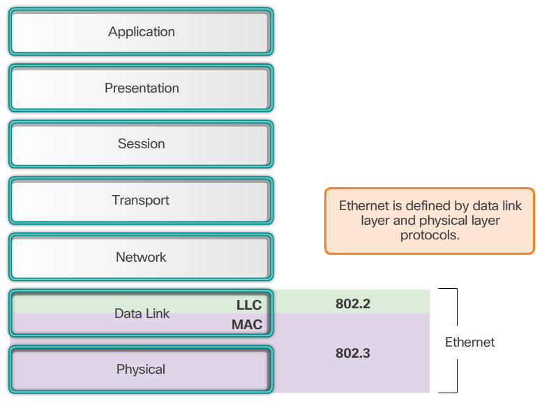
- Ethernet is the most widely used LAN technology today. Ethernet operates in the data link layer and the physical layer. It is a family of networking technologies that are defined in the IEEE 802.2 and 802.3 standards. Ethernet supports data bandwidths of:
- 10 Mb/s
- 100 Mb/s
- 1000 Mb/s (1 Gb/s)
- 10,000 Mb/s (10 Gb/s)
- 40,000 Mb/s (40 Gb/s)
- 100,000 Mb/s (100 Gb/s)
- As shown in Figure 1, Ethernet standards define both the Layer 2 protocols and the Layer 1 technologies. For the Layer 2 protocols, as with all 802 IEEE standards, Ethernet relies on the two separate sublayers of the data link layer to operate, the Logical Link Control (LLC) and the MAC sublayers.
- LLC sublayer
- The Ethernet LLC sublayer handles the communication between the upper layers and the lower layers. This is typically between the networking software and the device hardware. The LLC sublayer takes the network protocol data, which is typically an IPv4 packet, and adds control information to help deliver the packet to the destination node. The LLC is used to communicate with the upper layers of the application, and transition the packet to the lower layers for delivery. LLC is implemented in software, and its implementation is independent of the hardware. In a computer, the LLC can be considered the driver software for the NIC. The NIC driver is a program that interacts directly with the hardware on the NIC to pass the data between the MAC sublayer and the physical media.
- MAC sublayer
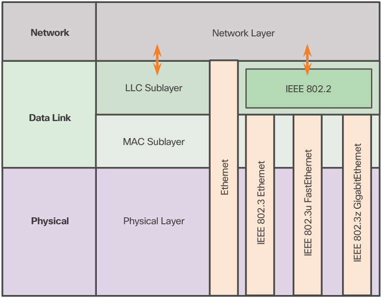
- MAC constitutes the lower sublayer of the data link layer. MAC is implemented by hardware, typically in the computer NIC. The specifics are listed in the IEEE 802.3 standards. Figure 2 lists common IEEE Ethernet standards.
-
Media Access Control
- Carrier Sense Multiple Access (CSMA) process
- Used to first detect if the media is carrying a signal
- If no carrier signal is detected, the device transmits its data
- If two devices transmit at the same time - data collision
- 📷 View Diagram
- CSMA is usually implemented in conjunction with a method for resolving media contention. The two commonly used methods are: CSMA/Collision Detection and CSMA/Collision Avoidance CSMA/Collision Detection
- The device monitors the media for the presence of a data signal
- If a data signal is absent, indicating that the media is free, the device transmits the data
- If signals are then detected that show another device was transmitting at the same time, all devices stop sending & try again later
- While Ethernet networks are designed with CSMA/CD technology, with today’s intermediate devices, collisions do not occur and the processes utilized by CSMA/CD are really unnecessary
- Wireless connections in a LAN environment still have to take collisions into account
- CSMA/Collision Avoidance (CSMA/CA) media access method
- Device examines the media for the presence of data signal - if the media is free, the device sends a notification across the media of its intent to use it
- The device then sends the data.
- Used by 802.11 wireless networking technologies
MAC Sublayer
- As shown in the 📷 figure, the Ethernet MAC sublayer has two primary responsibilities:
- Data encapsulation
- Media access control
- Data encapsulation
- The data encapsulation process includes frame assembly before transmission, and frame disassembly upon reception of a frame. In forming the frame, the MAC layer adds a header and trailer to the network layer PDU. Data encapsulation provides three primary functions:
- Frame delimiting - The framing process provides important delimiters that are used to identify a group of bits that make up a frame. These delimiting bits provide synchronization between the transmitting and receiving nodes.
- Addressing - The encapsulation process contains the Layer 3 PDU and also provides for data link layer addressing.
- Error detection - Each frame contains a trailer used to detect any errors in transmissions.
- The use of frames aids in the transmission of bits as they are placed on the media and in the grouping of bits at the receiving node.
- Media Access Control
- The second responsibility of the MAC sublayer is media access control. Media access control is responsible for the placement of frames on the media and the removal of frames from the media. As its name implies, it controls access to the media. This sublayer communicates directly with the physical layer. The underlying logical topology of Ethernet is a multi-access bus; therefore, all nodes (devices) on a single network segment share the medium. Ethernet is a contention-based method of networking. A contention-based method means that any device can try to transmit data across the shared medium whenever it has data to send. The Carrier Sense Multiple Access/Collision Detection (CSMA/CD) process is used in half-duplex Ethernet LANs to detect and resolve collisions. Today’s Ethernet LANs use full-duplex switches, which allow multiple devices to send and receive simultaneously with no collisions.
X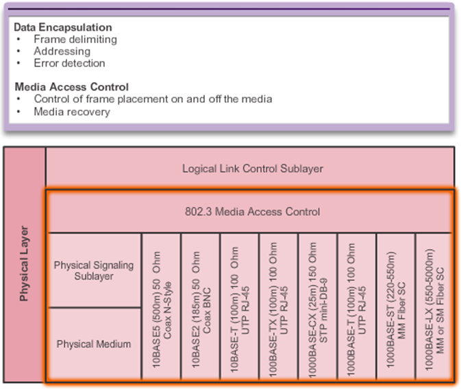 X
X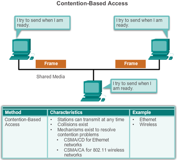
-
Frame Processing cont...
- When a NIC receives an Ethernet frame, it examines the destination MAC address to see if it matches the device’s physical MAC address stored in RAM. If there is no match, the device discards the frame. If there is a match, it passes the frame up the OSI layers, where the de-encapsulation process takes place. Note: Ethernet NICs will also accept frames if the destination MAC address is a broadcast or a multicast group of which the host is a member. Any device that can be the source or destination of an Ethernet frame must be assigned a MAC address. This includes workstations, servers, printers, mobile devices, and routers.
Ethernet Encapsulation
- Early versions of Ethernet were slow at 10 Mb/s.
- Now operate at 10 Gb/s per second and faster.
- Ethernet frame structure adds headers and trailers around the Layer 3 PDU to encapsulate the message being sent.
- 📷 Ethernet II is the Ethernet frame format used in TCP/IP networks.
Ethernet Frame Size
- Ethernet II and IEEE 802.3 standards define the minimum frame size as 64 bytes and the maximum as 1518 bytes
- Less than 64 bytes in length is considered a "collision fragment" or "runt frame”
- If size of a transmitted frame is less than the minimum or greater than the maximum, the receiving device drops the frame
- At the physical layer, different versions of Ethernet vary in their method for detecting and placing data on the media
- 📷 View Diagram
MAC Address: Ethernet Identity
- In Ethernet, every network device is connected to the same, shared media. Ethernet was once predominantly a half-duplex topology using a multi-access bus or later Ethernet hubs. This meant that all nodes would receive every frame transmitted. To prevent the excessive overhead involved in the processing of every frame, MAC addresses were created to identify the actual source and destination. MAC addressing provides a method for device identification at the lower level of the OSI model. Although Ethernet has now transitioned to full-duplex NICs and switches, it is still possible that a device that is not the intended destination will receive an Ethernet frame.
- MAC Address Structure
- The MAC address value is a direct result of IEEE-enforced rules for vendors to ensure globally unique addresses for each Ethernet device. The rules established by IEEE require any vendor that sells Ethernet devices to register with IEEE. The IEEE assigns the vendor a 3-byte (24-bit) code, called the Organizationally Unique Identifier (OUI). IEEE requires a vendor to follow two simple rules, as shown in the 📷 figure:
- All MAC addresses assigned to a NIC or other Ethernet device must use that vendor's assigned OUI as the first 3 bytes.
- All MAC addresses with the same OUI must be assigned a unique value in the last 3 bytes.
- Note: It is possible for duplicate MAC addresses to exist due to mistakes during manufacturing or in some virtual machine implementation methods. In either case, it will be necessary to modify the MAC address with a new NIC or in software.
Frame Processing
- The MAC address is often referred to as a burned-in address (BIA) because, historically, this address is burned into ROM (Read-Only Memory) on the NIC. This means that the address is encoded into the ROM chip permanently. Note: On modern PC operating systems and NICs, it is possible to change the MAC address in software. This is useful when attempting to gain access to a network that filters based on BIA. Consequently, filtering or controlling traffic based on the MAC address is no longer as secure. When the computer starts up, the first thing the NIC does is copy the MAC address from ROM into RAM. When a device is forwarding a message to an Ethernet network, it attaches header information to the packet. The header information contains the source and destination MAC address.
X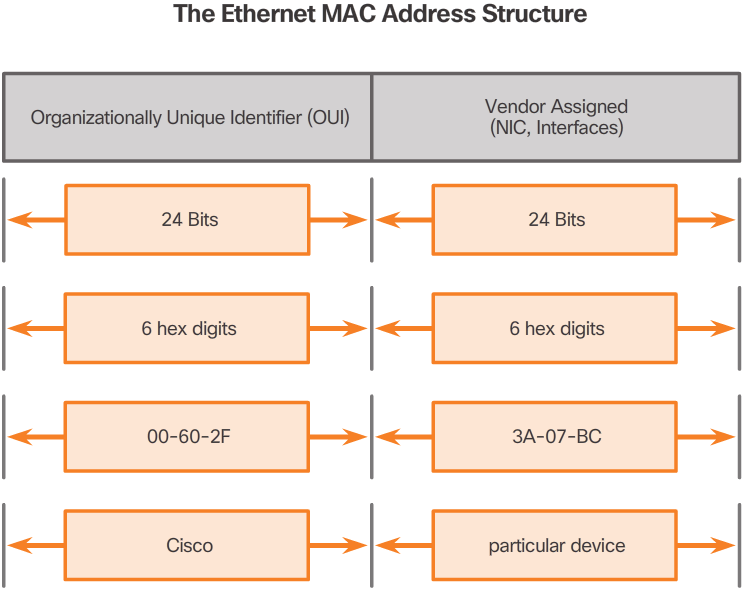 X
X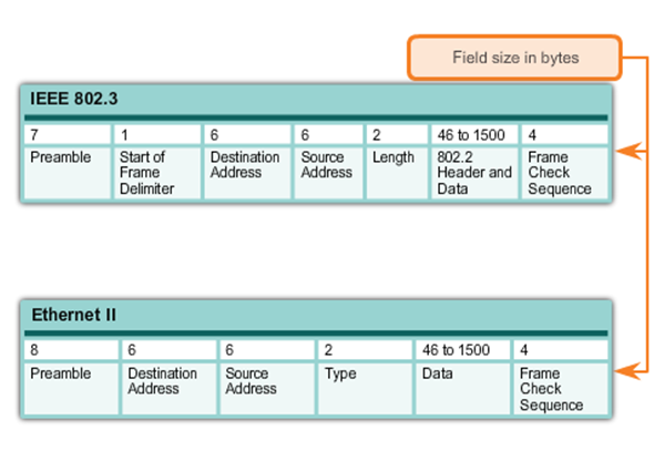 X
X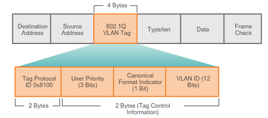
- The figure displays the fields contained in the 802.1Q VLAN tag
-
MAC Address and Hexadecimal
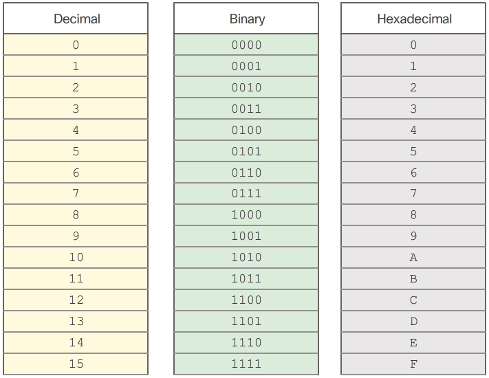
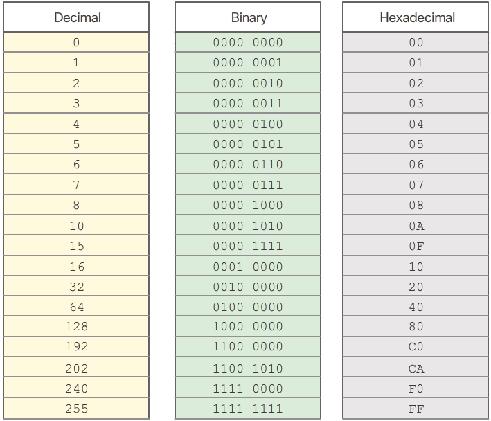
- An Ethernet MAC address is a 48-bit binary value expressed as 12 hexadecimal digits (4 bits per hexadecimal digit). Just as decimal is a base ten number system, hexadecimal is a base sixteen system. The base sixteen number system uses the numbers 0 to 9 and the letters A to F. Figure 1 shows the equivalent decimal and hexadecimal values for binary 0000 to 1111. It is easier to express a value as a single hexadecimal digit than as four binary bits. Given that 8 bits (one byte) is a common binary grouping, binary 00000000 to 11111111 can be represented in hexadecimal as the range 00 to FF, as shown in Figure 2. Leading zeroes are always displayed to complete the 8-bit representation. For example, the binary value 0000 1010 is shown in hexadecimal as 0A. Note: It is important to distinguish hexadecimal values from decimal values regarding the characters 0 to 9, as shown in the figure. Representing Hexadecimal Values Hexadecimal is usually represented in text by the value preceded by 0x (for example 0x73) or a subscript 16. Less commonly, it may be followed by an H(for example 73H). However, because subscript text is not recognized in command line or programming environments, the technical representation of hexadecimal is preceded with "0x" (zero X). Therefore, the examples above would be shown as 0x0A and 0x73 respectively. Hexadecimal is used to represent Ethernet MAC addresses and IP Version 6 addresses. Hexadecimal Conversions Number conversions between decimal and hexadecimal values are straightforward, but quickly dividing or multiplying by 16 is not always convenient. If such conversions are required, it is usually easier to convert the decimal or hexadecimal value to binary, and then to convert the binary value to either decimal or hexadecimal as appropriate.
-
Unicast MAC Address
- In Ethernet, different MAC addresses are used for Layer 2 unicast, broadcast, and multicast communications. A unicast MAC address is the unique address used when a frame is sent from a single transmitting device to a single destination device. In the example shown in the 📷 diagram, a host with IPv4 address 192.168.1.5 (source) requests a web page from the server at IPv4 unicast address 192.168.1.200. For a unicast packet to be sent and received, a destination IP address must be in the IP packet header. A corresponding destination MAC address must also be present in the Ethernet frame header. The IP address and MAC address combine to deliver data to one specific destination host. The process that a source host uses to determine the destination MAC address is known as Address Resolution Protocol (ARP). ARP is discussed later in this chapter. Although the destination MAC address can be a unicast, broadcast, or multicast address, the source MAC address must always be a unicast.
Broadcast MAC Address
- A broadcast packet contains a destination IPv4 address that has all ones (1s) in the host portion. This numbering in the address means that all hosts on that local network (broadcast domain) will receive and process the packet. Many network protocols, such as DHCP and ARP, use broadcasts. As shown in the 📷 diagram, the source host sends an IPv4 broadcast packet to all devices on its network. The IPv4 destination address is a broadcast address, 192.168.1.255. When the IPv4 broadcast packet is encapsulated in the Ethernet frame, the destination MAC address is the broadcast MAC address of FF-FF-FF-FF-FF-FF in hexadecimal (48 ones in binary).
MAC Address Representations
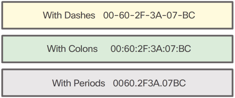
- Different hardware and software manufacturers might represent the MAC address in different hexadecimal formats, as shown in the following:
- 00-05-9A-3C-78-00
- 00:05:9A:3C:78:00
- 0005.9A3C.7800
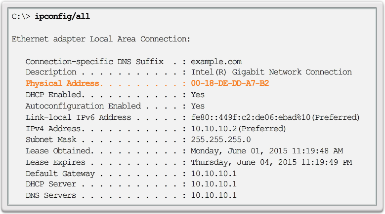
- On a Windows host, the ipconfig /all command can be used to identify the MAC address of an Ethernet adapter. In Figure 1, notice the display indicates the Physical Address (MAC) of the computer to be 00-18-DE-DD-A7-B2. If you have access, you may wish to try this on your own computer. On a MAC or Linux host, the ifconfig command is used. Depending on the device and the operating system, you will see various representations of MAC addresses, as displayed in Figure 2. Cisco routers and switches use the form XXXX.XXXX.XXXX where X is a hexadecimal character.
X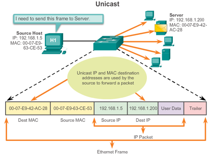 X
X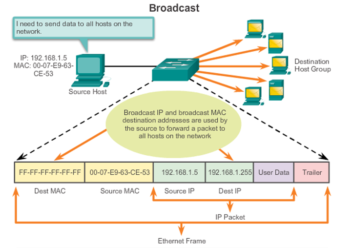
-
End-to-End Connectivity, MAC, and IP
Destination MAC
Address
BB:BB:BB:BB:BB:BBSource MAC Address
AA:AA:AA:AA:AA:AASource IP
Address
10.0.0.1Destination
IP Address
192.168.1.5Data Trailer - A Switch examines MAC addresses.
Destination MAC
Address
BB:BB:BB:BB:BB:BBSource MAC Address
AA:AA:AA:AA:AA:AASource IP
Address
10.0.0.1Destination
IP Address
192.168.1.5Data Trailer - A router examines IP addresses
- 📷 The Data Link Layer
Multicast MAC Address
- Multicast addresses allow a source device to send a packet to a group of devices. Devices that belong to a multicast group are assigned a multicast group IP address. The range of IPv4 multicast addresses is 224.0.0.0 to 239.255.255.255. Because multicast addresses represent a group of addresses (sometimes called a host group), they can only be used as the destination of a packet. The source will always be a unicast address. Multicast addresses would be used in remote gaming, where many players are connected remotely but playing the same game. Another use of multicast addresses is in distance learning through video conferencing, where many students are connected to the same class. As with the unicast and broadcast addresses, the multicast IP address requires a corresponding multicast MAC address to actually deliver frames on a local network. The multicast MAC address is a special value that begins with 01-00-5E in hexadecimal. The remaining portion of the multicast MAC address is created by converting the lower 23 bits of the IP multicast group address into 6 hexadecimal characters. An example, as shown in the 📷 diagram, is the multicast hexadecimal address 01-00-5E-00-00-C8. The last byte, or eight bits, of the IP address 224.0.0.200, is the decimal value 200. The easiest way to see the hexadecimal equivalent is to first convert it to binary with a space between each four bits, 200 (decimal) = 1100 1000 (binary). Using the binary to hexadecimal conversion chart shown earlier, 1100 1000 (binary) = 0xC8.
MAC and IP
- MAC Address
- This address does not change
- Similar to the name of a person
- Known as physical address because physically assigned to the host NIC
- IP Address
- Similar to the address of a person
- Based on where the host is actually located
- Known as a logical address because assigned logically
- Assigned to each host by a network administrator
- Both the physical MAC and logical IP addresses are required for a computer to communicate just like both the name and address of a person are required to send a letter.
X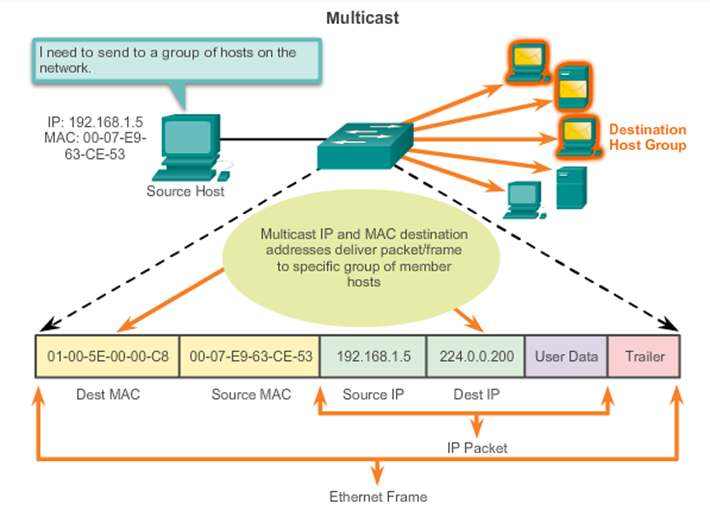 X
X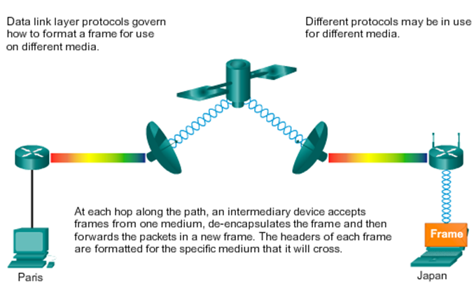
-

ARP Role in Remote Communication
- If the destination IPv4 host is on the local network, the frame will use the MAC address of this device as the destination MAC address. If the destination IPv4 host is not on the local network, the source uses the ARP process to determine a MAC address for the router interface serving as the gateway. In the event that the gateway entry is not in the table, an ARP request is used to retrieve the MAC address associated with the IP address of the router interface.
Removing Entries from an ARP Table
- For each device, an ARP cache timer removes ARP entries that have not been used for a specified period of time. The times differ depending on the device’s operating system. For example, some Windows operating systems store ARP cache entries for 2 minutes, as shown in the 📷 figure. Commands may also be used to manually remove all or some of the entries in the ARP table. After an entry has been removed, the process for sending an ARP request and receiving an ARP reply must occur again to enter the map in the ARP table.
Introduction to ARP
- Recall that every device with an IP address on an Ethernet network also has an Ethernet MAC address. When a device sends an Ethernet frame, it contains these two addresses:
- Destination MAC address - The MAC address of the Ethernet NIC, which will be either the MAC address of the final destination device or the router.
- Source MAC address - The MAC address of the sender’s Ethernet NIC.
- To determine the destination MAC address, the device uses ARP. ARP provides two basic functions:
- Resolving IPv4 addresses to MAC addresses
- Maintaining a table of mappings
ARP Functions
- Resolving IPv4 Addresses to MAC Addresses
- When a packet is sent to the data link layer to be encapsulated into an Ethernet frame, the device refers to a table in its memory to find the MAC address that is mapped to the IPv4 address. This table is called the ARP table or the ARP cache. The ARP table is stored in the RAM of the device. The sending device will search its ARP table for a destination IPv4 address and a corresponding MAC address.
- If the packet’s destination IPv4 address is on the same network as the source IPv4 address, the device will search the ARP table for the destination IPv4 address.
- If the destination IPv4 address is on a different network than the source IPv4 address, the device will search the ARP table for the IPv4 address of the default gateway.
- In both cases, the search is for an IPv4 address and a corresponding MAC address for the device. Each entry, or row, of the ARP table binds an IPv4 address with a MAC address. We call the relationship between the two values a map - it simply means that you can locate an IPv4 address in the table and discover the corresponding MAC address. The ARP table temporarily saves (caches) the mapping for the devices on the LAN. If the device locates the IPv4 address, its corresponding MAC address is used as the destination MAC address in the frame. If there is no entry is found, then the device sends an ARP request.
X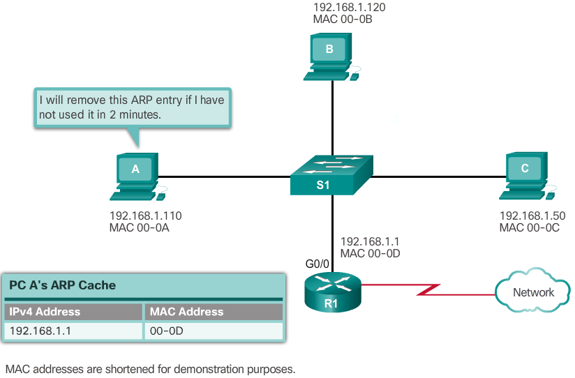
-
ARP Spoofing
- In some cases, the use of ARP can lead to a potential security risk known as ARP spoofing or ARP poisoning. This is a technique used by an attacker to reply to an ARP request for an IPv4 address belonging to another device, such as the default gateway, as shown in the 📷 figure. The attacker sends an ARP reply with its own MAC address. The receiver of the ARP reply will add the wrong MAC address to its ARP table and send these packets to the attacker.
- Enterprise level switches include mitigation techniques known as dynamic ARP inspection (DAI). DAI is beyond the scope of this course.
- 📷 Mitigating ARP Problems
ARP Tables
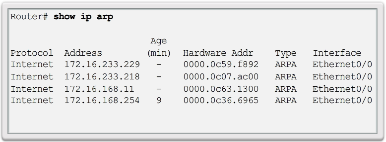
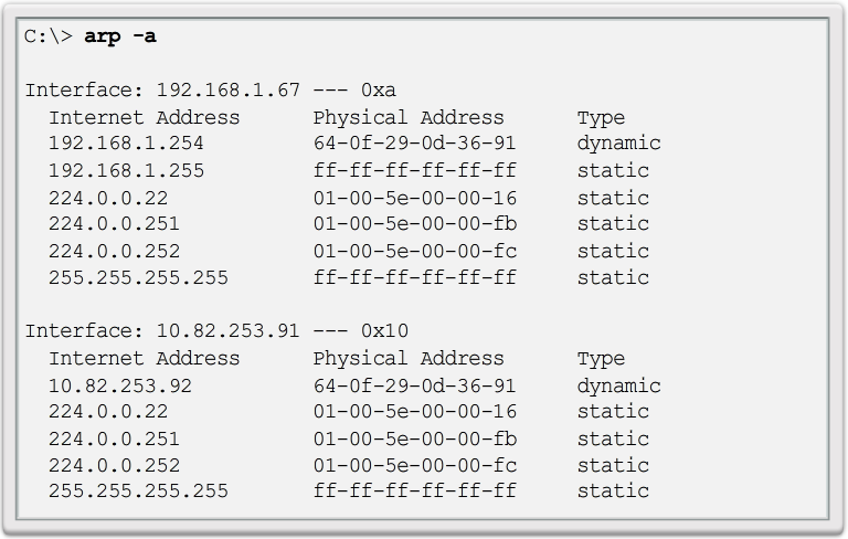
- On a Cisco router, the show ip arp command is used to display the ARP table, as shown in Figure 1. On a Windows 7 PC, the arp –a command is used to display the ARP table, as shown in Figure 2.
ARP Broadcasts
- As a broadcast frame, an ARP request is received and processed by every device on the local network. On a typical business network, these broadcasts would probably have minimal impact on network performance. However, if a large number of devices were to be powered up and all start accessing network services at the same time, there could be some reduction in performance for a short period of time, as shown in the 📷 figure. After the devices send out the initial ARP broadcasts and have learned the necessary MAC addresses, any impact on the network will be minimized.
X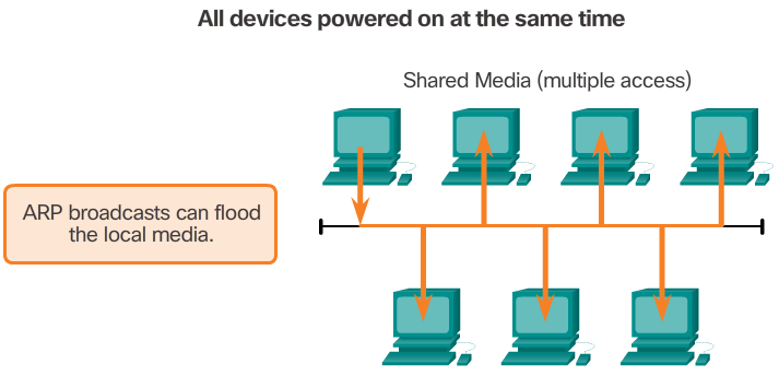 X
X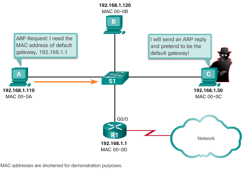 X
X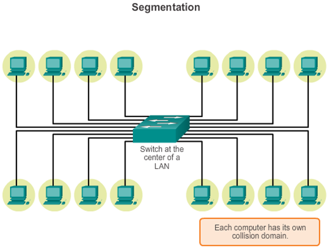
-

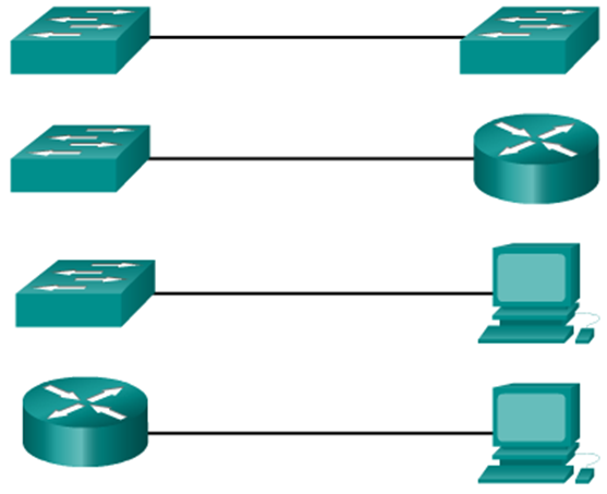
Duplex Settings
- Unidirectional data flow
- Higher potential for collision
- Hub connectivity
- Point-to-point only
- Attached to dedicated switched port
- Requires full-duplex support on both ends
- Collision-free
- Collision detect circuit disabled
Switch Fundamentals
- An Ethernet switch is a Layer 2 device, which means it uses MAC addresses to make forwarding decisions. It is completely unaware of the protocol being carried in the data portion of the frame, such as an IPv4 packet. The switch makes its forwarding decisions based only on the Layer 2 Ethernet MAC addresses.
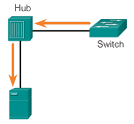
- Unlike an Ethernet hub that repeats bits out all ports except the incoming port, an Ethernet switch consults a MAC address table to make a forwarding decision for each frame. In the 📷 figure, the four-port switch was just powered on. It has not yet learned the MAC addresses for the four attached PCs.
- Note: The MAC address table is sometimes referred to as a content addressable memory (CAM) table. While the term CAM table is fairly common, for the purposes of this course, we will refer to it as a MAC address table.
Switch MAC Address Table
- 1. The switch receives a broadcast frame from PC 1 on Port 1.
- 2. The switch enters the source MAC address and the switch port that received the frame into the address table.
- 3. Because the destination address is a broadcast, the switch floods the frame to all ports, except the port on which it received the frame.
- 4. The destination device replies to the broadcast with a unicast frame addressed to PC 1.
- 5. The switch enters the source MAC address of PC 2 and the port number of the switch port that received the frame into the address table. The destination address of the frame and its associated port is found in the MAC address table.
- 6. The switch can now forward frames between source and destination devices without flooding, because it has entries in the address table that identify the associated ports.
- 📷 View Diagram
X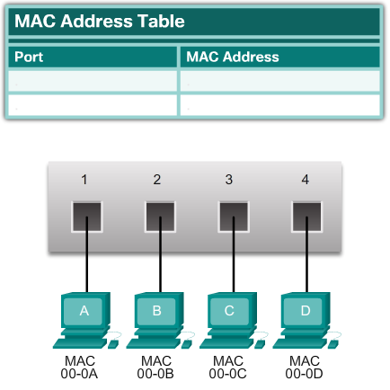 X
X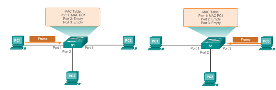
-
Frame Forwarding Methods on Cisco Switches
- Switches use one of the following forwarding methods for switching data between network ports:
- Store-and-forward switching
- Cut-through switching
- The 📷 Figure highlights differences between these two methods.
- Note: Cut-through switching is the predominant switching method used on Cisco switches.
- In store-and-forward switching, when the switch receives the frame, it stores the data in buffers until the complete frame has been received. During the storage process, the switch analyzes the frame for information about its destination. In this process, the switch also performs an error check using the Cyclic Redundancy Check (CRC) trailer portion of the Ethernet frame.
- CRC uses a mathematical formula, based on the number of bits (1s) in the frame, to determine whether the received frame has an error. After confirming the integrity of the frame, the frame is forwarded out the appropriate port, toward its destination. When an error is detected in a frame, the switch discards the frame. Discarding frames with errors reduces the amount of bandwidth consumed by corrupt data. Store-and-forward switching is required for Quality of Service (QoS) analysis on converged networks where frame classification for traffic prioritization is necessary. For example, voice over IP data streams need to have priority over web-browsing traffic.
- Click here to learn more about store-and-forward and cut-through switching.
Auto-MDIX
- MDIX auto detects the type of connection required and configures the interface accordingly
 X
X
-
Memory Buffering on Switches
- An Ethernet switch may use a buffering technique to store frames before forwarding them. Buffering may also be used when the destination port is busy due to congestion and the switch stores the frame until it can be transmitted.
- As shown in the 📷 figure, there are two methods of memory buffering: port-based and shared memory.
- Port-based Memory Buffering
- In port-based memory buffering, frames are stored in queues that are linked to specific incoming and outgoing ports. A frame is transmitted to the outgoing port only when all the frames ahead of it in the queue have been successfully transmitted. It is possible for a single frame to delay the transmission of all the frames in memory because of a busy destination port. This delay occurs even if the other frames could be transmitted to open destination ports.
- Shared Memory Buffering
- Shared memory buffering deposits all frames into a common memory buffer that all the ports on the switch share. The amount of buffer memory required by a port is dynamically allocated. The frames in the buffer are linked dynamically to the destination port. This allows the packet to be received on one port and then transmitted on another port, without moving it to a different queue.
- The switch keeps a map of frame to port links showing where a packet needs to be transmitted. The map link is cleared after the frame has been successfully transmitted. The number of frames stored in the buffer is restricted by the size of the entire memory buffer and not limited to a single port buffer. This permits larger frames to be transmitted with fewer dropped frames. This is especially important to asymmetric switching. Asymmetric switching allows for different data rates on different ports. This allows more bandwidth to be dedicated to certain ports, such as a port connected to a server.
Cut-Through Switching
- In cut-through switching, the switch acts upon the data as soon as it is received, even if the transmission is not complete. The switch buffers just enough of the frame to read the destination MAC address so that it can determine to which port to forward the data. The destination MAC address is located in the first 6 bytes of the frame following the preamble. The switch looks up the destination MAC address in its switching table, determines the outgoing interface port, and forwards the frame onto its destination through the designated switch port. The switch does not perform any error checking on the frame.
- There are two variants of cut-through switching:
- Fast-forward switching - Fast-forward switching offers the lowest level of latency. Fast-forward switching immediately forwards a packet after reading the destination address. Because fast-forward switching starts forwarding before the entire packet has been received, there may be times when packets are relayed with errors. This occurs infrequently, and the destination network adapter discards the faulty packet upon receipt. In fast-forward mode, latency is measured from the first bit received to the first bit transmitted. Fast-forward switching is the typical cut-through method of switching.
- Fragment-free switching - In fragment-free switching, the switch stores the first 64 bytes of the frame before forwarding. Fragment-free switching can be viewed as a compromise between store-and-forward switching and fast-forward switching. The reason fragment-free switching stores only the first 64 bytes of the frame is that most network errors and collisions occur during the first 64 bytes. Fragment-free switching tries to enhance fast-forward switching by performing a small error check on the first 64 bytes of the frame to ensure that a collision has not occurred before forwarding the frame. Fragment-free switching is a compromise between the high latency and high integrity of store-and-forward switching, and the low latency and reduced integrity of fast-forward switching.
- Some switches are configured to perform cut-through switching on a per-port basis until a user-defined error threshold is reached, and then they automatically change to store-and-forward. When the error rate falls below the threshold, the port automatically changes back to cut-through switching.
X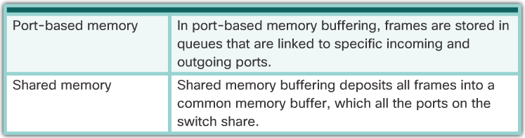
-
Layer 3 Switching
Cisco Express Forwarding
- Cisco devices which support Layer 3 switching utilize Cisco Express Forwarding (CEF). Two main components of CEF operation are the:
- Forwarding Information Base (FIB)
- Conceptually it is similar to a routing table.
- A networking device uses this lookup table to make destination-based switching decisions during Cisco Express Forwarding operation.
- Updated when changes occur in the network and contains all routes known at the time.
- Adjacency Tables
- Maintain layer 2 next-hop addresses for all FIB entries.
Types of Layer 3 Interfaces
- The major types of Layer 3 interfaces are:
- Switch Virtual Interface (SVI) – Logical interface on a switch associated with a virtual local-area network (VLAN).
- Routed Port – Physical port on a Layer 3 switch configured to act as a router port. Configure routed ports by putting the interface into Layer 3 mode with the no switchport interface configuration command.
- Layer 3 EtherChannel – Logical interface on a Cisco device associated with a bundle of routed ports.
- 📷 Configuring a Routed Port on a Layer 3 Switch
X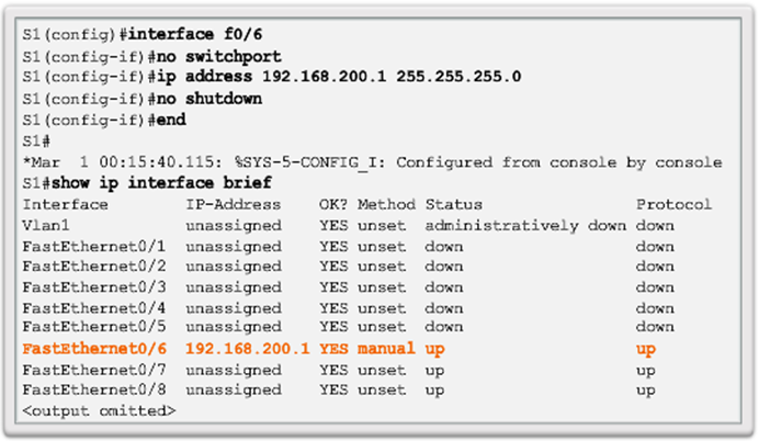
-
Summary
- Ethernet is the most widely used LAN technology used today.
- Ethernet standards define both the Layer 2 protocols and the Layer 1 technologies.
- The Ethernet frame structure adds headers and trailers around the Layer 3 PDU to encapsulate the message being sent.
- As an implementation of the IEEE 802.2/3 standards, the Ethernet frame provides MAC addressing and error checking.
- Replacing hubs with switches in the local network has reduced the probability of frame collisions in half-duplex links.
- The Layer 2 addressing provided by Ethernet supports unicast, multicast, and broadcast communications.
- Ethernet uses the Address Resolution Protocol to determine the MAC addresses of destinations and map them against known Network layer addresses.
- Each node on an IP network has both a MAC address and an IP address.
- The ARP protocol resolves IPv4 addresses to MAC addresses and maintains a table of mappings.
- A Layer 2 switch builds a MAC address table that it uses to make forwarding decisions.
- Layer 3 switches are also capable of performing Layer 3 routing functions, reducing the need for dedicated routers on a LAN.
- Layer 3 switches have specialized switching hardware so they can typically route data as quickly as they can switch.