-

Chapter 7: Objectives
- Upon completion of this chapter, you will be able to:
- Describe the structure of an IPv4 address.
- Describe the purpose of the subnet mask.
- Compare the characteristics and uses of the unicast, broadcast, and multicast IPv4 addresses.
- Compare the use of public address space and private address space.
- Explain the need for IPv6 addressing.
- Describe the representation of an IPv6 address.
- Describe types of IPv6 network addresses.
- Configure global unicast addresses.
- Describe multicast addresses.
- Describe the role of ICMP in an IP network. (Include IPv4 and IPv6.)
- Use ping and traceroute utilities to test network connectivity.
Chapter 7
- IPv4 Network Addresses
- IPv6 Network Addresses
- Connectivity Verification
- Summary
-
Positional Notation
 Radix
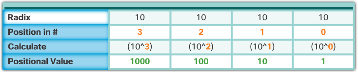
Radix- The first row identifies the number base or radix. The decimal notation system is based on 10 therefore the radix is 10.
 Radix
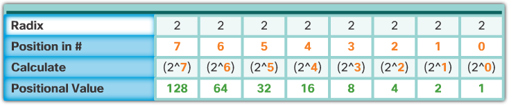
Radix- The binary notation system is based on 2, therefore the radix is 2.
- Learning to convert binary to decimal requires an understanding of positional notation. Positional notation means that a digit represents different values depending on the “position” the digit occupies in the sequence of numbers. You already know the most common numbering system, the decimal (base 10) notation system.
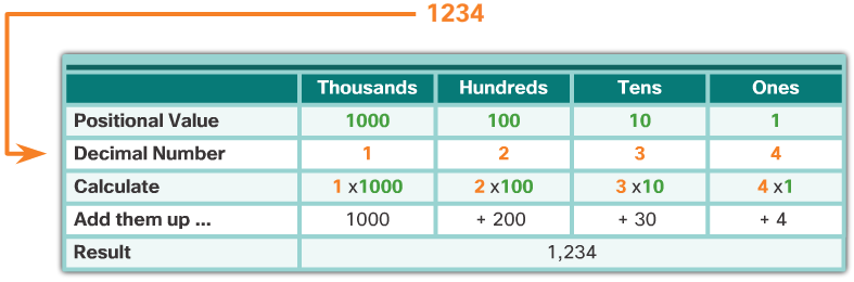
- The decimal positional notation system operates as described in Figure 1. Click the row titles for a description of each row. To use the positional system, match a given number to its positional value. The example in Figure 2 illustrates how positional notation is used with the decimal number 1234.
- In contrast, the binary positional notation operates as described in Figure 3. Click the row titles for a description of each row.
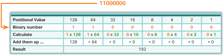
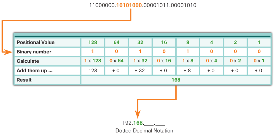
- The example in Figure 4 illustrates how a binary number 11000000 corresponds to the number 192. If the binary number had been 10101000, then the corresponding decimal number would be 168.
IPv4 Addresses
- Binary is a numbering system that consists of the numbers 0 and 1 called bits. In contrast, the decimal numbering system consists of 10 digits consisting of the numbers 0 – 9.
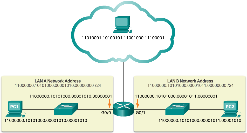
- Binary is important for us to understand because hosts, servers, and network devices use binary addressing. Specifically, they use binary IPv4 addresses, as shown in Figure 1, to identify each other.
- Each address consists of a string of 32 bits, divided into four sections called octets. Each octet contains 8 bits (or 1 byte) separated with a dot. For example, PC1 in the figure is assigned IPv4 address 11000000.10101000.00001010.00001010. Its default gateway address would be that of R1 Gigabit Ethernet interface 11000000.10101000.00001010.00000001.
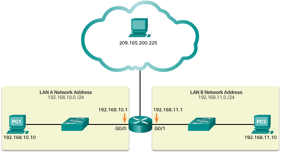
- Working with binary numbers can be challenging. For ease of use by people, IPv4 addresses are commonly expressed in dotted decimal notation as shown in Figure 2. PC1 is assigned IPv4 address 192.168.10.10, and its default gateway address is 192.168.10.1.
- For a solid understanding of network addressing, it is necessary to know binary addressing and gain practical skills converting between binary and dotted decimal IPv4 addresses.
-
Decimal to Binary Conversion
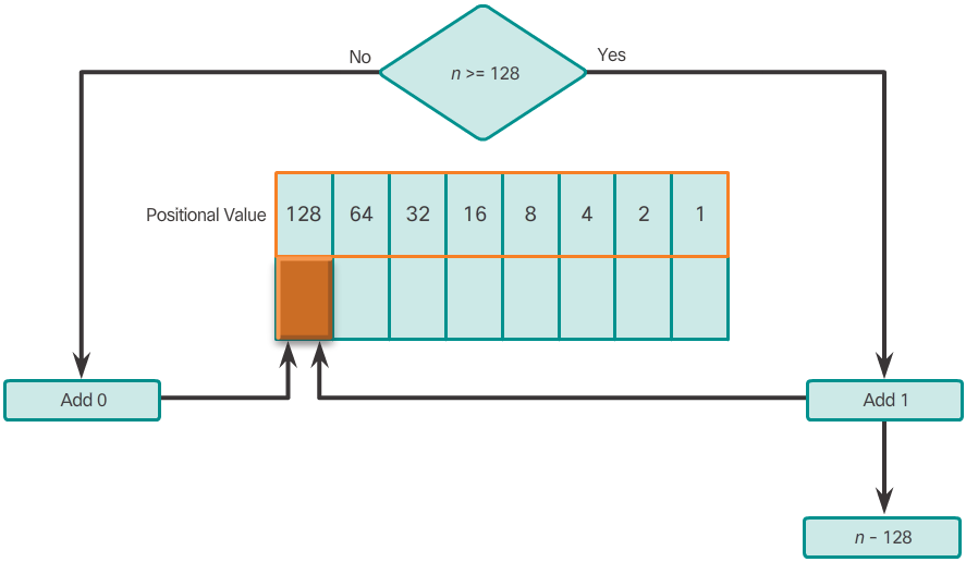
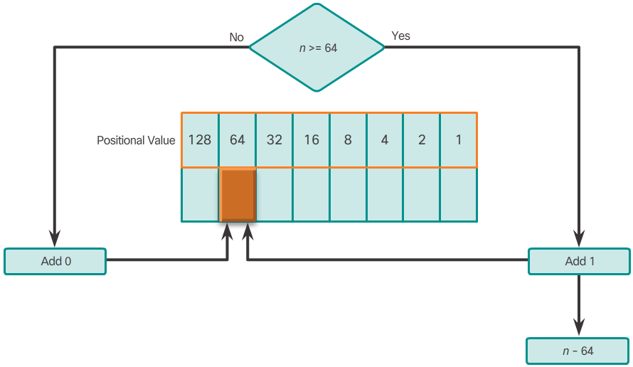
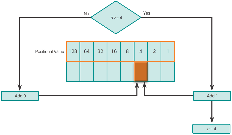
- It is also necessary to understand how to convert a dotted decimal IPv4 address to binary. A useful tool is the binary positional value table. The following illustrates how to use the table to convert decimal to binary:
- Figure 1 questions if the decimal number of the octet (n) is equal to or greater than the most-significant bit (128). If no, then enter binary 0 in the 128 positional value. If yes, then add a binary 1 in the 128 positional value and subtract 128 from the decimal number.
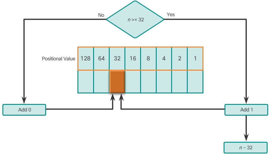
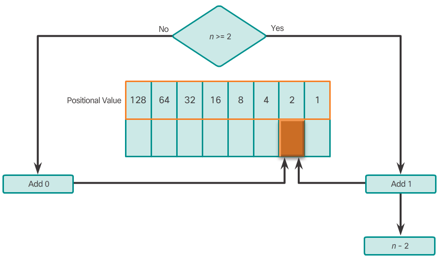
- Figure 2 questions if the remainder (n) is equal to or greater than the next most-significant bit (64). If no, then add a binary 0 in the 64 positional value, otherwise add binary 1 and subtract 64 from the decimal.
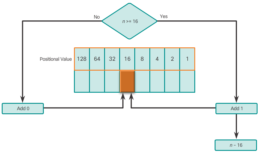
- Figure 3 questions if the remainder (n) is equal to or greater than the next most-significant bit (32). If no, then add a binary 0 in the 32 positional value, otherwise add binary 1 and subtract 32 from the decimal.
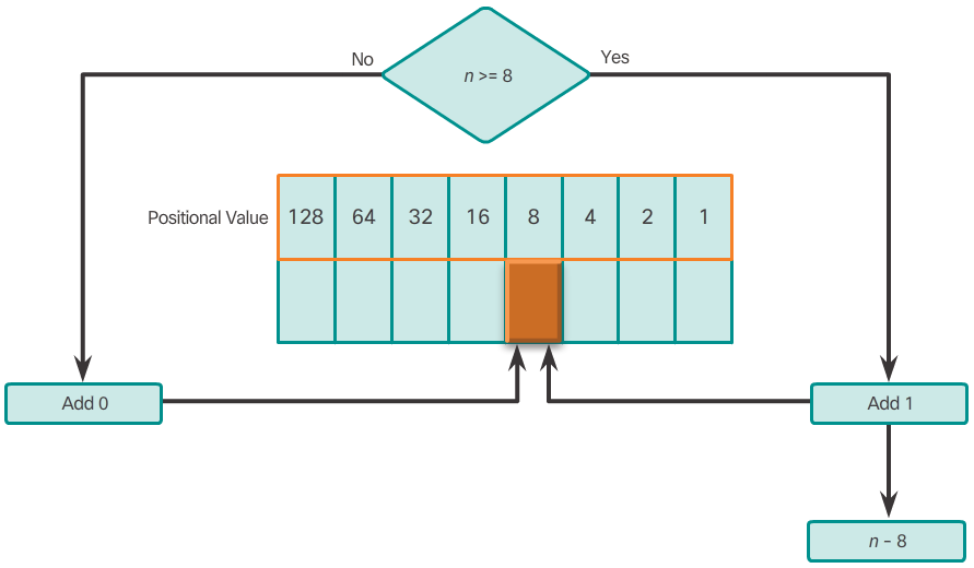
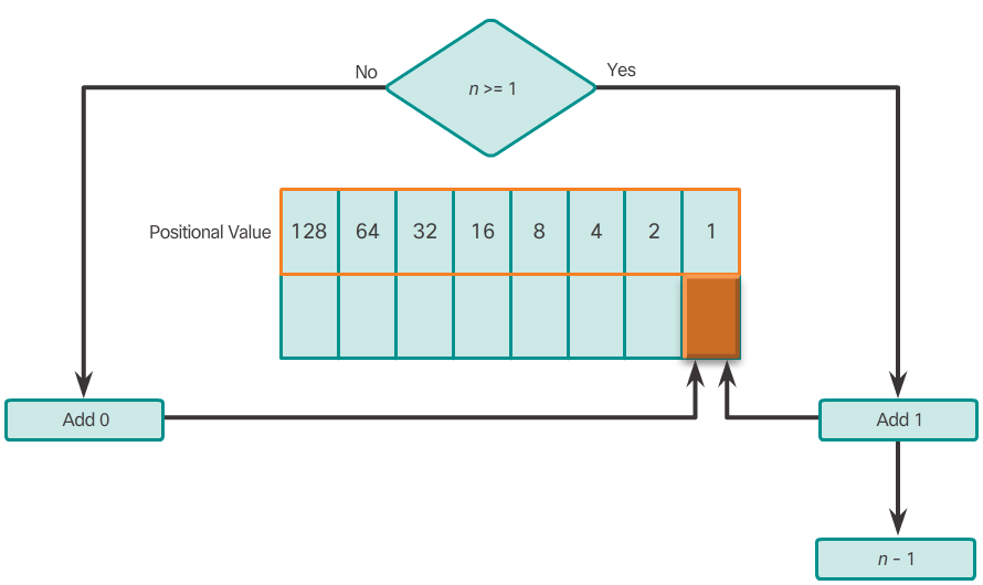
- Figures 4 through 8 continue to evaluate the decimal until all positional values have been entered resulting in the equivalent binary value.
Binary to Decimal Conversion
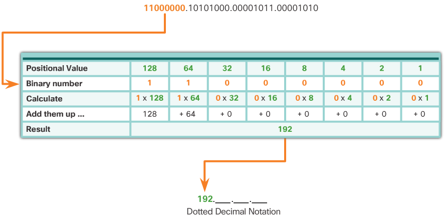
- To convert a binary IPv4 address to its dotted decimal equivalent, divide the IPv4 address into four 8-bit octets. Next apply the binary positional value to the first octet binary number and calculate accordingly.
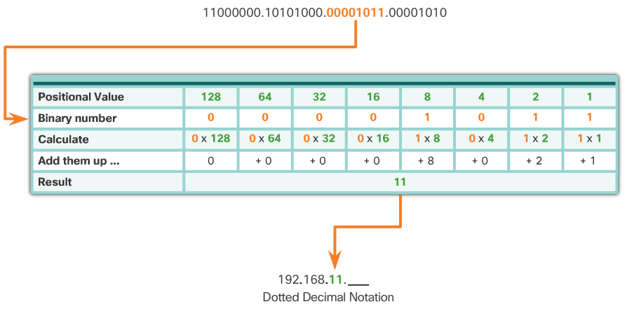
- For example, consider that 11000000.10101000.00001011.00001010 is the binary IPv4 address of a host. To convert the binary address to decimal, start with the first octet as shown in Figure 1. Enter the 8-bit binary number under the positional value of row 1 and then calculate to produce the decimal number 192. This number goes into the first octet of the dotted decimal notation.
- Next convert the second octet as shown in Figure 2. The resulting decimal value is 168, and it goes into the second octet.
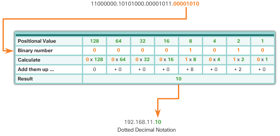
- Convert the third octet as shown in Figure 3 and the fourth octet as shown in Figure 4 which completes the IP address and produces 192.168.11.10.
-
Network and Host Portions
- Understanding binary notation is important when determining if two hosts are in the same network. Recall that an IPv4 address is a hierarchical address that is made up of a network portion and a host portion. When determining the network portion versus the host portion, it is necessary to look at the 32-bit stream. Within the 32-bit stream, a portion of the bits identify the network, and a portion of the bits identify the host as shown in the 📷 figure.
- The bits within the network portion of the address must be identical for all devices that reside in the same network. The bits within the host portion of the address must be unique to identify a specific host within a network. If two hosts have the same bit-pattern in the specified network portion of the 32-bit stream, those two hosts will reside in the same network.
- But how do hosts know which portion of the 32-bits identifies the network and which identifies the host? That is the job of the subnet mask.
The Subnet Mask
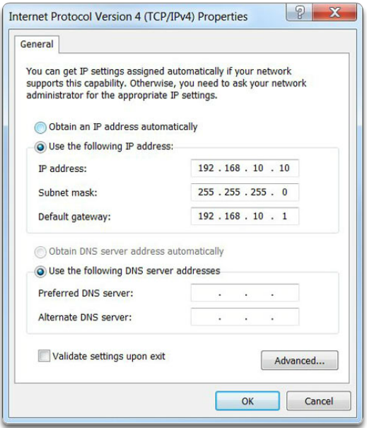
- As shown in Figure 1, three dotted decimal IPv4 addresses must be configured when assigning an IPv4 configuration to host:
- IPv4 address – Unique IPv4 address of the host
- Subnet mask - Used to identify the network/host portion of the IPv4 address
- Default gateway – Identifies the local gateway (i.e. local router interface IPv4 address) to reach remote networks
- When an IPv4 address is assigned to a device, the subnet mask is used to determine the network address where the device belongs. The network address represents all the devices on the same network.
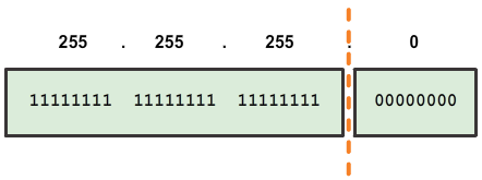
- Figure 2 displays the dotted decimal address and the 32-bit subnet mask. Notice how the subnet mask is essentially a sequence of 1 bits followed by a sequence of 0 bits.
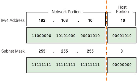
- To identify the network and host portions of an IPv4 address, the subnet mask is compared to the IPv4 address bit for bit, from left to right as shown in Figure 3. The 1s in the subnet mask identify the network portion while the 0s identify the host portion. Note that the subnet mask does not actually contain the network or host portion of an IPv4 address, it just tells the computer where to look for these portions in a given IPv4 address.
- The actual process used to identify the network portion and host portion is called ANDing.
X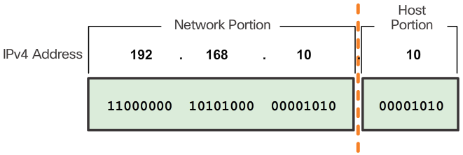
-
The Prefix Length
- Expressing network addresses and host addresses with the dotted decimal subnet mask address can become cumbersome. Fortunately, there is an alternate shorthand method of identifying a subnet mask called the prefix length.
- Specifically, the prefix length is the number of bits set to 1 in the subnet mask. It is written in “slash notation”, which is a “/” followed by the number of bits set to 1. Therefore, count the number of bits in the subnet mask and prepend it with a slash.
- For example, refer to the table in the 📷 figure. The first column lists various subnet masks that can be used with a host address. The second column displays the converted 32-bit binary address. The last column displays the resulting prefix length.
- Using various types of prefix lengths will be discussed later. For now, the focus will be on the /24 (i.e. 255.255.255.0) subnet mask.
Network, Host, and Broadcast Addresses
- Each network address contains (or identifies) host addresses and a broadcast address.
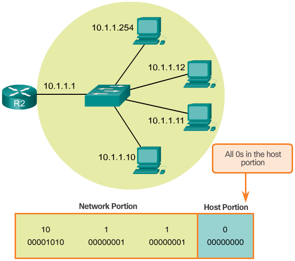
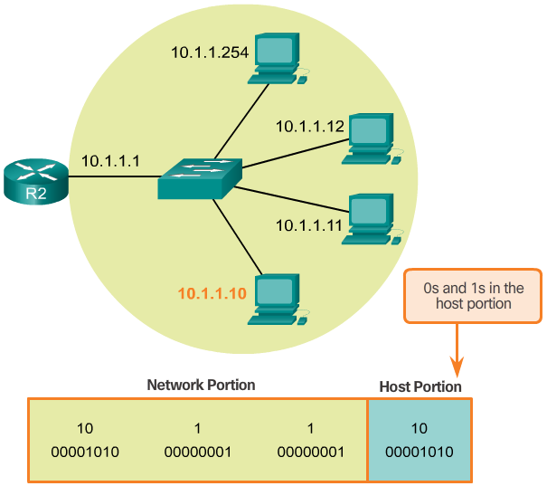
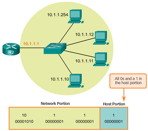
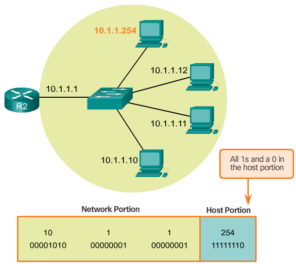
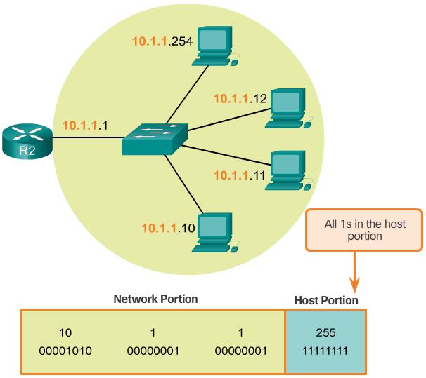
- For another example, refer to Figures 1 through 5. In these figures, notice how the network portion of the addresses remains the same while the host portion changes.
- Figure 1 displays the network address 10.1.1.0 /24. Host bits are all 0s.
- Figure 2 displays the IPv4 address of host 10.1.1.10. Host bits are a mix of 0s and 1s.
- Figure 3 displays the first host IPv4 address 10.1.1.1. Host bits are all 0s with a 1. Notice that it is assigned to the router interface, and therefore, would become the default gateway for all of the hosts on that network.
- Figure 4 displays the last host IPv4 address 10.1.1.254. Host bits are all 1s and a 0.
- Figure 5 displays the broadcast address 10.1.1.255. Host bits are all 1s.
- The concepts discussed in this topic form the basis for understanding IPv4 addressing. Make sure you understand how a network address identifies a network portion and host portion using the subnet mask or prefix length and the ANDing operation. Also make note of the various types of network addresses within a network.
XSubnet Mask 32-bit Address Prefix Length 255.0.0.0 11111111.00000000.00000000.00000000 /8 255.255.0.0 11111111.11111111.00000000.00000000 /16 255.255.255.0 11111111.11111111.11111111.00000000 /24 255.255.255.128 11111111.11111111.11111111.10000000 /25 255.255.255.192 11111111.11111111.11111111.11000000 /26 255.255.255.224 11111111.11111111.11111111.11100000 /27 255.255.255.240 11111111.11111111.11111111.11110000 /28 255.255.255.248 11111111.11111111.11111111.11111000 /29 255.255.255.252 11111111.11111111.11111111.11111100 /30 -
Broadcast Transmission
- Broadcast traffic is used to send packets to all hosts in the network using the broadcast address for the network. With a broadcast, the packet contains a destination IPv4 address with all ones (1s) in the host portion. This means that all hosts on that local network (broadcast domain) will receive and look at the packet. Many network protocols, such as DHCP, use broadcasts. When a host receives a packet sent to the network broadcast address, the host processes the packet as it would a packet addressed to its unicast address.
- Broadcast may be directed or limited. A directed broadcast is sent to all hosts on a specific network. For example, a host on the 172.16.4.0/24 network sends a packet to 172.16.4.255. A limited broadcast is sent to 255.255.255.255. By default, routers do not forward broadcasts.
- As an example, a host within the 172.16.4.0/24 network would broadcast to all hosts in its network using a packet with a destination address of 255.255.255.255.
- When a packet is broadcast, it uses resources on the network and causes every receiving host on the network to process the packet. Therefore, broadcast traffic should be limited so that it does not adversely affect the performance of the network or devices. Because routers separate broadcast domains, subdividing networks can improve network performance by eliminating excessive broadcast traffic.
Multicast Transmission
- Multicast transmission reduces traffic by allowing a host to send a single packet to a selected set of hosts that subscribe to a multicast group.
- IPv4 has reserved the 224.0.0.0 to 239.255.255.255 addresses as a multicast range. The IPv4 multicast addresses 224.0.0.0 to 224.0.0.255 are reserved for multicasting on the local network only. These addresses are to be used for multicast groups on a local network. A router connected to the local network recognizes that these packets are addressed to a local network multicast group and never forwards them further. A typical use of reserved local network multicast address is in routing protocols using multicast transmission to exchange routing information. For instance, 224.0.0.9 is the multicast address used by Routing Information Protocol (RIP) version 2 to communicate with other RIPv2 routers.
- Hosts that receive particular multicast data are called multicast clients. The multicast clients use services requested by a client program to subscribe to the multicast group.
- Each multicast group is represented by a single IPv4 multicast destination address. When an IPv4 host subscribes to a multicast group, the host processes packets addressed to this multicast address, and packets addressed to its uniquely allocated unicast address.
Static IPv4 Address Assignment to a Host
- Devices can be assigned an IP address either statically or dynamically.
- In networks, some devices require a fixed IP address. For instance, printers, servers, and networking devices need an IP address that does not change. For this reason, these devices are typically assigned static IP addresses.
- A host can also be configured with a static IPv4 address such as shown in the 📷 figure. Assigning hosts static IP addresses is acceptable in small networks. However, it would be time-consuming to enter static addresses on each host in a large network. It is important to maintain an accurate list of static IP addresses assigned to each device.
Dynamic IPv4 Address Assignment to a Host
- In most data networks, the largest population of hosts includes PCs, tablets, smartphones, printers, and IP phones. It is also often the case that the user population and their devices change frequently. It would be impractical to statically assign IPv4 addresses for each device. Therefore, these devices are assigned IPv4 addresses dynamically using the Dynamic Host Configuration Protocol (DHCP).
- As shown in the 📷 figure, a host can obtain IP addressing information automatically. The host is a DHCP client and requests IP address information from a DHCP server. The DHCP server provides an IP address, subnet mask, default gateway, and other configuration information.
- DHCP is generally the preferred method of assigning IPv4 addresses to hosts on large networks. An additional benefit of DHCP is the address is not permanently assigned to a host but is only "leased" for a period of time. If the host is powered down or taken off the network, the address is returned to the pool for reuse. This feature is especially helpful for mobile users that come and go on a network.
Unicast Transmission
- Unicast communication is used for normal host-to-host communication in both a client/server and a peer-to-peer network. Unicast packets use the address of the destination device as the destination address and can be routed through an internetwork.
- In an IPv4 network, the unicast address applied to an end device is referred to as the host address. For unicast communication, the addresses assigned to the two end devices are used as the source and destination IPv4 addresses. During the encapsulation process, the source host uses its IPv4 address as the source address and the IPv4 address of the destination host as the destination address. Regardless of whether the destination specified a packet as a unicast, broadcast or multicast; the source address of any packet is always the unicast address of the originating host.
- Note: In this course, all communication between devices is unicast unless otherwise noted.
- IPv4 unicast host addresses are in the address range of 0.0.0.0 to 223.255.255.255. However, within this range are many addresses that are reserved for special purposes. These special purpose addresses will be discussed later in this chapter.
X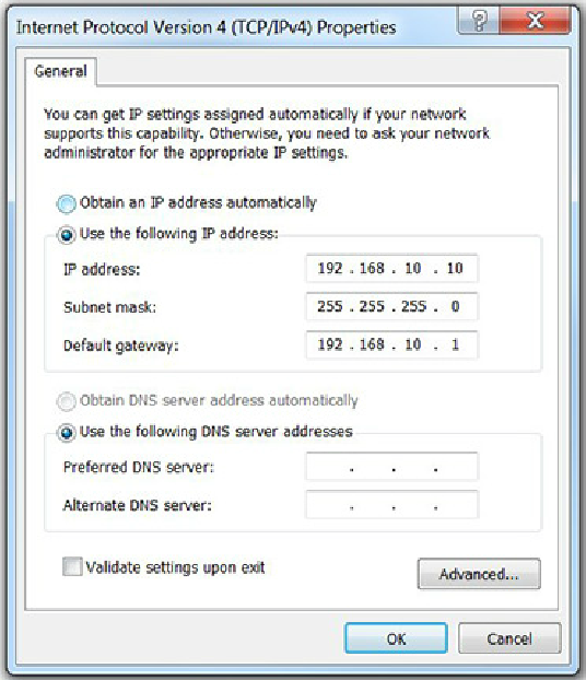 X
X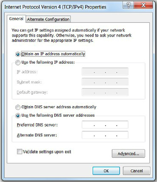
-
Legacy Classful Addressing
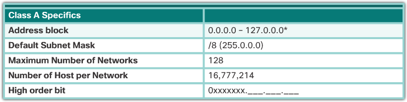
- In 1981, Internet IPv4 addresses were assigned using classful addressing as defined in RFC 790, Assigned Numbers. The RFC divided the unicast ranges into specific classes called:
- Class A (0.0.0.0/8 to 127.0.0.0/8) – Designed to support extremely large networks with more than 16 million host addresses. It used a fixed /8 prefix with the first octet to indicate the network address and the remaining three octets for host addresses. All class A addresses required that the most significant bit of the high-order octet be a zero creating a total of 128 possible class A networks. Figure 1 summarizes the class A.
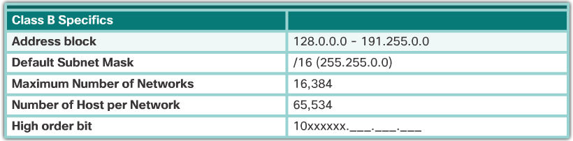
- Class B (128.0.0.0 /16 – 191.255.0.0 /16) – Designed to support the needs of moderate to large size networks with up to approximately 65,000 host addresses. It used a fixed /16 prefix with the two high-order octets to indicate the network address and the remaining two octets for host addresses. The most significant two bits of the high-order octet must be 10 creating over 16,000 networks. Figure 2 summarizes the class B.
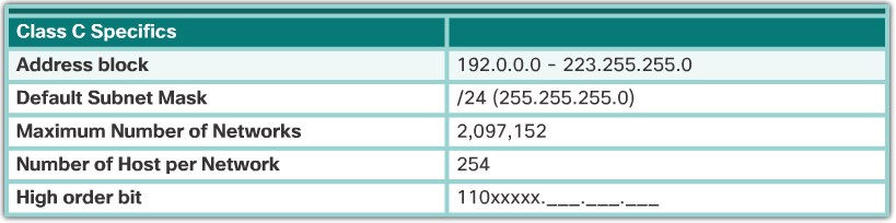
- Class C (192.0.0.0 /24 – 223.255.255.0 /24) – Designed to support small networks with a maximum of 254 hosts. It used a fixed /24 prefix with the first three octets to indicate the network and the remaining octet for the host addresses. The most significant three bits of the high-order octet must be 110 creating over 2 million possible networks. Figure 3 summarizes the class C.
- Note: There is also a Class D multicast block consisting of 224.0.0.0 to 239.0.0.0 and a Class E experimental address block consisting of 240.0.0.0 – 255.0.0.0.
Assignment of IP Addresses
- For a company or organization to support network hosts, such as web servers accessible from the Internet, that organization must have a block of public addresses assigned. Remember that public addresses must be unique, and use of these public addresses is regulated and allocated to each organization separately. This is true for IPv4 and IPv6 addresses.
- Both IPv4 and IPv6 addresses are managed by the Internet Assigned Numbers Authority (IANA) (http://www.iana.org). The IANA manages and allocates blocks of IP addresses to the Regional Internet Registries (RIRs).
- RIRs are responsible for allocating IP addresses to ISPs who in turn provide IPv4 address blocks to organizations and smaller ISPs. Organizations can get their addresses directly from an RIR subject to the policies of that RIR.
Public and Private IPv4 Addresses
- Public IPv4 addresses are addresses which are globally routed between ISP (Internet Service Provider) routers. However, not all available IPv4 addresses can be used on the Internet. There are blocks of addresses called private addresses that are used by most organizations to assign IPv4 addresses to internal hosts.
- In the mid-1990s private IPv4 addresses were introduced because of the depletion of IPv4 address space. Private IPv4 addresses are not unique and can be used by an internal network.
- Specifically, the private address blocks are:
- 10.0.0.0 /8 or 10.0.0.0 to 10.255.255.255
- 172.16.0.0 /12 or 172.16.0.0 to 172.31.255.255
- 192.168.0.0 /16 or 192.168.0.0 to 192.168.255.255
- It is important to know that addresses within these address blocks are not allowed on the Internet and must be filtered (discarded) by Internet routers. For example, in the 📷 figure, users in networks 1, 2, or 3 are sending packets to remote destinations. The Internet Service Provider (ISP) routers would see that the source IPv4 addresses in the packets are from private addresses and would, therefore, discard the packets.
- Note: Private addresses are defined in RFC 1918.
- Most organizations use private IPv4 addresses for their internal hosts. However, these RFC 1918 address are not routable in the Internet and must be translated to a public IPv4 address. Network Address Translation (NAT) is used to translate between private IPv4 and public IPv4 addresses. This is usually done on the router that connects the internal network to the ISP's network.
- Home routers provide the same capability. For instance, most home routers assign IPv4 addresses to their wired and wireless hosts from the private address of 192.168.1.0 /24. The home router interface that connects to the Internet service provider (ISP) network is assigned a public IPv4 address to use on the Internet.
Special User IPv4 Addresses
- There are certain addresses such as the network address and broadcast address that cannot be assigned to hosts. There are also special addresses that can be assigned to hosts, but with restrictions on how those hosts can interact within the network.
- Loopback addresses (127.0.0.0 /8 or 127.0.0.1 to 127.255.255.254) – More commonly identified as only 127.0.0.1, these are special addresses used by a host to direct traffic to itself. For example, it can be used on a host to test if the TCP/IP configuration is operational, such as shown in the 📷 figure. Notice how the 127.0.0.1 loopback address replies to the ping command. Also note how any address within this block will loop back to the local host, such as shown with the second ping in the figure.
- Link-Local addresses (169.254.0.0 /16 or 169.254.0.1 to 169.254.255.254) – More commonly known as the Automatic Private IP Addressing (APIPA) addresses, they are used by a Windows DHCP client to self-configure in the event that there are no DHCP servers available.Useful in a peer-to-peer connection.
- TEST-NET addresses (192.0.2.0/24 or 192.0.2.0 to 192.0.2.255) – These addresses are set aside for teaching and learning purposes and can be used in documentation and network examples.
- Note: There are also Experimental Addresses in the block 240.0.0.0 to 255.255.255.254 that are reserved for future use (RFC 3330).
X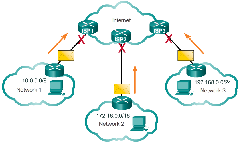 X
X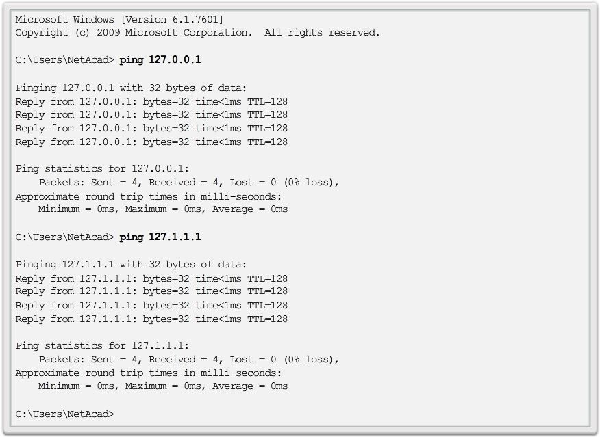
-
IPv4 and IPv6 Coexistence
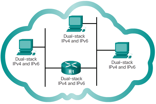
- There is not a single date to move to IPv6. For the foreseeable future, both IPv4 and IPv6 will coexist. The transition is expected to take years. The IETF has created various protocols and tools to help network administrators migrate their networks to IPv6. The migration techniques can be divided into three categories:
- Dual Stack – As shown in Figure 1, dual stack allows IPv4 and IPv6 to coexist on the same network segment. Dual stack devices run both IPv4 and IPv6 protocol stacks simultaneously.
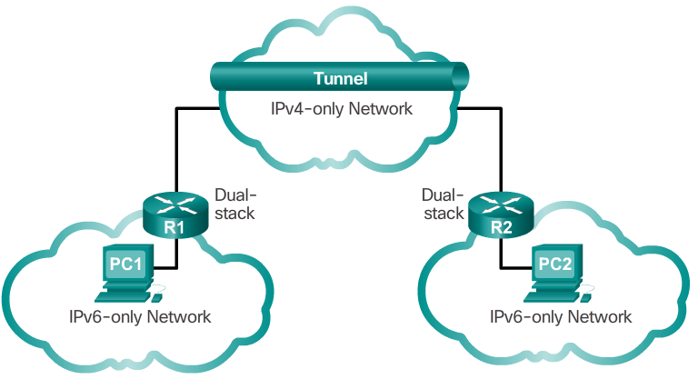
- Tunneling – As shown in Figure 2, tunneling is a method of transporting an IPv6 packet over an IPv4 network. The IPv6 packet is encapsulated inside an IPv4 packet, similar to other types of data.
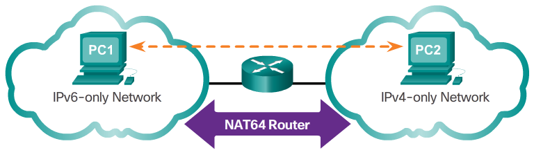
- Translation – As shown in Figure 3, Network Address Translation 64 (NAT64) allows IPv6-enabled devices to communicate with IPv4-enabled devices using a translation technique similar to NAT for IPv4. An IPv6 packet is translated to an IPv4 packet and vice versa.
- Note: Tunneling and translation are only used where needed. The goal should be native IPv6 communications from source to destination.
The Need for IPv6
- IPv6 is designed to be the successor to IPv4. IPv6 has a larger 128-bit address space, providing for 340 undecillion addresses. (That is the number 340, followed by 36 zeroes.) However, IPv6 is more than just larger addresses. When the IETF began its development of a successor to IPv4, it used this opportunity to fix the limitations of IPv4 and include additional enhancements. One example is Internet Control Message Protocol version 6 (ICMPv6), which includes address resolution and address auto-configuration not found in ICMP for IPv4 (ICMPv4). ICMPv4 and ICMPv6 will be discussed later.
- Need for IPv6
- The depletion of IPv4 address space has been the motivating factor for moving to IPv6. As Africa, Asia and other areas of the world become more connected to the Internet, there are not enough IPv4 addresses to accommodate this growth. Four out of the five RIRs have run out of IPv4 addresses.
- IPv4 has a theoretical maximum of 4.3 billion addresses. Private addresses in combination with Network Address Translation (NAT) have been instrumental in slowing the depletion of IPv4 address space. However, NAT breaks many applications and has limitations that severely impede peer-to-peer communications.
- Internet of Everything
- The Internet of today is significantly different than the Internet of past decades. The Internet of today is more than email, web pages, and file transfer between computers. The evolving Internet is becoming an Internet of things. No longer will the only devices accessing the Internet be computers, tablets, and smartphones. The sensor-equipped, Internet-ready devices of tomorrow will include everything from automobiles and biomedical devices, to household appliances and natural ecosystems.
- With an increasing Internet population, a limited IPv4 address space, issues with NAT and an Internet of Everything, the time has come to begin the transition to IPv6.
-
Rule 1 – Omit Leading 0s
- The first rule to help reduce the notation of IPv6 addresses is to omit any leading 0s (zeros) in any 16-bit section or hextet. For example:
- 01AB can be represented as 1AB
- 09F0 can be represented as 9F0
- 0A00 can be represented as A00
- 00AB can be represented as AB
- This rule only applies to leading 0s, NOT to trailing 0s, otherwise the address would be ambiguous. For example, the hextet “ABC” could be either “0ABC” or “ABC0”, but these do not represent the same value.
Rule 2 – Omit All 0 Segments
- The second rule to help reduce the notation of IPv6 addresses is that a double colon (::) can replace any single, contiguous string of one or more 16-bit segments (hextets) consisting of all 0s.
- The double colon (::) can only be used once within an address, otherwise there would be more than one possible resulting address. When used with the omitting leading 0s technique, the notation of IPv6 address can often be greatly reduced. This is commonly known as the compressed format.
- Incorrect address:
- 2001:0DB8::ABCD::1234
- Possible expansions of ambiguous compressed addresses:
- 2001:0DB8::ABCD:0000:0000:1234
- 2001:0DB8::ABCD:0000:0000:0000:1234
- 2001:0DB8:0000:ABCD::1234
- 2001:0DB8:0000:0000:ABCD::1234
Examples
- 📷 Example 1
- 📷 Example 2
IPv6 Address Representation
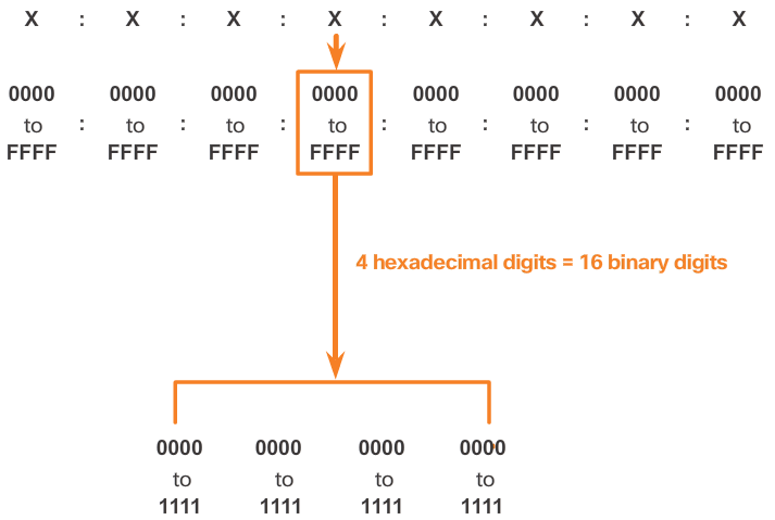
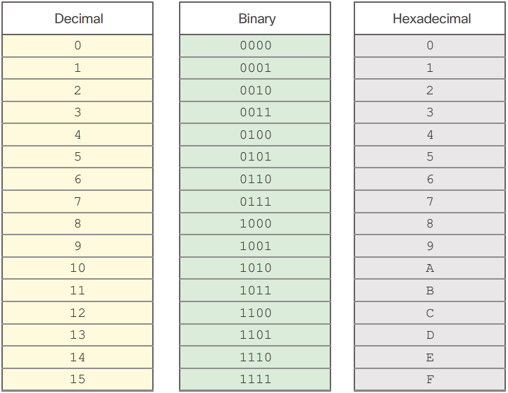
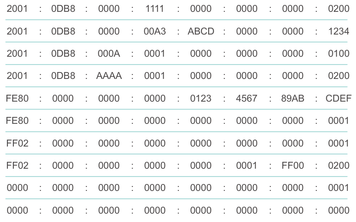
- IPv6 addresses are 128 bits in length and written as a string of hexadecimal values. Every 4 bits is represented by a single hexadecimal digit; for a total of 32 hexadecimal values, as shown in Figure 1. IPv6 addresses are not case-sensitive and can be written in either lowercase or uppercase.
- Preferred Format
- As shown in Figure 1, the preferred format for writing an IPv6 address is x:x:x:x:x:x:x:x, with each “x” consisting of four hexadecimal values. When referring to 8 bits of an IPv4 address we use the term octet. In IPv6, a hextet is the unofficial term used to refer to a segment of 16 bits or four hexadecimal values. Each “x” is a single hextet, 16 bits or four hexadecimal digits.
- Preferred format means the IPv6 address is written using all 32 hexadecimal digits. It does not necessarily mean it is the ideal method for representing the IPv6 address. In the following pages, we will see two rules to help reduce the number of digits needed to represent an IPv6 address.
- Figure 2 is a review of the relationship between decimal, binary and hexadecimal. Figure 3 has examples of IPv6 addresses in the preferred format.
X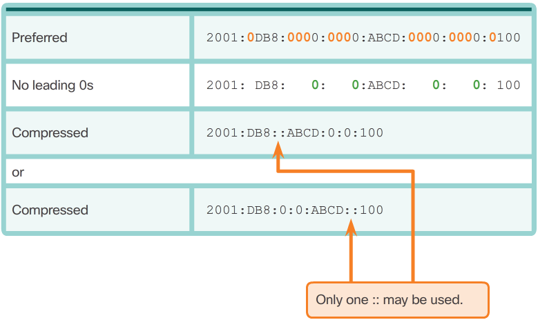 X
X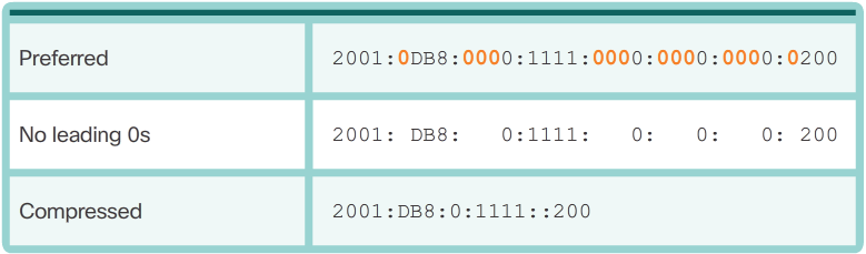
-
IPv6 Unicast Addresses cont...
- Unique local
- Another type of unicast address is the unique local unicast address. IPv6 unique local addresses have some similarity to RFC 1918 private addresses for IPv4, but there are significant differences. Unique local addresses are used for local addressing within a site or between a limited number of sites. These addresses should not be routable in the global IPv6 and should not be translated to a global IPv6 address. Unique local addresses are in the range of FC00::/7 to FDFF::/7.
- With IPv4, private addresses are combined with NAT/PAT to provide a many-to-one translation of private-to-public addresses. This is done because of the limited availability of IPv4 address space. Many sites also use the private nature of RFC 1918 addresses to help secure or hide their network from potential security risks. However, this was never the intended use of these technologies, and the IETF has always recommended that sites take the proper security precautions on their Internet-facing router. Unique local addresses can be used for devices that will never need or have access from another network.
IPv6 Link-Local Unicast Addresses
- An IPv6 link-local address enables a device to communicate with other IPv6-enabled devices on the same link and only on that link (subnet). Packets with a source or destination link-local address cannot be routed beyond the link from which the packet originated.
- The global unicast address is not a requirement. However, every IPv6-enabled network interface is required to have a link-local address.
- If a link-local address is not configured manually on an interface, the device will automatically create its own without communicating with a DHCP server. IPv6-enabled hosts create an IPv6 link-local address even if the device has not been assigned a global unicast IPv6 address. This allows IPv6-enabled devices to communicate with other IPv6-enabled devices on the same subnet. This includes communication with the default gateway (router).
- IPv6 link-local addresses are in the FE80::/10 range. The /10 indicates that the first 10 bits are 1111 1110 10xx xxxx. The first hextet has a range of 1111 1110 1000 0000 (FE80) to 1111 1110 1011 1111 (FEBF).
- This 📷 figure shows an example of communication using IPv6 link-local addresses.
- This 📷 figure shows some of the uses for IPv6 link-local addresses.
- Note: Typically, it is the link-local address of the router and not the global unicast address, that is used as the default gateway for other devices on the link.
IPv6 Prefix Length
- Recall that the prefix, or network portion, of an IPv4 address, can be identified by a dotted-decimal subnet mask or prefix length (slash notation). For example, an IPv4 address of 192.168.1.10 with dotted-decimal subnet mask 255.255.255.0 is equivalent to 192.168.1.10/24.
- IPv6 uses the prefix length to represent the prefix portion of the address. IPv6 does not use the dotted-decimal subnet mask notation. The prefix length is used to indicate the network portion of an IPv6 address using the IPv6 address/prefix length.
- The prefix length can range from 0 to 128. A typical IPv6 prefix length for LANs and most other types of networks is /64. This means the prefix or network portion of the address is 64 bits in length, leaving another 64 bits for the interface ID (host portion) of the address.
IPv6 Address Types
- There are three types of IPv6 addresses:
- Unicast - An IPv6 unicast address uniquely identifies an interface on an IPv6-enabled device. As shown in the figure, a source IPv6 address must be a unicast address.
- Multicast - An IPv6 multicast address is used to send a single IPv6 packet to multiple destinations.
- Anycast - An IPv6 anycast address is any IPv6 unicast address that can be assigned to multiple devices. A packet sent to an anycast address is routed to the nearest device having that address. Anycast addresses are beyond the scope of this course.
- Unlike IPv4, IPv6 does not have a broadcast address. However, there is an IPv6 all-nodes multicast address that essentially gives the same result.
IPv6 Unicast Addresses
- An IPv6 unicast address uniquely identifies an interface on an IPv6-enabled device. A packet sent to a unicast address is received by the interface that is assigned that address. Similar to IPv4, a source IPv6 address must be a unicast address. The destination IPv6 address can be either a unicast or a multicast address.
- The most common types of IPv6 unicast addresses are global unicast addresses (GUA) and link-local unicast addresses.
- Global unicast
- A global unicast address is similar to a public IPv4 address. These are globally unique, Internet routable addresses. Global unicast addresses can be configured statically or assigned dynamically.
- Link-local
- Link-local addresses are used to communicate with other devices on the same local link. With IPv6, the term link refers to a subnet. Link-local addresses are confined to a single link. Their uniqueness must only be confirmed on that link because they are not routable beyond the link. In other words, routers will not forward packets with a link-local source or destination address.
X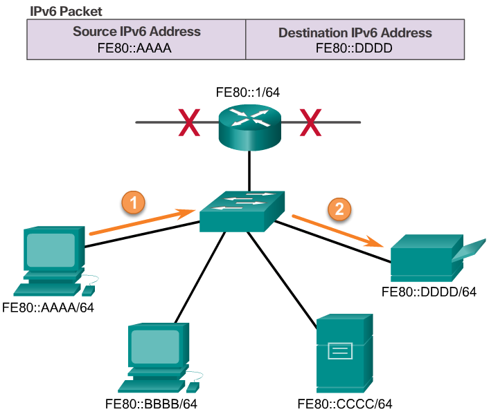 X
X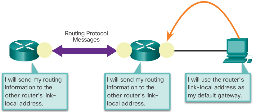
-
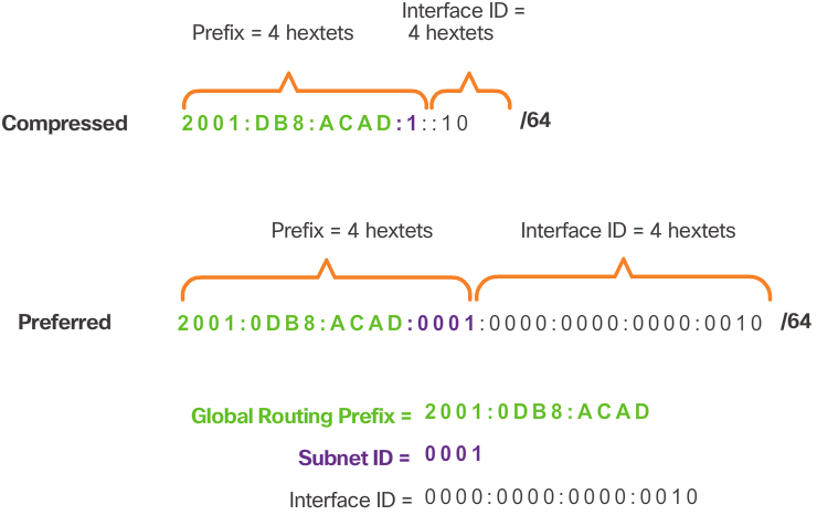
Structure of an IPv6 Global Unicast Address
- Subnet ID
- The Subnet ID is used by an organization to identify subnets within its site. The larger the subnet ID, the more subnets available.
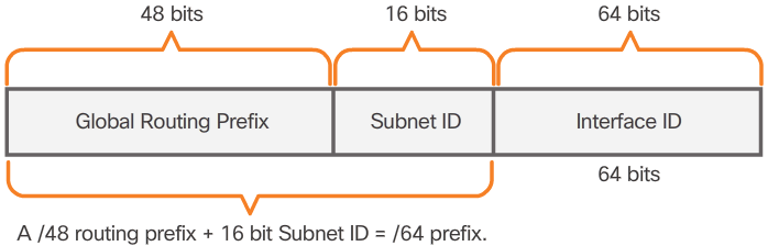
- Interface ID
- The IPv6 Interface ID is equivalent to the host portion of an IPv4 address. The term Interface ID is used because a single host may have multiple interfaces, each having one or more IPv6 addresses. It is highly recommended that in most cases /64 subnets should be used. In other words a 64-bit interface ID as shown in Figure 2.
- Note: Unlike IPv4, in IPv6, the all-0s and all-1s host addresses can be assigned to a device. The all-1s address can be used due to the fact that broadcast addresses are not used within IPv6. The all-0s address can also be used, but is reserved as a Subnet-Router anycast address, and should be assigned only to routers.
- An easy way to read most IPv6 addresses is to count the number of hextets. As shown in Figure 3, in a /64 global unicast address the first four hextets are for the network portion of the address, with the fourth hextet indicating the Subnet ID. The remaining four hextets are for the Interface ID.
Structure of an IPv6 Global Unicast Address
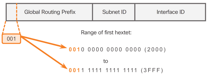
- IPv6 global unicast addresses are globally unique and routable on the IPv6 Internet. These addresses are equivalent to public IPv4 addresses. The Internet Committee for Assigned Names and Numbers (ICANN), the operator for IANA, allocates IPv6 address blocks to the five RIRs. Currently, only global unicast addresses with the first three bits of 001 or 2000::/3 are being assigned. This is only 1/8th of the total available IPv6 address space, excluding only a very small portion for other types of unicast and multicast addresses.
- Note: The 2001:0DB8::/32 address has been reserved for documentation purposes, including use in examples.
- Figure 1 shows the structure and range of a global unicast address.
- A global unicast address has three parts:
- Global routing prefix
- Subnet ID
- Interface ID
- Global Routing Prefix
- The global routing prefix is the prefix, or network, portion of the address that is assigned by the provider, such as an ISP, to a customer or site. Typically, RIRs assign a /48 global routing prefix to customers. This can include everyone from enterprise business networks to individual households.
- Figure 2 shows the structure of a global unicast address using a /48 global routing prefix. /48 prefixes are the most common global routing prefixes assigned and will be used in most of the examples throughout this course.
- For example, the IPv6 address 2001:0DB8:ACAD::/48 has a prefix that indicates that the first 48 bits (3 hextets) (2001:0DB8:ACAD) is the prefix or network portion of the address. The double colon (::) prior to the /48 prefix length means the rest of the address contains all 0s.
- The size of the global routing prefix determines the size of the subnet ID.
-
Static Configuration of a Global Unicast Address cont...
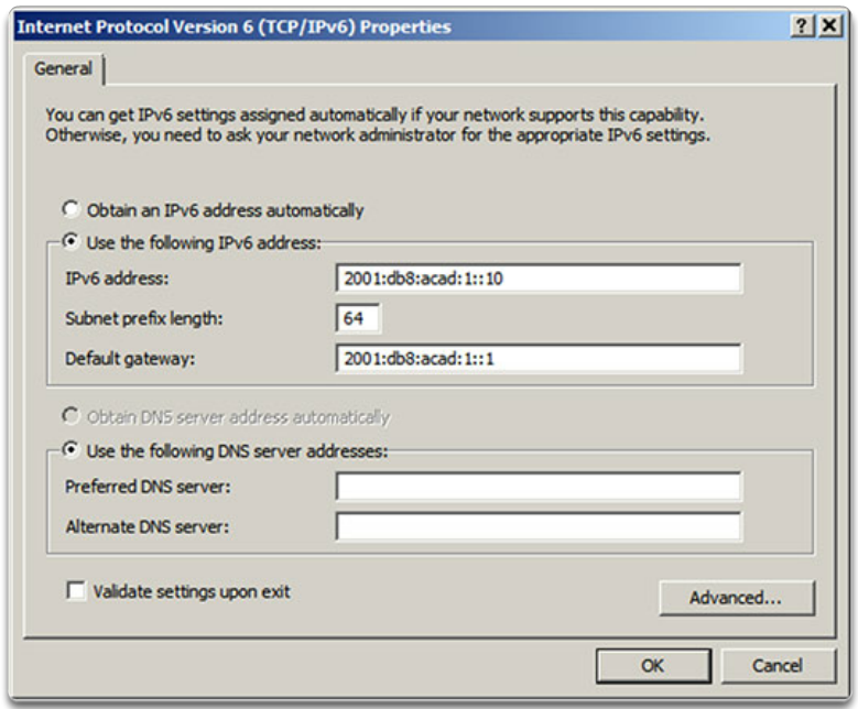
- Host Configuration
- Manually configuring the IPv6 address on a host is similar to configuring an IPv4 address.
- As shown in Figure 2, the default gateway address configured for PC1 is 2001:DB8:ACAD:1::1. This is the global unicast address of the R1 GigabitEthernet interface on the same network. Alternatively, the default gateway address can be configured to match the link-local address of the GigabitEthernet interface. Either configuration will work.
- Just as with IPv4, configuring static addresses on clients does not scale to larger environments. For this reason, most network administrators in an IPv6 network will enable dynamic assignment of IPv6 addresses.
- There are two ways in which a device can obtain an IPv6 global unicast address automatically:
- Stateless Address Autoconfiguration (SLAAC)
- DHCPv6
- Note: When DHCPv6 or SLAAC is used, the local router's link-local address will automatically be specified as the default gateway address.
Static Configuration of a Global Unicast Address
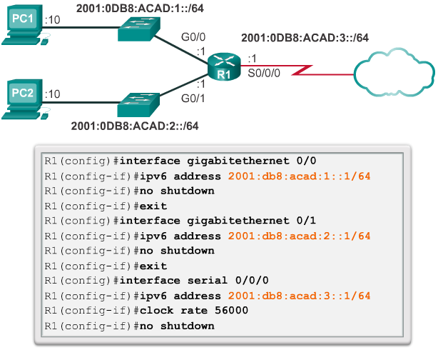
- Router Configuration
- Most IPv6 configuration and verification commands in the Cisco IOS are similar to their IPv4 counterparts. In many cases, the only difference is the use of ipv6 in place of ip within the commands.
- The command to configure an IPv6 global unicast address on an interface is ipv6 address ipv6-address/prefix-length.
- Notice that there is not a space between ipv6-address and prefix-length.
- The example configuration uses the topology shown in Figure 1 and these IPv6 subnets:
- 2001:0DB8:ACAD:0001:/64 (or 2001:DB8:ACAD:1::/64)
- 2001:0DB8:ACAD:0002:/64 (or 2001:DB8:ACAD:2::/64)
- 2001:0DB8:ACAD:0003:/64 (or 2001:DB8:ACAD:3::/64)
- Figure 1 also shows the commands required to configure the IPv6 global unicast address on the GigabitEthernet 0/0, GigabitEthernet 0/1, and Serial 0/0/0 interface of R1.
-
Dynamic Configuration - SLAAC cont....
- As shown in Figure 1, there are three options for RA messages:
- Option 1: SLAAC
- Option 2: SLAAC with a stateless DHCPv6 server
- Option 3: Stateful DHCPv6 (no SLAAC)
- RA Option 1: SLAAC
- By default, the RA message suggests that the receiving device use the information in the RA message to create its own IPv6 global unicast address and for all other information. The services of a DHCPv6 server are not required.
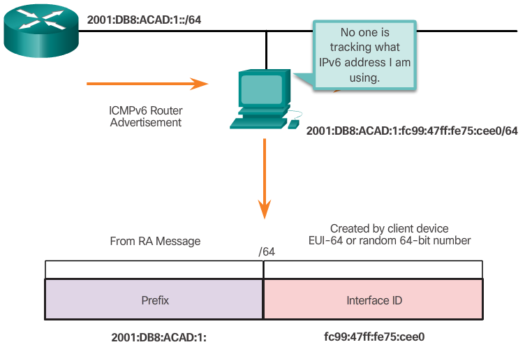
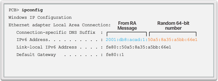
- SLAAC is stateless, which means there is no central server (for example, a stateful DHCPv6 server) allocating global unicast addresses and keeping a list of devices and their addresses. With SLAAC, the client device uses the information in the RA message to create its own global unicast address. As shown in Figure 2, the two parts of the address are created as follows:
- Prefix – Received in the RA message
- Interface ID – Uses the EUI-64 process or by generating a random 64-bit number
Dynamic Configuration – DHCPv6
- By default, the RA message is option 1, SLAAC only. The router’s interface can be configured to send a router advertisement using SLAAC and stateless DHCPv6, or stateful DHCPv6 only.
- RA Option 2: SLAAC and Stateless DHCPv6
- With this option, the RA message suggests devices use:
- SLAAC to create its own IPv6 global unicast address
- The router’s link-local address, the RA’s source IPv6 address for the default gateway address.
- A stateless DHCPv6 server to obtain other information such as a DNS server address and a domain name.
- A stateless DHCPv6 server distributes DNS server addresses and domain names. It does not allocate global unicast addresses.
- RA Option 3: Stateful DHCPv6
- Stateful DHCPv6 is similar to DHCP for IPv4. A device can automatically receive its addressing information including a global unicast address, prefix length, and the addresses of DNS servers using the services of a stateful DHCPv6 server.
- With this option the RA message suggests devices use:
- The router’s link-local address, the RA’s source IPv6 address for the default gateway address.
- A stateful DHCPv6 server to obtain a global unicast address, DNS server address, domain name and all other information.
- A stateful DHCPv6 server allocates and maintains a list of which device receives which IPv6 address. DHCP for IPv4 is stateful.
- Note: The default gateway address can only be obtained dynamically from the RA message. The stateless or stateful DHCPv6 server does not provide the default gateway address.
Dynamic Configuration - SLAAC
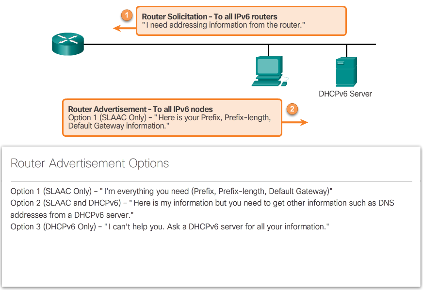
- Stateless Address Autoconfiguration (SLAAC) is a method that allows a device to obtain its prefix, prefix length, default gateway address, and other information from an IPv6 router without the use of a DHCPv6 server. Using SLAAC, devices rely on the local router’s ICMPv6 Router Advertisement (RA) messages to obtain the necessary information.
- IPv6 routers periodically send out ICMPv6 RA messages, every 200 seconds, to all IPv6-enabled devices on the network. An RA message will also be sent in response to a host sending an ICMPv6 Router Solicitation (RS) message.
- IPv6 routing is not enabled by default. To enable a router as an IPv6 router, the ipv6 unicast-routing global configuration command must be used.
- Note: IPv6 addresses can be configured on a router without it being an IPv6 router.
- The ICMPv6 RA message is a suggestion to a device on how to obtain an IPv6 global unicast address. The ultimate decision is up to the device’s operating system. The ICMPv6 RA message includes:
- Network prefix and prefix length – Tells the device which network it belongs to.
- Default gateway address – This is an IPv6 link-local address, the source IPv6 address of the RA message.
- DNS addresses and domain name – Addresses of DNS servers and a domain name.
-
EUI-64 Process and Randomly Generated cont...
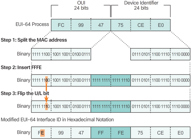
- An EUI-64 Interface ID is represented in binary and is made up of three parts:
- 24-bit OUI from the client MAC address, but the 7th bit (the Universally/Locally (U/L) bit) is reversed. This means that if the 7th bit is a 0, it becomes a 1, and vice versa.
- The inserted 16-bit value FFFE (in hexadecimal)
- 24-bit Device Identifier from the client MAC address
- The EUI-64 process is illustrated in Figure 2, using R1’s GigabitEthernet MAC address of FC99:4775:CEE0.
- Step 1: Divide the MAC address between the OUI and device identifier.
- Step 2: Insert the hexadecimal value FFFE, which in binary is: 1111 1111 1111 1110.
- Step 3: Convert the first 2 hexadecimal values of the OUI to binary and flip the U/L bit (bit 7). In this example, the 0 in bit 7 is changed to a 1.
- The result is an EUI-64 generated Interface ID of FE99:47FF:FE75:CEE0.
- Note: The use of the U/L bit, and the reasons for reversing its value, are discussed in RFC 5342.
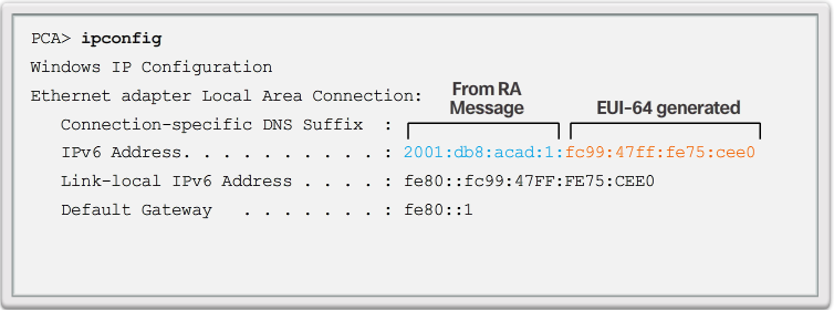
- Figure 3 shows PCA’s IPv6 global unicast address dynamically created using SLAAC and the EUI-64 process. An easy way to identify that an address was more than likely created using EUI-64 is the FFFE located in the middle of the Interface ID, as shown in Figure 3.
- The advantage of EUI-64 is the Ethernet MAC address can be used to determine the Interface ID. It also allows network administrators to easily track an IPv6 address to an end-device using the unique MAC address. However, this has caused privacy concerns among many users. They are concerned that their packets can be traced to the actual physical computer. Due to these concerns, a randomly generated Interface ID may be used instead.
- Randomly Generated Interface IDs
- Depending upon the operating system, a device may use a randomly generated Interface ID instead of using the MAC address and the EUI-64 process. For example, beginning with Windows Vista, Windows uses a randomly generated Interface ID instead of one created with EUI-64. Windows XP and previous Windows operating systems used EUI-64.
- After the Interface ID is established, either through the EUI-64 process or through random generation, it can be combined with an IPv6 prefix in the RA message to create a global unicast address, as shown in Figure 4.
- Note: To ensure the uniqueness of any IPv6 unicast address, the client may use a process known as Duplicate Address Detection (DAD). This is similar to an ARP request for its own address. If there isn’t a reply, then the address is unique.
EUI-64 Process and Randomly Generated
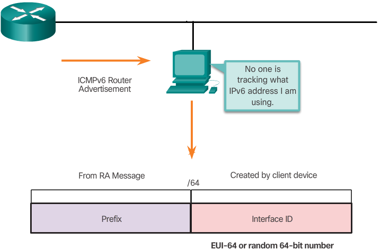
- When the RA message is either SLAAC or SLAAC with stateless DHCPv6, the client must generate its own Interface ID. The client knows the prefix portion of the address from the RA message but must create its own Interface ID. The Interface ID can be created using the EUI-64 process or a randomly generated 64-bit number, as shown in Figure 1.
- EUI-64 Process
- IEEE defined the Extended Unique Identifier (EUI) or modified EUI-64 process. This process uses a client’s 48-bit Ethernet MAC address, and inserts another 16 bits in the middle of the 48-bit MAC address to create a 64-bit Interface ID.
- Ethernet MAC addresses are usually represented in hexadecimal and are made up of two parts:
- Organizationally Unique Identifier (OUI) – The OUI is a 24-bit (6 hexadecimal digits) vendor code assigned by IEEE.
- Device Identifier – The device identifier is a unique 24-bit (6 hexadecimal digits) value within a common OUI.
-
Verifying IPv6 Address Configuration
- As shown in this 📷 figure, the command to verify the IPv6 interface configuration is similar to the command used for IPv4.
- The show interface command displays the MAC address of the Ethernet interfaces. EUI-64 uses this MAC address to generate the Interface ID for the link-local address. Additionally, the show ipv6 interface brief command displays abbreviated output for each of the interfaces. The [up/up] output on the same line as the interface indicates the Layer 1/Layer 2 interface state. This is the same as the Status and Protocol columns in the equivalent IPv4 command.
- Notice that each interface has two IPv6 addresses. The second address for each interface is the global unicast address that was configured. The first address, the one that begins with FE80, is the link-local unicast address for the interface. Recall that the link-local address is automatically added to the interface when a global unicast address is assigned.
- Also, notice that R1’s Serial 0/0/0 link-local address is the same as its GigabitEthernet 0/0 interface. Serial interfaces do not have Ethernet MAC addresses, so Cisco IOS uses the MAC address of the first available Ethernet interface. This is possible because link-local interfaces only have to be unique on that link.
- The link-local address of the router interface is typically the default gateway address for devices on that link or network.
- As shown in this 📷 figure, the show ipv6 route command can be used to verify that IPv6 networks and specific IPv6 interface addresses have been installed in the IPv6 routing table. The show ipv6 route command will only display IPv6 networks, not IPv4 networks.
- Within the route table, a C next to a route indicates that this is a directly connected network. When the router interface is configured with a global unicast address and is in the “up/up” state, the IPv6 prefix and prefix length is added to the IPv6 routing table as a connected route.
- The IPv6 global unicast address configured on the interface is also installed in the routing table as a local route. The local route has a /128 prefix. Local routes are used by the routing table to efficiently process packets with a destination address of the router’s interface address.
- The ping command for IPv6 is identical to the command used with IPv4, except that an IPv6 address is used. As shown in this 📷 figure, the command is used to verify Layer 3 connectivity between R1 and PC1. When pinging a link-local address from a router, Cisco IOS will prompt the user for the exit interface. Because the destination link-local address can be on one or more of its links or networks, the router needs to know which interface to send the ping to.
Dynamic Link-Local Addresses
- All IPv6 devices must have an IPv6 link-local address. A link-local address can be established dynamically or configured manually as a static link-local address.
- This 📷 figure shows the link-local address is dynamically created using the FE80::/10 prefix and the Interface ID using the EUI-64 process or a randomly generated 64-bit number. Operating systems will typically use the same method for both a SLAAC created global unicast address and a dynamically assigned link-local address, as shown in this 📷 figure.
- Cisco routers automatically create an IPv6 link-local address whenever a global unicast address is assigned to the interface. By default, Cisco IOS routers use EUI-64 to generate the Interface ID for all link-local address on IPv6 interfaces. For serial interfaces, the router will use the MAC address of an Ethernet interface. Recall that a link-local address must be unique only on that link or network. However, a drawback to using the dynamically assigned link-local address is its length, which makes it challenging to identify and remember assigned addresses. This 📷 figure displays the MAC address on router R1’s GigabitEthernet 0/0 interface. This address is used to dynamically create the link-local address on the same interface.
- To make it easier to recognize and remember these addresses on routers, it is common to statically configure IPv6 link-local addresses on routers.
Static Link-Local Addresses
- Configuring the link-local address manually provides the ability to create an address that is recognizable and easier to remember.
- Link-local addresses can be configured manually using the same interface command used to create IPv6 global unicast addresses but with the additional link-local parameter. When an address begins with this hextet within the range of FE80 to FEBF, the link-local parameter must follow the address.
- The 📷 figure shows the configuration of a link-local address using the ipv6 address interface command. The link-local address FE80::1 is used to make it easily recognizable as belonging to router R1. The same IPv6 link-local address is configured on all of R1’s interfaces. FE80::1 can be configured on each link because it only has to be unique on that link.
- Similar to R1, router R2 would be configured with FE80::2 as the IPv6 link-local address on all of its interfaces.
X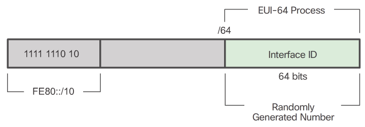 X
X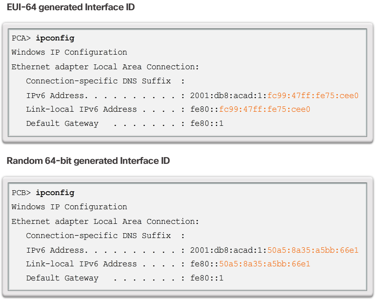 X
X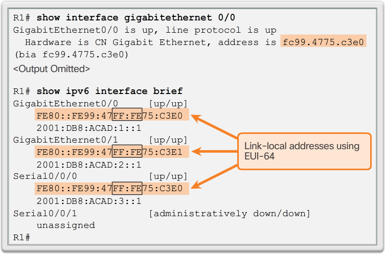 X
X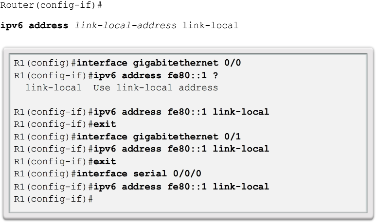 X
X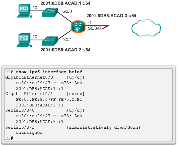 X
X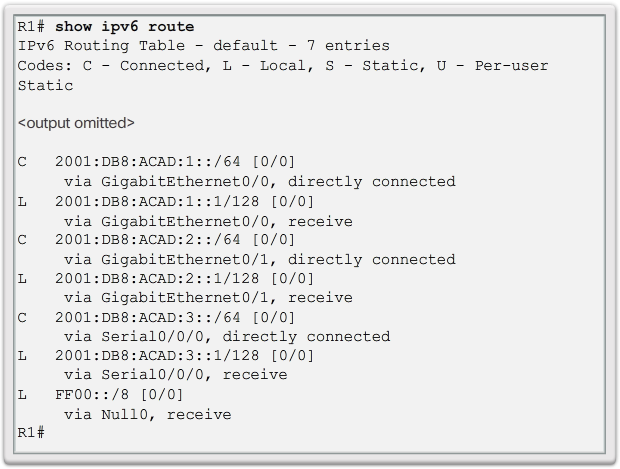 X
X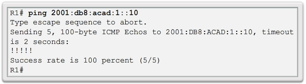
-
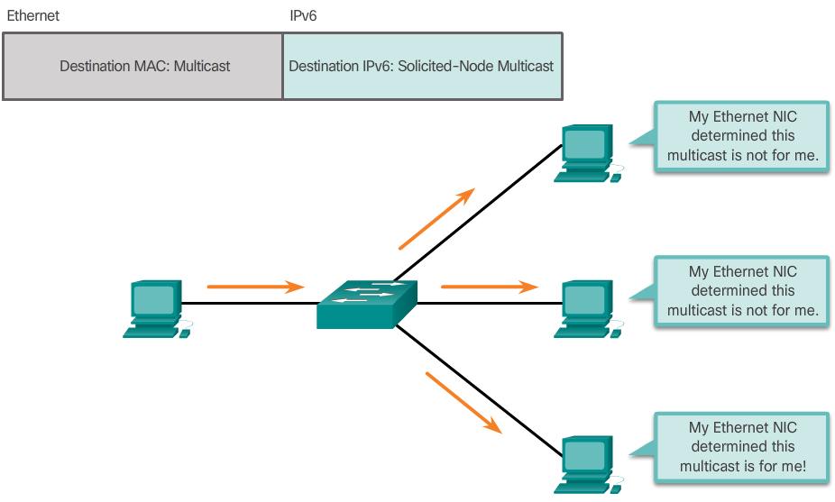
Solicited-Node IPv6 Multicast Addresses
- A solicited-node multicast address is similar to the all-nodes multicast address. The advantage of a solicited-node multicast address is that it is mapped to a special Ethernet multicast address. This allows the Ethernet NIC to filter the frame by examining the destination MAC address without sending it to the IPv6 process to see if the device is the intended target of the IPv6 packet.
Assigned IPv6 Multicast Addresses
- IPv6 multicast addresses are similar to IPv4 multicast addresses. Recall that a multicast address is used to send a single packet to one or more destinations (multicast group). IPv6 multicast addresses have the prefix FF00::/8.
- Note: Multicast addresses can only be destination addresses and not source addresses.
- There are two types of IPv6 multicast addresses:
- Assigned multicast
- Solicited node multicast
- Assigned Multicast
- Assigned multicast addresses are reserved multicast addresses for predefined groups of devices. An assigned multicast address is a single address used to reach a group of devices running a common protocol or service. Assigned multicast addresses are used in context with specific protocols such as DHCPv6.
- Two common IPv6 assigned multicast groups include:
- FF02::1 All-nodes multicast group – This is a multicast group that all IPv6-enabled devices join. A packet sent to this group is received and processed by all IPv6 interfaces on the link or network. This has the same effect as a broadcast address in IPv4. The 📷 figure shows an example of communication using the all-nodes multicast address. An IPv6 router sends Internet Control Message Protocol version 6 (ICMPv6) RA messages to the all-node multicast group. The RA message informs all IPv6-enabled devices on the network about addressing information, such as the prefix, prefix length, and default gateway.
- FF02::2 All-routers multicast group – This is a multicast group that all IPv6 routers join. A router becomes a member of this group when it is enabled as an IPv6 router with the ipv6 unicast-routing global configuration command. A packet sent to this group is received and processed by all IPv6 routers on the link or network.
- IPv6-enabled devices send ICMPv6 Router Solicitation (RS) messages to the all-routers multicast address. The RS message requests an RA message from the IPv6 router to assist the device in its address configuration.
X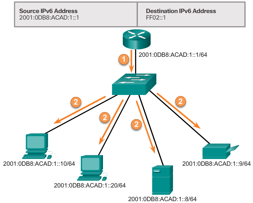
-

ICMPv6 Router Solicitation and Router Advertisement Messages
- The informational and error messages found in ICMPv6 are very similar to the control and error messages implemented by ICMPv4. However, ICMPv6 has new features and improved functionality not found in ICMPv4. ICMPv6 messages are encapsulated in IPv6.
- ICMPv6 includes four new protocols as part of the Neighbor Discovery Protocol (ND or NDP).
- Messaging between an IPv6 router and an IPv6 device:
- Router Solicitation (RS) message
- Router Advertisement (RA) message
- Messaging between IPv6 devices:
- Neighbor Solicitation message
- Neighbor Advertisement message
- The 📷 figure shows an example of a PC and router exchanging Solicitation and Router Advertisement messages. Click each message for more information.
- Neighbor Solicitation and Neighbor Advertisement messages are used for Address resolution and Duplicate Address Detection (DAD).
- Address Resolution
- Address resolution is used when a device on the LAN knows the IPv6 unicast address of a destination but does not know its Ethernet MAC address. To determine the MAC address for the destination, the device will send an NS message to the solicited node address. The message will include the known (targeted) IPv6 address. The device that has the targeted IPv6 address will respond with an NA message containing its Ethernet MAC address. The 📷 figure shows two PCs exchanging NS and NA messages. Click each message for more information.
- Duplicate Address Detection
- When a device is assigned a global unicast or link-local unicast address, it is recommended that DAD is performed on the address to ensure that it is unique. To check the uniqueness of an address, the device will send an NS message with its own IPv6 address as the targeted IPv6 address, shown in the 📷 figure. If another device on the network has this address, it will respond with an NA message. This NA message will notify the sending device that the address is in use. If a corresponding NA message is not returned within a certain period of time, the unicast address is unique and acceptable for use.
- Note: DAD is not required, but RFC 4861 recommends that DAD is performed on unicast addresses.
ICMPv4 and ICMPv6
- Although IP is not a reliable protocol, the TCP/IP suite does provide for messages to be sent in the event of certain errors. These messages are sent using the services of ICMP. The purpose of these messages is to provide feedback about issues related to the processing of IP packets under certain conditions, not to make IP reliable. ICMP messages are not required and are often not allowed within a network for security reasons.
- ICMP is available for both IPv4 and IPv6. ICMPv4 is the messaging protocol for IPv4. ICMPv6 provides these same services for IPv6 but includes additional functionality. In this course, the term ICMP will be used when referring to both ICMPv4 and ICMPv6.
- The types of ICMP messages and the reasons why they are sent, are extensive. We will discuss some of the more common messages.
- ICMP messages common to both ICMPv4 and ICMPv6 include:
- Host confirmation
- Destination or Service Unreachable
- Time exceeded
- Route redirection
- Host Confirmation
- An ICMP Echo Message can be used to determine if a host is operational. The local host sends an ICMP Echo Request to a host. If the host is available, the destination host responds with an Echo Reply. In the figure, click the Play button to see an animation of the ICMP Echo Request/Echo Reply. This use of the ICMP Echo messages is the basis of the ping utility.
- Destination or Service Unreachable
- When a host or gateway receives a packet that it cannot deliver, it can use an ICMP Destination Unreachable message to notify the source that the destination or service is unreachable. The message will include a code that indicates why the packet could not be delivered.
- Some of the Destination Unreachable codes for ICMPv4 are:
- 0 - Net unreachable
- 1 - Host unreachable
- 2 - Protocol unreachable
- 3 - Port unreachable
- Note: ICMPv6 has similar but slightly different codes for Destination Unreachable messages.
- Time Exceeded
- An ICMPv4 Time Exceeded message is used by a router to indicate that a packet cannot be forwarded because the Time to Live (TTL) field of the packet was decremented to 0. If a router receives a packet and decrements the TTL field in the IPv4 packet to zero, it discards the packet and sends a Time Exceeded message to the source host.
- ICMPv6 also sends a Time Exceeded message if the router cannot forward an IPv6 packet because the packet has expired. IPv6 does not have a TTL field; it uses the hop limit field to determine if the packet has expired.
X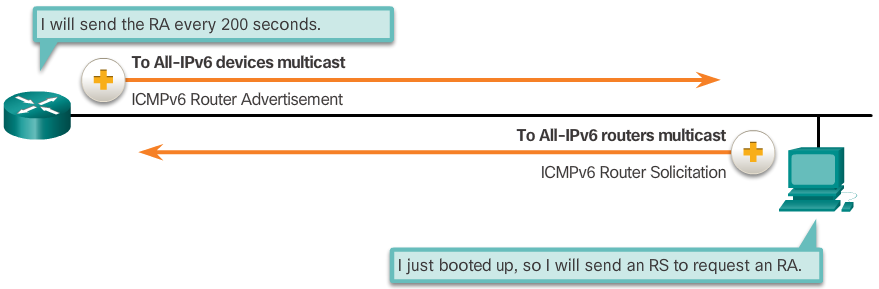 X
X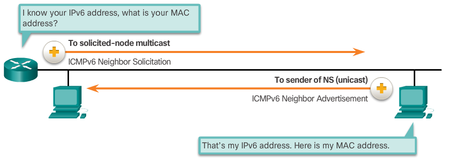 X
X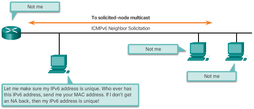
-
Ping – Testing Connectivity to Remote
- Ping can also be used to test the ability of a local host to communicate across an internetwork. The local host can ping an operational IPv4 host of a remote network, as shown in the 📷 figure.
- If this ping is successful, the operation of a large piece of the internetwork can be verified. A successful ping across the internetwork confirms communication on the local network, the operation of the router serving as the gateway, and the operation of all other routers that might be in the path between the local network and the network of the remote host.
- Additionally, the functionality of the remote host can be verified. If the remote host could not communicate outside of its local network, it would not have responded.
- Note: Many network administrators limit or prohibit the entry of ICMP messages into the corporate network; therefore, the lack of a ping response could be due to security restrictions.
Traceroute – Testing the Path
- Ping is used to test connectivity between two hosts but does not provide information about the details of devices between the hosts. Traceroute (tracert) is a utility that generates a list of hops that were successfully reached along the path. This list can provide important verification and troubleshooting information. If the data reaches the destination, then the trace lists the interface of every router in the path between the hosts. If the data fails at some hop along the way, the address of the last router that responded to the trace can provide an indication of where the problem or security restrictions are found.
- Round Trip Time (RTT)
- Using traceroute provides round trip time for each hop along the path and indicates if a hop fails to respond. The round trip time is the time a packet takes to reach the remote host and for the response from the host to return. An asterisk (*) is used to indicate a lost or unreplied packet.
- This information can be used to locate a problematic router in the path. If the display shows high response times or data losses from a particular hop, this is an indication that the resources of the router or its connections may be stressed.
- IPv4 TTL and IPv6 Hop Limit
- Traceroute makes use of a function of the TTL field in IPv4 and the Hop Limit field in IPv6 in the Layer 3 headers, along with the ICMP time exceeded message.
- The first sequence of messages sent from traceroute will have a TTL field value of 1. This causes the TTL to time out the IPv4 packet at the first router. This router then responds with an ICMPv4 message. Traceroute now has the address of the first hop.
- Traceroute then progressively increments the TTL field (2, 3, 4...) for each sequence of messages. This provides the trace with the address of each hop as the packets timeout further down the path. The TTL field continues to be increased until the destination is reached, or it is incremented to a predefined maximum.
- After the final destination is reached, the host responds with either an ICMP port unreachable message or an ICMP echo reply message instead of the ICMP time exceeded message.
Ping - Testing the Local Stack
- Ping is a testing utility that uses ICMP echo request and echo reply messages to test connectivity between hosts. Ping works with both IPv4 and IPv6 hosts.
- To test connectivity to another host on a network, an echo request is sent to the host address using the ping command. If the host at the specified address receives the echo request, it responds with an echo reply. As each echo reply is received, ping provides feedback on the time between when the request was sent and when the reply was received. This can be a measure of network performance.
- Ping has a timeout value for the reply. If a reply is not received within the timeout, ping provides a message indicating that a response was not received. This usually indicates that there is a problem, but could also indicate that security features blocking ping messages have been enabled on the network.
- After all the requests are sent, the ping utility provides a summary that includes the success rate and average round-trip time to the destination.
- Pinging the Local Loopback
- There are some special testing and verification cases for which we can use ping. One case is for testing the internal configuration of IPv4 or IPv6 on the local host. To perform this test, we ping the local loopback address of 127.0.0.1 for IPv4 (::1 for IPv6). Testing the IPv4 loopback is shown in the 📷 figure.
- A response from 127.0.0.1 for IPv4, or ::1 for IPv6, indicates that IP is properly installed on the host. This response comes from the network layer. This response is not, however, an indication that the addresses, masks, or gateways are properly configured. Nor does it indicate anything about the status of the lower layer of the network stack. This simply tests IP down through the network layer of IP. An error message indicates that TCP/IP is not operational on the host.
Ping – Testing Connectivity to the Local LAN
- You can also use ping to test the ability of a host to communicate on the local network. This is generally done by pinging the IP address of the gateway of the host. A ping to the gateway indicates that the host and the router interface serving as the gateway are both operational on the local network.
- For this test, the gateway address is most often used because the router is normally always operational. If the gateway address does not respond, a ping can be sent to the IP address of another host on the local network that is known to be operational.
- If either the gateway or another host responds, then the local host can successfully communicate over the local network. If the gateway does not respond but another host does, this could indicate a problem with the router interface serving as the gateway.
- One possibility is that the wrong gateway address has been configured on the host. Another possibility is that the router interface may be fully operational but have security applied to it that prevents it from processing or responding to ping requests.
X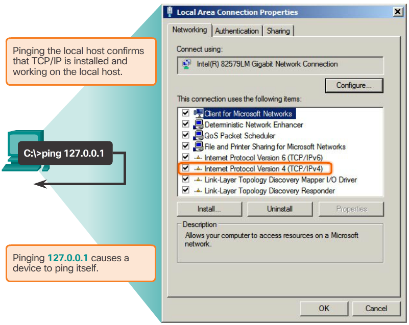 X
X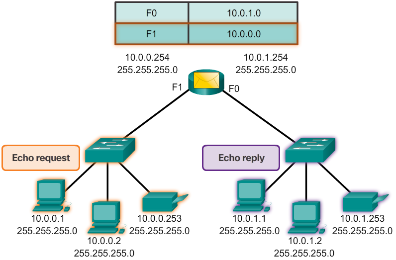
-
Summary
- IP addresses are hierarchical with network, subnetwork, and host portions.
- An IP address can represent a complete network, a specific host, or the broadcast address of the network.
- The subnet mask or prefix is used to determine the network portion of an IP address. Once implemented, an IP network needs to be tested to verify its connectivity and operational performance.
- DHCP enables the automatic assignment of addressing information such as IP address, subnet mask, default gateway, and other configuration information.
- IPv4 hosts can communicate one of three different ways: unicast, broadcast, and multicast.
- The private IPv4 address blocks are: 10.0.0.0/8, 172.16.0.0/12, and 192.168.0.0/16.
- The depletion of IPv4 address space is the motivating factor for moving to IPv6.
- Each IPv6 address has 128 bits verses the 32 bits in an IPv4 address.
- The prefix length is used to indicate the network portion of an IPv6 address using the following format: IPv6 address/prefix length.
- There are three types of IPv6 addresses: unicast, multicast, and anycast.
- An IPv6 link-local address enables a device to communicate with other IPv6-enabled devices on the same link and only on that link (subnet).
- Packets with a source or destination link-local address cannot be routed beyond the link from where the packet originated.
- IPv6 link-local addresses are in the FE80::/10 range.
- ICMP is available for both IPv4 and IPv6.