08
-

Chapter 8: Objectives
- Upon completion of this chapter, you will be able to:
- Explain why routing is necessary for hosts on different networks to communicate.
- Describe IP as a communication protocol used to identify a single device on a network.
- Given a network and a subnet mask, calculate the number of host addresses available.
- Calculate the necessary subnet mask in order to accommodate the requirements of a network.
- Describe the benefits of variable length subnet masking (VLSM).
- Explain how IPv6 address assignments are implemented in a business network.
Chapter 8
- Subnetting an IPv4 Network
- Addressing Schemes
- Design Considerations for IPv6
- Summary
-

Octet Boundaries
- Every interface on a router is connected to a network. The IP address and subnet mask configured on the router interface are used to identify the specific broadcast domain. Recall that the prefix length and the subnet mask are different ways of identifying the network portion of an address.
- IPv4 subnets are created by using one or more of the host bits as network bits. This is done by extending the subnet mask to borrow some of the bits from the host portion of the address to create additional network bits. The more host bits that are borrowed, the more subnets that can be defined.
- Networks are most easily subnetted at the octet boundary of /8, /16, and /24. The table in the 📷 figure identifies these prefix lengths, equivalent subnet masks, the network and host bits, and the number of hosts each subnet can connect. Notice that using longer prefix lengths decreases the number of hosts per subnet.
Subnetting on the Octet Boundary
- To understand how subnetting on the octet boundary can be useful, consider the following example. Assume an enterprise has chosen the private address 10.0.0.0/8 as its internal network address. That network address can connect 16,777,214 hosts in one broadcast domain. Obviously, this is not ideal.
- The enterprise could further subnet the 10.0.0.0/8 address at the octet boundary of /16 as shown in the 📷 figure. This would provide the enterprise the ability to define up to 256 subnets (i.e., 10.0.0.0/16 – 10.255.0.0/16) with each subnet capable of connecting 65,534 hosts. Notice how the first two octets identify the network portion of the address while the last two octets are for host IP addresses.
- Alternatively, the enterprise could choose to subnet at the /24 octet boundary as shown in the 📷 figure. This would enable the enterprise to define 65,536 subnets each capable of connecting 254 hosts. The /24 boundary is very popular in subnetting because it accommodates a reasonable number of hosts and conveniently subnets at the octet boundary.
Reasons for Subnetting
- Subnetting reduces overall network traffic and improves network performance. It also enables an administrator to implement security policies such as which subnets are allowed or not allowed to communicate together.
- There are various ways of using subnets to help manage network devices. Network administrators can group devices and services into subnets that are determined by:
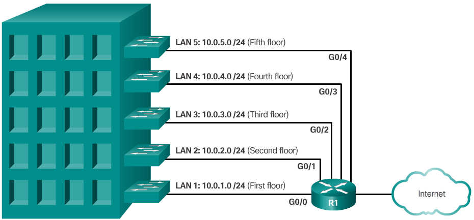
- Location, such as floors in a building (Figure 1)
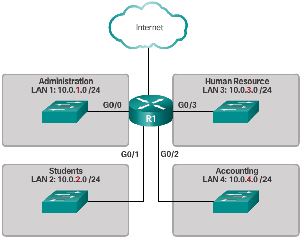
- Organizational unit (Figure 2)
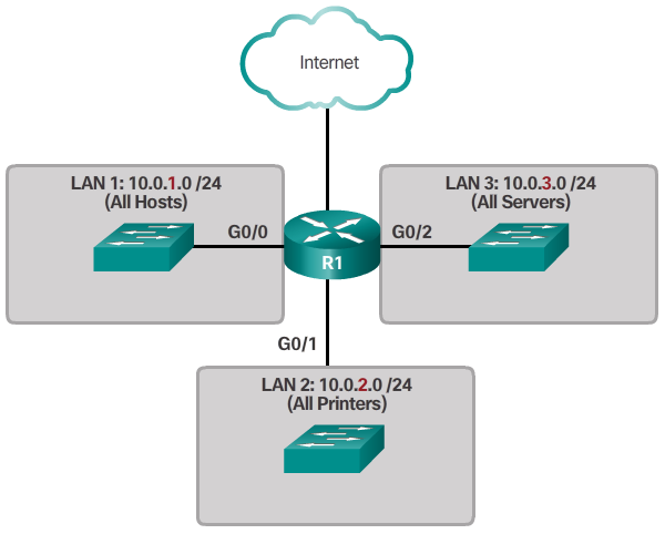
- Device type (Figure 3)
- Any other division that makes sense for the network.
- Notice in each figure, the subnets use longer prefix lengths to identify networks.
- This chapter describes how subnetting is performed. Understanding how to subnet networks is a fundamental skill that all network administrators must develop. Various methods have been developed to help understand this process. This chapter will focus on looking at the binary method. Although a little overwhelming at first, focus and pay close attention to the detail and with practice, subnetting should become easier.
X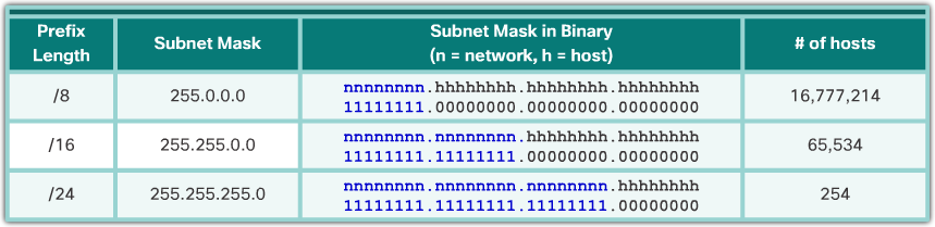 X
X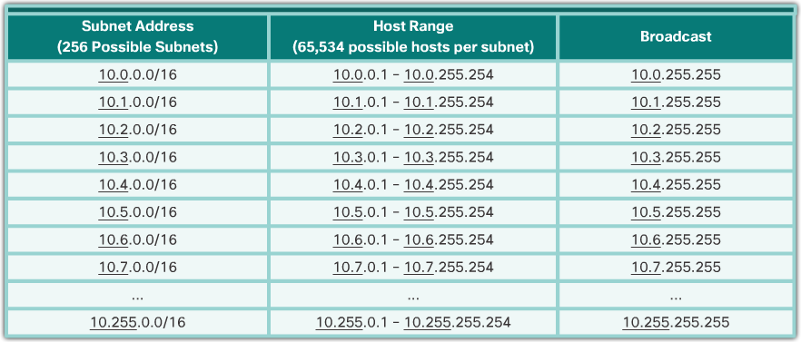 X
X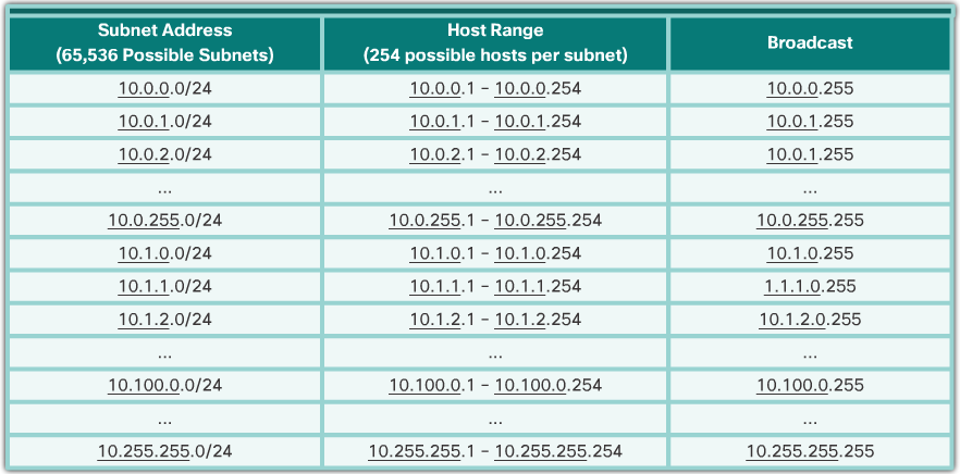
-
Classless Subnetting Example cont...
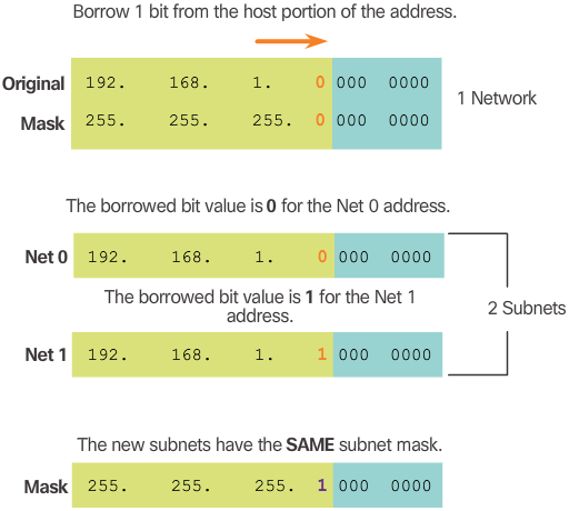
- Figure 4 displays the resulting subnet mask for both networks. Notice how it uses a 1 in the borrowed bit position to indicate that this bit is now part of the network portion.
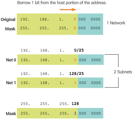
- Figure 5 displays the dotted decimal representation of the two subnet addresses and their common subnet mask. Because one bit has been borrowed, the subnet mask for each subnet is 255.255.255.128 or /25.
Classless Subnetting
- The examples seen so far borrowed host bits from the common /8, /16, and /24 network prefixes. However, subnets can borrow bits from any host bit position to create other masks.
- For instance, a /24 network address is commonly subnetted using longer prefix lengths by borrowing bits from the fourth octet. This provides the administrator with additional flexibility when assigning network addresses to a smaller number of end devices.
- As shown in the 📷 figure:
- /25 row - Borrowing 1 bit from the fourth octet creates 2 subnets supporting 126 hosts each.
- /26 row - Borrowing 2 bits creates 4 subnets supporting 62 hosts each.
- /27 row – Borrowing 3 bits creates 8 subnets supporting 30 hosts each.
- /28 row – Borrowing 4 bits creates 16 subnets supporting 14 hosts each.
- /29 row – Borrowing 5 bits creates 32 subnets supporting 6 hosts each.
- /30 row – Borrowing 6 bits creates 64 subnets supporting 2 hosts each.
- For each bit borrowed in the fourth octet, the number of subnetworks available is doubled while reducing the number of host addresses per subnet.
Classless Subnetting Example
- To understand how subnetting at a classless level can be useful, consider the following examples.
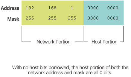
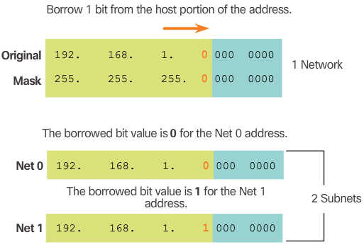
- Consider the private network address 192.168.1.0/24 shown in Figure 1. The first three octets are displayed in decimal, while the last octet is displayed in binary. The reason for this is because we will be borrowing bits from the last octet to create subnets of the 192.168.1.0/24 network.
- The subnet mask is 255.255.255.0 as indicated by the /24 prefix length. This identifies the first three octets as the network portion and the remaining 8 bits in the last octet as the host portion. Without subnetting, this network supports a single LAN interface providing 254 host IP addresses. If an additional LAN is needed, the network would need to be subnetted.
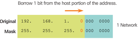
- In Figure 2, 1 bit is borrowed from the most significant bit (leftmost bit) in the host portion, thus extending the network portion to 25 bits or /25. This enables the creation of two subnets.
- Figure 3 displays the two subnets: 192.168.1.0/25 and 192.168.1.128/25. The two subnets are derived from changing the value of the bit borrowed to either 0 or 1. Because the bit borrowed is the 128 bit, the decimal value of the fourth octet for the 2nd subnet is 128.
X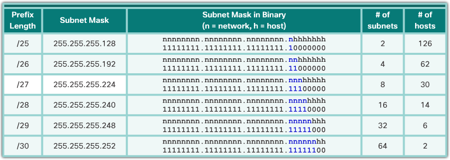
-
Creating 2 Subnets
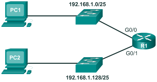
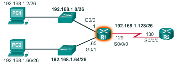
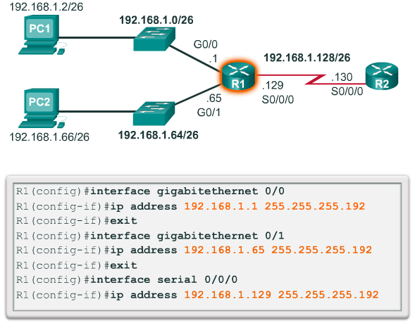
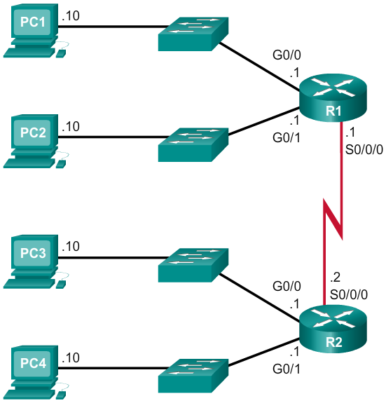
- To see how a /25 subnet is applied in a network; consider the topology in Figure 1. R1 has two LAN segments attached to its GigabitEthernet interfaces. Each LAN is assigned one of the subnets.
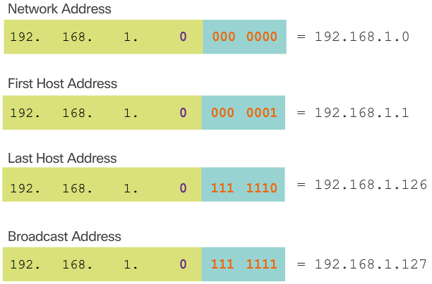
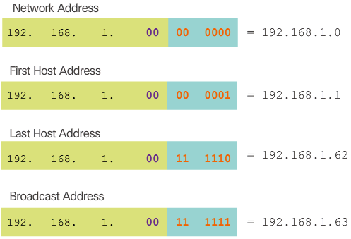
- Figure 2 displays the important addresses of the first subnet, 192.168.1.0/25. Notice how the:
- Network address is 192.168.1.0 and contains all 0 bits in the host portion of the address.
- First host address is 192.168.1.1 and contains all 0 bits plus a right-most 1 bit in the host portion of the address.
- Last host address is 192.168.1.126 and contains all 1 bits plus a right-most 0 bit in the host portion of the address.
- Broadcast address is 192.168.1.127 and contains all 1 bits in the host portion of the address.
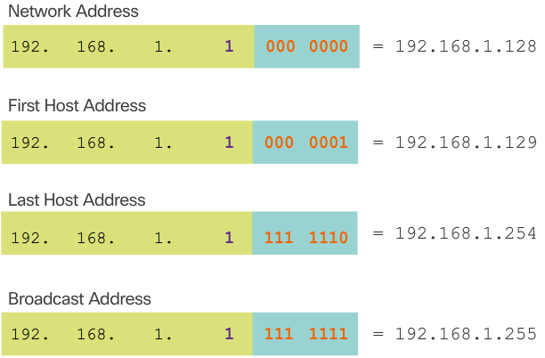
- Figure 3 displays the important addresses of the second subnet, 192.168.1.128/25.
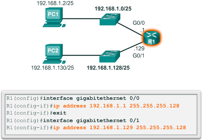
- Router interfaces must be assigned an IP address within the valid host range for the assigned subnet. This is the address that hosts on that network will use as their default gateway. A very common practice is to use the first or last available address in a network range for the router interface address. Figure 4 shows the configuration for R1’s interfaces with the first IP address for their respective subnets using the ip address interface configuration command.
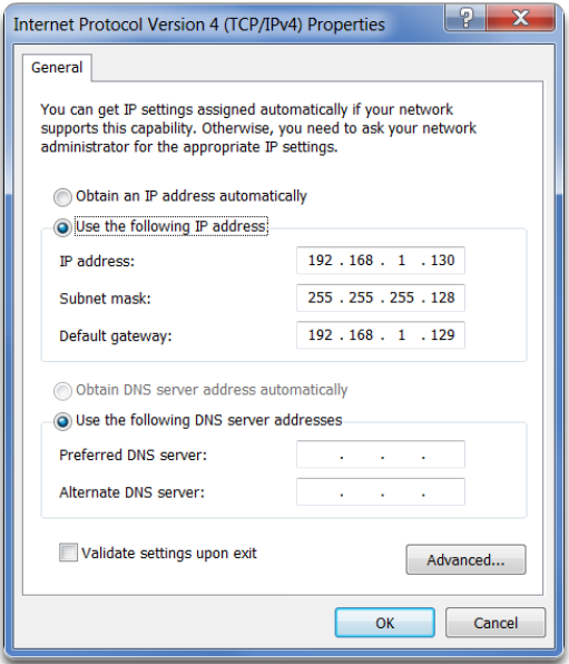
- Hosts on each subnet must be configured with an IP address and default gateway. Figure 5 displays the IP configuration for PC2 host on the 192.168.1.128/25 network. Notice that the default gateway IP address is the address configured on the G0/1 interface of R1, 192.168.1.129, and the subnet mask is 255.255.255.128.
-
Creating 4 Subnets
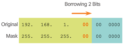
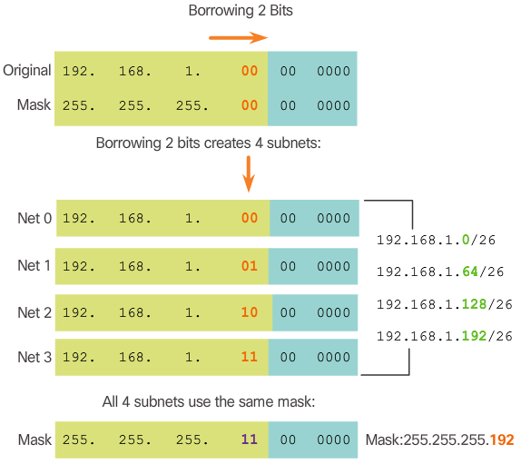
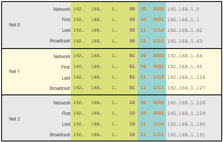
- Now consider the network topology shown in Figure 1. The enterprise is using the private network address 192.168.1.0/24 range and requires three subnets. Borrowing a single bit only provided 2 subnets; therefore, another host bit must be borrowed as shown in Figure 2. Using the 2^n formula for two borrowed bits results in 2^2 = 4 subnets. The specifics of the four subnets are shown in Figure 3. The resulting subnet mask of /26 or 255.255.255.192 is used by all four subnets.
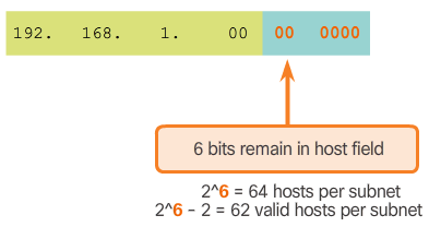
- To calculate the number of hosts, examine the last octet as shown in Figure 4. After borrowing 2 bits for the subnet, there are 6 host bits remaining. Apply the host calculation formula 2^n - 2 as shown to reveal that each subnet can support 62 host addresses. The significant addresses of the first subnet (i.e., Net 0) are displayed in Figure 5.
- Only the first three subnets are required because there are only three interfaces. Figure 6 displays the specifics of the first three subnets that will be used to satisfy the topology in Figure 1.
- Finally, Figure 7 applies the first valid host address from each subnet to the respective R1 LAN interface.
Subnetting Formulas
- "
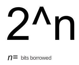
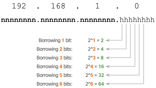
- To calculate the number of subnets that can be created from the bits borrowed, use the formula displayed in Figure 1. Figure 2 displays the possible number of subnets that can be created when borrowing 1, 2, 3, 4, 5, or 6 bits.
- Note: The last two bits cannot be borrowed from the last octet because there would be no host addresses available. Therefore, the longest prefix length possible when subnetting is /30 or 255.255.255.252.
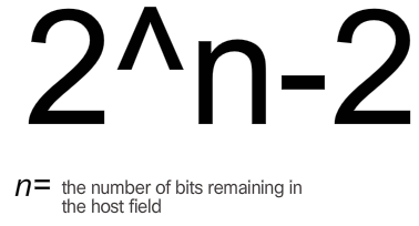
- To calculate the number of hosts that can be supported, use the formula displayed in Figure 3. There are two subnet addresses that cannot be assigned to a host, the network address and the broadcast address, so we must subtract 2.
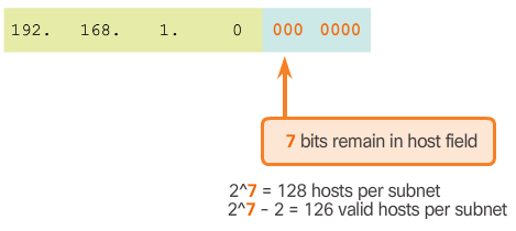
- As shown in Figure 4, there are 7 host bits remaining, so the calculation is 2^7 = 128-2 = 126. This means that each of the subnets has 126 valid host addresses.
- Therefore, borrowing 1 host bit toward the network results in creating 2 subnets, and each subnet can have a total of 126 hosts assigned.
-
Network Requirement Example cont...
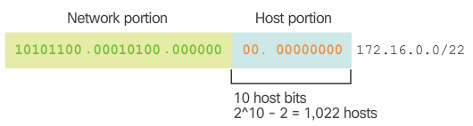
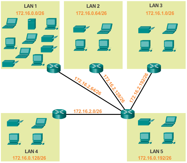
- The 172.16.0.0/22 network address has 10 host bits as shown in Figure 3. Because the largest subnet requires 40 hosts, a minimum of 6 host bits are needed to provide addressing for 40 hosts. This is determined by using this formula: 2^6 – 2 = 62 hosts.
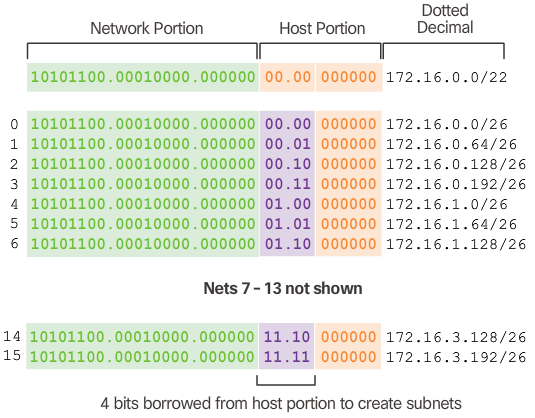
- Using the formula for determining subnets, results in 16 subnets: 2^4 = 16. Because the example internetwork requires 9 subnets this will meet the requirement and allow for some additional growth.
- Therefore, the first 4 host bits can be used to allocate subnets, as shown in Figure 4. When 4 bits are borrowed, the new prefix length is /26 with a subnet mask of 255.255.255.192.
- As shown in Figure 5, the subnets can be assigned to the LAN segments and router-to-router connections.
- This topic concludes with four activities to practice subnetting. The Chapter Appendix includes additional practice activities.
Subnetting Based on Host Requirements
- There are two considerations when planning subnets:
- the number of host addresses required for each network
- the number of individual subnets needed
- The table in the 📷 figure displays the specifics for subnetting a /24 network. Notice how there is an inverse relationship between the number of subnets and the number of hosts. The more bits borrowed to create subnets, the fewer host bits available. If more host addresses are needed, more host bits are required, resulting in fewer subnets.
- The number of host addresses required in the largest subnet will determine how many bits must be left in the host portion. Recall that two of the addresses cannot be used, so the usable number of addresses can be calculated as 2^n-2.
Subnetting Based on Network Requirements
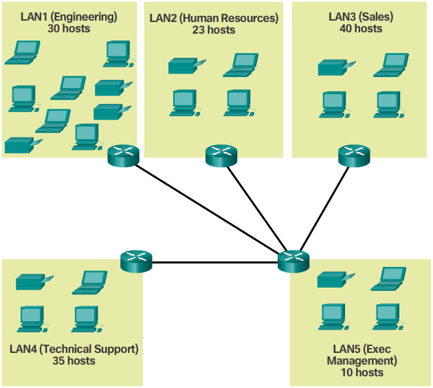
- Sometimes a certain number of subnets is required, with less emphasis on the number of host addresses per subnet. This may be the case if an organization chooses to separate their network traffic based on internal structure or department setup, as shown in the 📷 figure. For example, an organization may choose to put all host devices used by employees in the Engineering department in one network, and all host devices used by management in a separate network. In this case, the number of subnets is most important in determining how many bits to borrow.
- Recall the number of subnets created when bits are borrowed can be calculated using the formula 2^n (where n is the number of bits borrowed). The key is to balance the number of subnets needed and the number of hosts required for the largest subnet. The more bits borrowed to create additional subnets means fewer hosts available per subnet.
Network Requirement Example
- Network administrators must devise the network addressing scheme to accommodate the maximum number of hosts for each network and the number of subnets. The addressing scheme should allow for growth in the both the number of host addresses per subnet and the total number of subnets.
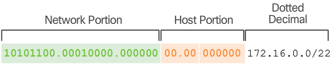
- In this example, corporate headquarters has allocated a private network address of 172.16.0.0/22 (10 host bits) to a branch location. As shown in Figure 1, this will provide 1,022 host addresses.
- The topology for the branch locations, shown in Figure 2, consists of 5 LAN segments and 4 internetwork connections between routers. Therefore, 9 subnets are required. The largest subnet requires 40 hosts.
X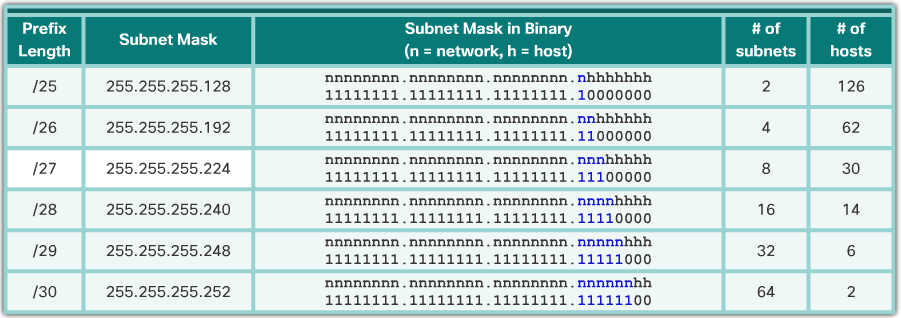 X
X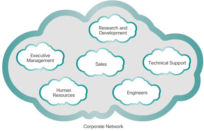
-
Basic VLSM
- To better understand the VLSM process, go back to the previous example, shown in the 📷 figure. The network 192.168.20.0/24 was subnetted into eight equal-sized subnets. Seven of the eight subnets were allocated. Four subnets were used for the LANs and three subnets for the WAN connections between the routers. Recall that the wasted address space was in the subnets used for the WAN connections, because those subnets required only two usable addresses: one for each router interface. To avoid this waste, VLSM can be used to create smaller subnets for the WAN connections.
- To create smaller subnets for the WAN links, one of the subnets will be divided. In this example, the last subnet, 192.168.20.224/27, will be further subnetted.
- Recall that when the number of needed host addresses is known, the formula 2^n-2 (where n equals the number of host bits remaining) can be used. To provide two usable addresses, 2 host bits must be left in the host portion.
- Because there are 5 host bits in the subnetted 192.168.20.224/27 address space, 3 more bits can be borrowed, leaving 2 bits in the host portion, as shown in the 📷 figure. The calculations at this point are exactly the same as those used for traditional subnetting. The bits are borrowed, and the subnet ranges are determined.
- This VLSM subnetting scheme reduces the number of addresses per subnet to a size appropriate for the WANs. Subnetting subnet 7 for WANs, allows subnets 4, 5, and 6 to be available for future networks, as well as 5 additional subnets available for WANs.
Traditional Subnetting Wastes Addresses
- Using traditional subnetting, the same number of addresses is allocated for each subnet. If all the subnets have the same requirements for the number of hosts, these fixed size address blocks would be efficient. However, most often that is not the case.
- For example, the topology shown in the 📷 figure requires seven subnets, one for each of the four LANs, and one for each of the three WAN connections between routers. Using traditional subnetting with the given address of 192.168.20.0/24, 3 bits can be borrowed from the host portion in the last octet to meet the subnet requirement of seven subnets. As shown in the 📷 figure, borrowing 3 bits creates 8 subnets and leaves 5 host bits with 30 usable hosts per subnet. This scheme creates the needed subnets and meets the host requirement of the largest LAN.
- Although this traditional subnetting meets the needs of the largest LAN and divides the address space into an adequate number of subnets, it results in significant waste of unused addresses.
- For example, only two addresses are needed in each subnet for the three WAN links. Because each subnet has 30 usable addresses, there are 28 unused addresses in each of these subnets. As shown in the 📷 figure, this results in 84 unused addresses (28x3).
- Further, this limits future growth by reducing the total number of subnets available. This inefficient use of addresses is characteristic of traditional subnetting. Applying a traditional subnetting scheme to this scenario is not very efficient and is wasteful.
- Subnetting a subnet, or using Variable Length Subnet Mask (VLSM), was designed to avoid wasting addresses.
Variable Length Subnet Masks
- In all of the previous examples of subnetting, notice that the same subnet mask was applied for all the subnets. This means that each subnet has the same number of available host addresses.
- As illustrated in the 📷 figure, traditional subnetting creates subnets of equal size. Each subnet in a traditional scheme uses the same subnet mask. As shown in the 📷 figure, VLSM allows a network space to be divided into unequal parts. With VLSM, the subnet mask will vary depending on how many bits have been borrowed for a particular subnet, thus the “variable” part of the VLSM.
- VLSM subnetting is similar to traditional subnetting in that bits are borrowed to create subnets. The formulas to calculate the number of hosts per subnet and the number of subnets created still apply.
- The difference is that subnetting is not a single pass activity. With VLSM, the network is first subnetted, and then the subnets are subnetted again. This process can be repeated multiple times to create subnets of various sizes.
- Note: When using VLSM, always begin by satisfying the host requirements of the largest subnet. Continue subnetting until the host requirements of the smallest subnet are satisfied.
X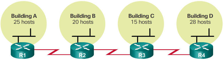 X
X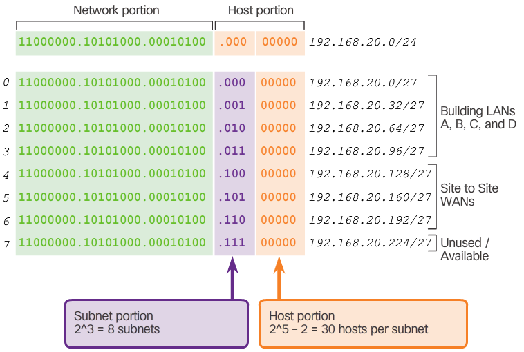 X
X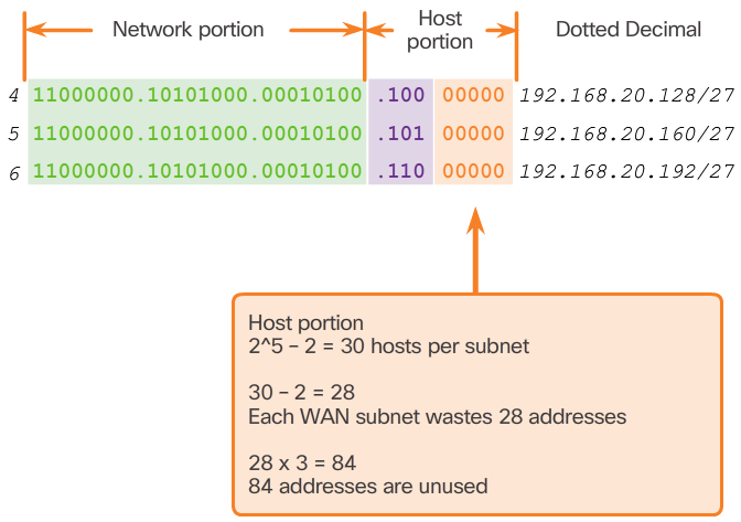 X
X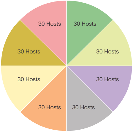 X
X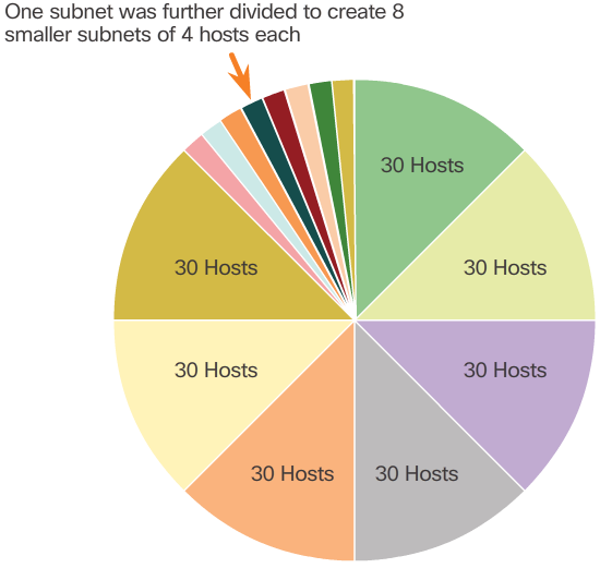 X
X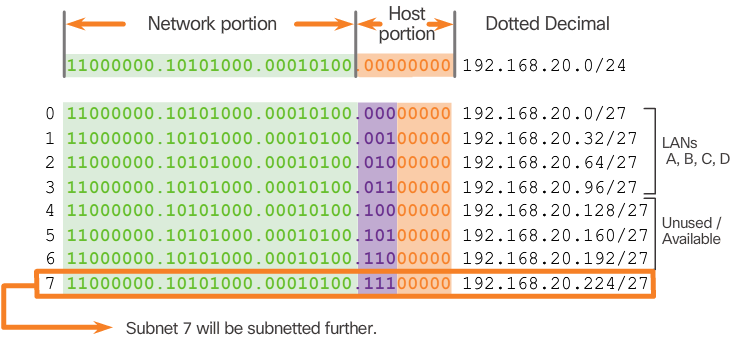 X
X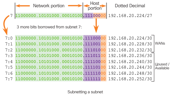
-
VLSM Chart
- An addressing chart can be used to identify which blocks of addresses are available for use and which ones are already assigned, as shown in the 📷 figure. This method helps to prevent assigning addresses that have already been allocated.
- In order to use the address space more efficiently, /30 subnets are created for WAN links, as shown in the VLSM chart in the 📷 figure. To keep the unused blocks of addresses together in a block of contiguous address space, the last /27 subnet was further subnetted to create the /30 subnets. The first 3 subnets were assigned to WAN links.
- Designing the addressing scheme in this way leaves 3 unused, contiguous /27 subnets and 5 unused contiguous /30 subnets.
VLSM in Practice
- Using the VLSM subnets, the LAN and WAN segments can be addressed without unnecessary waste.
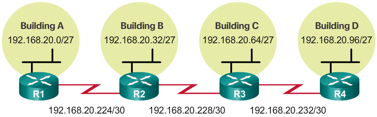
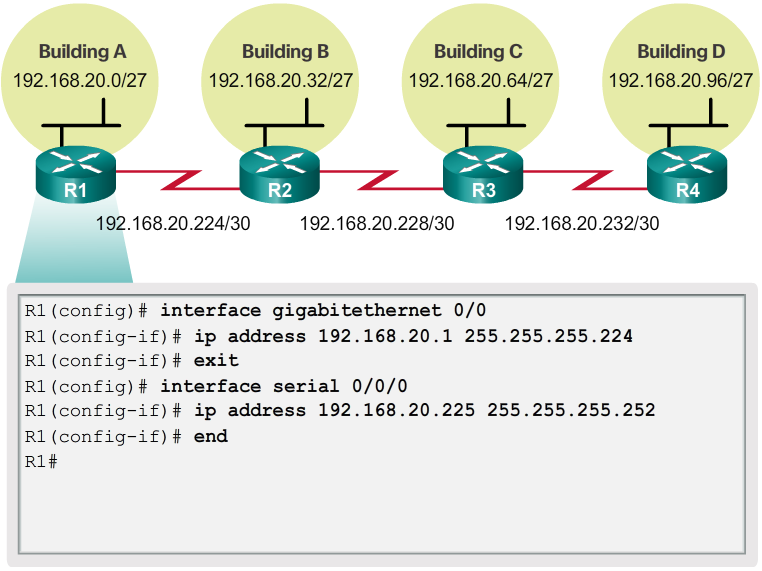
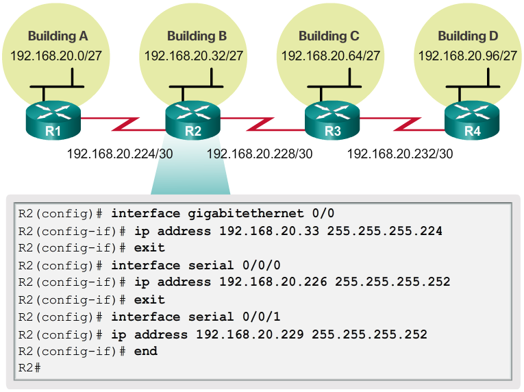
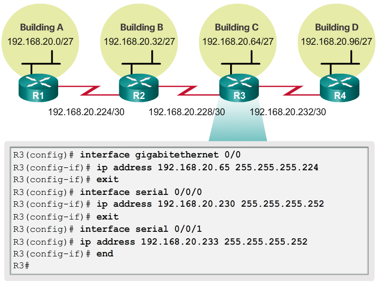
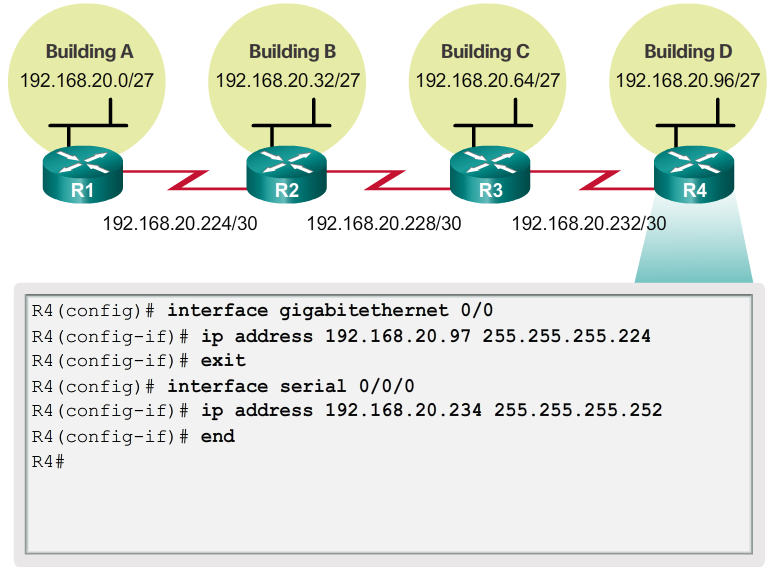
- As shown in Figure 1, the hosts in each of the LANs will be assigned a valid host address with the range for that subnet and /27 mask. Each of the four routers will have a LAN interface with a /27 subnet and a one or more serial interfaces with a /30 subnet.
- Using a common addressing scheme, the first host IPv4 address for each subnet is assigned to the LAN interface of the router. The WAN interfaces of the routers are assigned the IP addresses and mask for the /30 subnets.
- Figures 2 - 5 show the interface configuration for each of the routers.
- Hosts on each subnet will have a host IPv4 address from the range of host addresses for that subnet and an appropriate mask. Hosts will use the address of the attached router LAN interface as the default gateway address.
- Default gateway for Building A hosts (192.168.20.0/27) will be 192.168.20.1.
- Default gateway for Building B hosts (192.168.20.32/27) will be 192.168.20.33.
- Default gateway for Building C hosts (192.168.20.64/27) will be 192.168.20.65.
- Default gateway for Building D hosts (192.168.20.96/27) will be 192.168.20.97.
X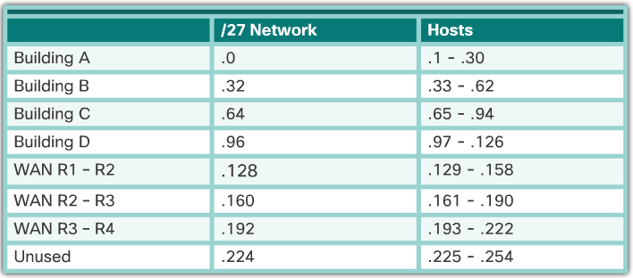 X
X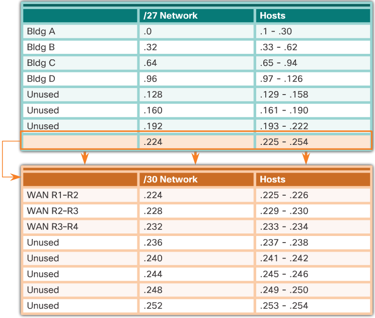
-

Planning to Address the Network
- Three primary considerations for planning address allocation are displayed in the 📷 figure.
- Preventing the duplication of addresses refers to the fact that each host in an internetwork must have a unique address. Without the proper planning and documentation, an address could be assigned to more than one host, resulting in access issues for both hosts.
- Providing and controlling access refers to the fact that some hosts, such as servers, provide resources to internal hosts as well as to external hosts. The Layer 3 address assigned to a server can be used to control access to that server. If, however, the address is randomly assigned and not well documented, controlling access is more difficult.
- Monitoring security and performance of hosts means network traffic is examined for source IP addresses that are generating or receiving excessive packets. If there is proper planning and documentation of the network addressing, problematic network devices should easily be found.
Network Address Planning
- As shown in the 📷 figure, the allocation of network layer address space within the corporate network needs to be well designed. Address assignment should not be random.
- Planning network subnets requires examination of both the needs of an organization’s network usage, and how the subnets will be structured. Performing a network requirement study is the starting point. This means looking at the entire network and determining the main sections of the network and how they will be segmented. The address plan includes determining the needs of each subnet in terms of size, how many hosts per subnet, how host addresses will be assigned, which hosts will require static IP addresses, and which hosts can use DHCP for obtaining their addressing information.
- The size of the subnet involves planning the number of hosts that will require IP host addresses in each subnet of the subdivided private network. For example, in a campus network design, you might consider how many hosts are needed in the Administrative LAN, how many in the Faculty LAN, and how many in the Student LAN. In a home network, a consideration might be done by the number of hosts in the Main House LAN and the number of hosts in the Home Office LAN.
- As discussed earlier, the private IP address range used on a LAN is the choice of the network administrator and needs careful consideration to be sure that enough host addresses will be available for the currently known hosts and for future expansion. Remember the private IP address ranges are:
- 10.0.0.0 - 10.255.255.255 with a subnet mask of 255.0.0.0 or /8
- 172.16.0.0 – 172.31.255.255 with a subnet mask of 255.240.0.0 or /12
- 192.168.0.0 – 192.168.255.255 with a subnet mask of 255.255.0.0 or /16
- Knowing your IP address requirements will determine the range or ranges of host addresses you implement. Subnetting the selected private IP address space will provide the host addresses to cover your network needs.
- Public addresses used to connect to the Internet are typically allocated from a service provider. So, while the same principles for subnetting would apply, this is not generally the responsibility of the organization’s network administrator.
X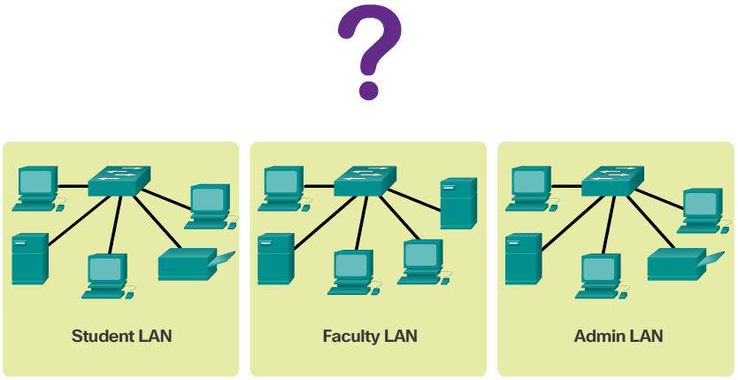 X
X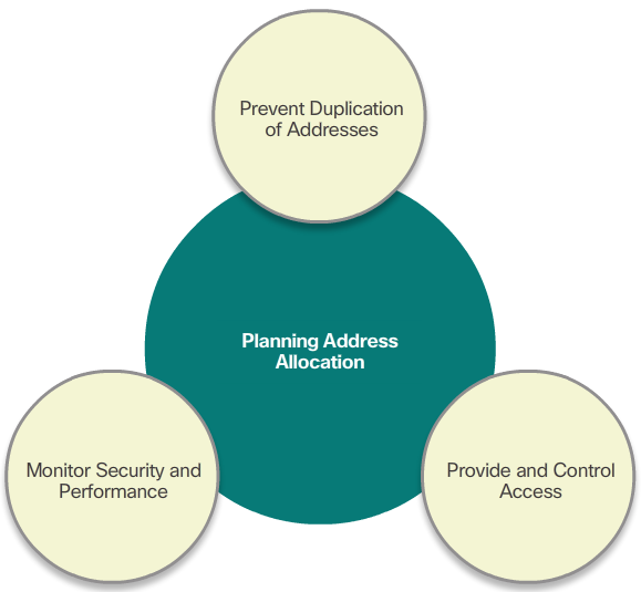
-

Subnetting Using the Subnet ID
- The 16 bit subnet ID section of the IPv6 global unicast address can be used by an organization to create internal subnets.
- The subnet ID provides more than enough subnets and host support than will ever be needed in one subnet. For instance, the 16 bit section can:
- Create up to 65,536 /64 subnets. This does not include the possibility of borrowing any bits from the interface ID of the address.
- Support up to 18 quintillion host IPv6 addresses per subnet (i.e., 18,000,000,000,000,000,000).
- Note: Subnetting into the 64 bit Interface ID (or host portion) is also possible but it is rarely required.
- IPv6 subnetting is also easier to implement than IPv4, because there is no conversion to binary required. To determine the next available subnet, just count up in hexadecimal.
- For example, assume an organization has been assigned the 2001:0DB8:ACAD::/48 global routing prefix with a 16 bit subnet ID. This would allow the organization to create /64 subnets, as shown in the 📷 figure. Notice how the global routing prefix is the same for all subnets. Only the subnet ID hextet is incremented in hexadecimal for each subnet.
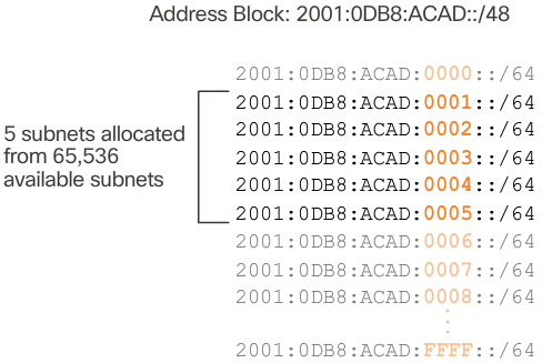
IPv6 Subnet Allocation
- With over 65,000 subnets to choose from, the task of the network administrator becomes one of designing a logical scheme to address the network.
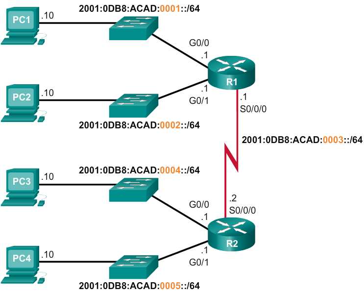
- As shown in Figure 1, the example topology will require subnets for each LAN as well as for the WAN link between R1 and R2. Unlike the example for IPv4, with IPv6 the WAN link subnet will not be subnetted further. Although this may “waste” addresses, that is not a concern when using IPv6.
- As shown in Figure 2, the allocation of five IPv6 subnets, with the subnet ID field 0001 through 0005 will be used for this example. Each /64 subnet will provide more addresses than will ever be needed.
- As shown in Figure 3, each LAN segment and the WAN link is assigned a /64 subnet.
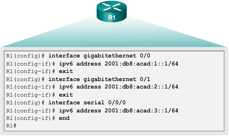
- Similar to configuring IPv4, Figure 4 shows that each of the router interfaces has been configured to be on a different IPv6 subnet.
X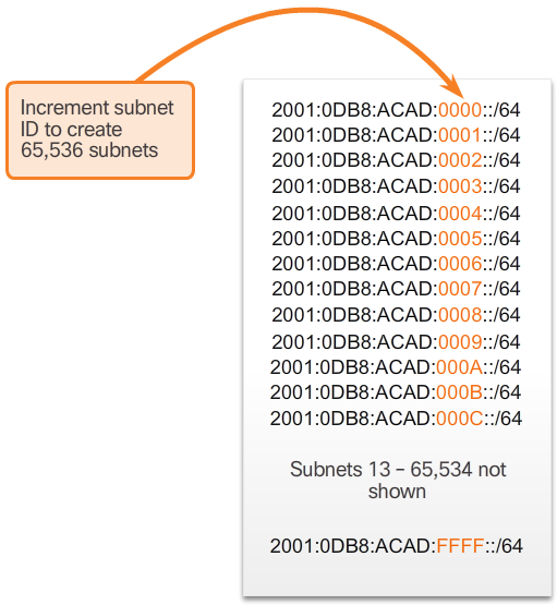
-
Summary
- In this chapter, you learned that:
- Subnetting is the process of segmenting a network, by dividing it into multiple smaller network spaces.
- Subnetting a subnet, or using VLSM, was designed to avoid wasting addresses.
- IPv6 address space is subnetted to support the hierarchical, logical design of the network.
- Size, location, use, and access requirements are all considerations in the address planning process.
- IP networks must be tested to verify connectivity and operational performance.