09
-

Chapter 9: Objectives
- Describe the purpose of the transport layer in managing the transportation of data in end-to-end communication.
- Describe characteristics of the TCP and UDP protocols, including port numbers and their uses.
- Explain how TCP session establishment and termination processes facilitate reliable communication.
- Explain how TCP protocol data units are transmitted and acknowledged to guarantee delivery.
- Explain the UDP client processes to establish communication with a server.
- Determine whether high-reliability TCP transmissions, or non-guaranteed UDP transmissions, are best suited for common applications.
Chapter 9
- Transport Layer Protocols
- TCP and UDP
- Summary
-
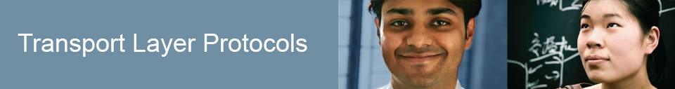
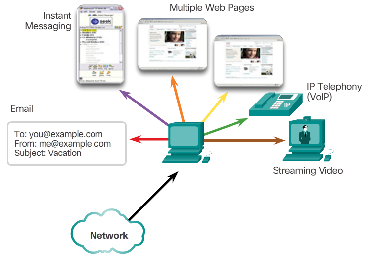
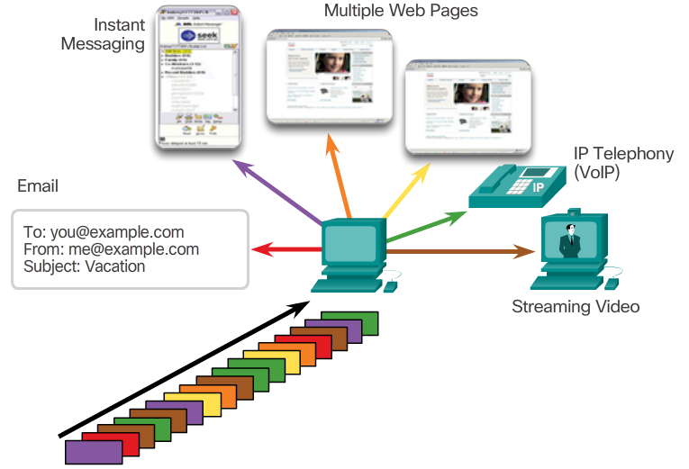
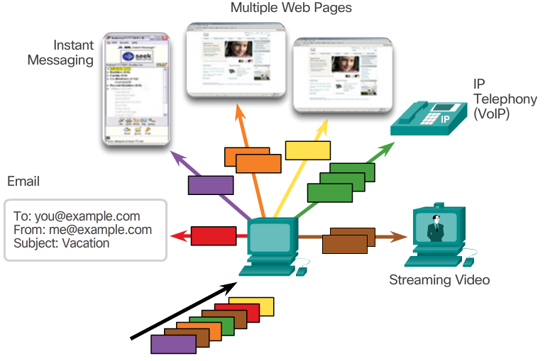
Conversation Multiplexing
- Sending some types of data (for example, a streaming video) across a network, as one complete communication stream, can consume all of the available bandwidth. This will then prevent other communications from occurring at the same time. It would also make error recovery and retransmission of damaged data difficult.
- The 📷 figure shows that segmenting the data into smaller chunks enables many different communications, from many different users, to be interleaved (multiplexed) on the same network.
- To identify each segment of data, the transport layer adds a header containing binary data organized into several fields. It is the values in these fields that enable various transport layer protocols to perform different functions in managing data communication.
Role of the Transport Layer
- The transport layer is responsible for establishing a temporary communication session between two applications and delivering data between them. An application generates data that is sent from an application on a source host to an application on a destination host. This is without regard to the destination host type, the type of media over which the data must travel, the path taken by the data, the congestion on a link, or the size of the network. As shown in the figure, the transport layer is the link between the application layer and the lower layers that are responsible for network transmission.
- 📷 View Diagram
Transport Layer Responsibilities
- Tracking Individual Conversations
- At the transport layer, each set of data flowing between a source application and a destination application is known as a conversation (Figure 1). A host may have multiple applications that are communicating across the network simultaneously. Each of these applications communicates with one or more applications on one or more remote hosts. It is the responsibility of the transport layer to maintain and track these multiple conversations.
- Segmenting Data and Reassembling Segments
- Data must be prepared to be sent across the media in manageable pieces. Most networks have a limitation on the amount of data that can be included in a single packet. Transport layer protocols have services that segment the application data into blocks that are an appropriate size (Figure 2). This service includes the encapsulation required on each piece of data. A header, used for reassembly, is added to each block of data. This header is used to track the data stream.
- At the destination, the transport layer must be able to reconstruct the pieces of data into a complete data stream that is useful to the application layer. The protocols at the transport layer describe how the transport layer header information is used to reassemble the data pieces into streams to be passed to the application layer.
- Identifying the Applications
- To pass data streams to the proper applications, the transport layer must identify the target application (Figure 3). To accomplish this, the transport layer assigns each application an identifier called a port number. Each software process that needs to access the network is assigned a port number unique to that host.
X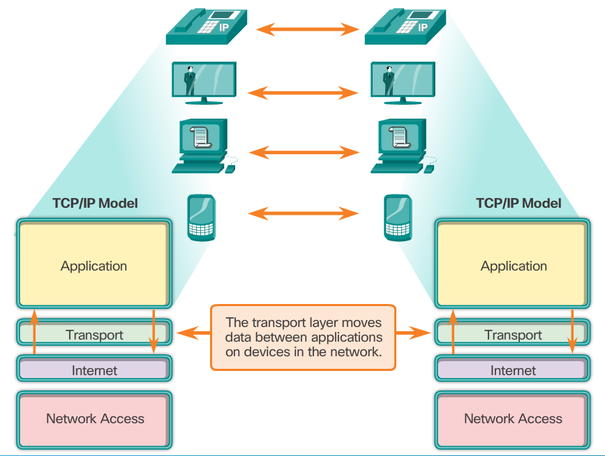 X
X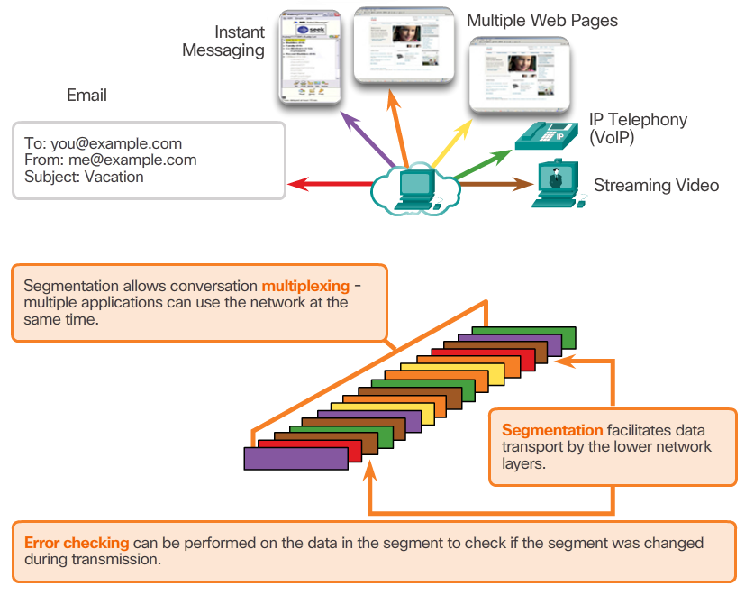
-
TCP Features
- To understand the differences between TCP and UDP, it is important to understand how each protocol implements specific reliability features and how they track conversations. In addition to supporting the basic functions of data segmentation and reassembly, TCP, also provides other services.
- Establishing a Session
- TCP is a connection-oriented protocol. A connection-oriented protocol is one that negotiates and establishes a permanent connection (or session) between source and destination devices prior to forwarding any traffic. Through session establishment, the devices negotiate the amount of traffic that can be forwarded at a given time, and the communication data between the two can be closely managed.
- Reliable Delivery
- In networking terms, reliability means ensuring that each segment that the source sends arrives at the destination. For many reasons, it is possible for a segment to become corrupted or lost completely, as it is transmitted over the network.
- Same-Order Delivery
- Because networks may provide multiple routes that can have different transmission rates, data can arrive in the wrong order. By numbering and sequencing the segments, TCP can ensure that these segments are reassembled into the proper order.
- Flow Control
- Network hosts have limited resources, such as memory and processing power. When TCP is aware that these resources are overtaxed, it can request that the sending application reduce the rate of data flow. This is done by TCP regulating the amount of data the source transmits. Flow control can prevent the need for retransmission of the data when the receiving host's resourses are overwhelmed.
- For more information on TCP, read the RFC.
Transport Layer Reliability
- The transport layer is also responsible for managing reliability requirements of a conversation. Different applications have different transport reliability requirements.
- IP is concerned only with the structure, addressing, and routing of packets. IP does not specify how the delivery or transportation of the packets takes place. Transport protocols specify how to transfer messages between hosts. TCP/IP provides two transport layer protocols, Transmission Control Protocol (TCP) and User Datagram Protocol (UDP). IP uses these transport protocols to enable hosts to communicate and transfer data.
- TCP is considered a reliable, full-featured transport layer protocol, which ensures that all of the data arrives at the destination. In contrast, UDP is a very simple transport layer protocol that does not provide for any reliability.
TCP
- TCP transport is analogous to sending packages that are tracked from source to destination. If a shipping order is broken up into several packages, a customer can check online to see the order of the delivery.
- With TCP, there are three basic operations of reliability:
- Numbering and tracking data segments transmitted to a specific host from a specific application
- Acknowledging received data
- Retransmitting any unacknowledged data after a certain period of time
UDP
- While the TCP reliability functions provide more robust communication between applications, they also incur additional overhead and possible delays in transmission. There is a trade-off between the value of reliability and the burden it places on network resources. Adding overhead to ensure reliability for some applications could reduce the usefulness of the application and can even be detrimental. In such cases, UDP is a better transport protocol.
- UDP provides the basic functions for delivering data segments between the appropriate applications, with very little overhead and data checking. UDP is known as a best-effort delivery protocol. In the context of networking, best-effort delivery is referred to as unreliable because there is no acknowledgment that the data is received at the destination. With UDP, there are no transport layer processes that inform the sender of a successful delivery.
- UDP is similar to placing a regular, non-registered, letter in the mail. The sender of the letter is not aware of the availability of the receiver to receive the letter. Nor is the post office responsible for tracking the letter or informing the sender if the letter does not arrive at the final destination.
-
Multiple Separate Conversations
- The transport layer must be able to separate and manage multiple communications with different transport requirement needs. Users expect to be able to simultaneously receive and send email and instant messages, view websites, and conduct a VoIP phone call. Each of these applications is sending and receiving data over the network at the same time, despite different reliability requirements. Additionally, data from the phone call is not directed to the web browser, and text from an instant message does not appear in an email.
- TCP and UDP manage these multiple simultaneous conversations by using header fields that can uniquely identify these applications. These unique identifiers are the port numbers.
Port Numbers
- The source port number is associated with the originating application on the local host. The destination port number is associated with the destination application on the remote host.
- Source Port
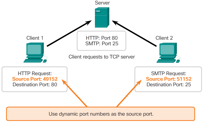
- The source port number is dynamically generated by the sending device to identify a conversation between two devices. This process allows multiple conversations to occur simultaneously. It is common for a device to send multiple HTTP service requests to a web server at the same time. Each separate HTTP conversation is tracked based on the source ports.
- Destination Port
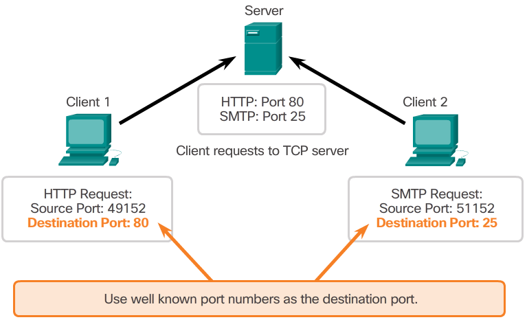
- The client places a destination port number in the segment to tell the destination server what service is being requested. For example, when a client specifies port 80 in the destination port, the server that receives the message knows that web services are being requested. A server can offer more than one service simultaneously such as web services on port 80 at the same time that it offers File Transfer Protocol (FTP) connection establishment on port 21.
TCP Header
- TCP is a stateful protocol. A stateful protocol is a protocol that keeps track of the state of the communication session. To track the state of a session, TCP records which information it has sent and which information has been acknowledged. The stateful session begins with the session establishment and ends when closed with the session termination.
- Each TCP segment has 20 bytes of overhead in the header encapsulating the application layer data:
- Source Port (16 bits) and Destination Port (16 bits) - Used to identify the application.
- Sequence number (32 bits) - Used for data reassembly purposes.
- Acknowledgment number (32 bits) - Indicates the data that has been received.
- Header length (4 bits) - Known as ʺdata offsetʺ. Indicates the length of the TCP segment header.
- Reserved (6 bits) - This field is reserved for the future.
- Control bits (6 bits) - Includes bit codes, or flags, which indicate the purpose and function of the TCP segment.
- Window size (16 bits) - Indicates the number of bytes that can be accepted at one time.
- Checksum (16 bits) - Used for error checking of the segment header and data.
- Urgent (16 bits) - Indicates if data is urgent.
UDP Features
- User Datagram Protocol (UDP) is considered a best-effort transport protocol. UDP is a lightweight transport protocol that offers the same data segmentation and reassembly as TCP, but without TCP reliability and flow control. UDP is such a simple protocol that it is usually described in terms of what it does not do compared to TCP.
- The features of UDP are described in the 📷 figure.
- For more information on UDP, read the RFC.
UDP Header
- UDP is a stateless protocol, meaning neither the client, nor the server, is obligated to keep track of the state of the communication session. If reliability is required when using UDP as the transport protocol, it must be handled by the application.
- One of the most important requirements for delivering live video and voice over the network is that the data continues to flow quickly. Live video and voice applications can tolerate some data loss with minimal or no noticeable effect, and are perfectly suited to UDP.
- The pieces of communication in UDP are called datagrams. These datagrams are sent as best-effort by the transport layer protocol. UDP has a low overhead of 8 bytes.
X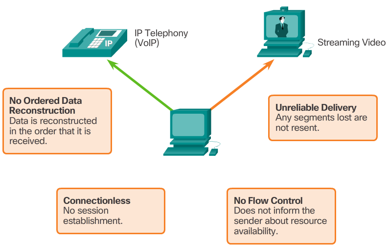
-
Port Number Range Port Group 0 to 1023 Well-known Ports 1024 to 49151 Registered Ports 49152 to 65535 Private and/or Dynamic Ports Port Number Protocol Application Acronym 20 TCP File Transfer Protocol (data) FTP 21 TCP File Transfer Protocol (control) FTP 22 TCP Secure Shell SSH 23 TCP Telnet - 25 TCP Simple Mail Transfer Protocol SMTP 53 UDP, TCP Domain Name Service DNS 67 UDP Dynamic Host Configuration Protocol (server) DHCP 68 UDP Dynamic Host Configuration Protocol (client) DHCP 69 UDP Trivial File Transfer Protocol TFTP 80 TCP Hypertext Transfer Protocol HTTP 110 TCP Post Office Protocol version 3 POP3 143 TCP Internet Message Access Protocol IMAP 161 UDP Simple Network Management Protocol SNMP 443 TCP Hypertext Transfer Protocol Secure HTTPS The netstat Command
- Unexplained TCP connections can pose a major security threat. They can indicate that something or someone is connected to the local host. Sometimes it is necessary to know which active TCP connections are open and running on a networked host. Netstat is an important network utility that can be used to verify those connections. As shown in the 📷 figure, enter the command netstat to list the protocols in use, the local address and port numbers, the foreign address and port numbers, and the connection state.
- By default, the netstat command will attempt to resolve IP addresses to domain names and port numbers to well-known applications. The -n option can be used to display IP addresses and port numbers in their numerical form.
Socket Pairs
- The source and destination ports are placed within the segment. The segments are then encapsulated within an IP packet. The IP packet contains the IP address of the source and destination. The combination of the source IP address and source port number, or the destination IP address and destination port number is known as a socket. The socket is used to identify the server and service being requested by the client. A client socket might look like this, with 1099 representing the source port number: 192.168.1.5:1099
- The socket on a web server might be: 192.168.1.7:80
- Together, these two sockets combine to form a socket pair: 192.168.1.5:1099, 192.168.1.7:80
- Sockets enable multiple processes, running on a client, to distinguish themselves from each other, and multiple connections to a server process to be distinguished from each other.
- The source port number acts as a return address for the requesting application. The transport layer keeps track of this port and the application that initiated the request so that when a response is returned, it can be forwarded to the correct application.
- 📷 View Diagram
Port Number Groups
- The Internet Assigned Numbers Authority (IANA) is the standards body responsible for assigning various addressing standards, including port numbers. There are different types of port numbers, as shown in Figure 1:
- Well-known Ports (Numbers 0 to 1023) - These numbers are reserved for services and applications. They are commonly used for applications such as web browsers, email clients, and remote access clients. By defining these well-known ports for server applications, client applications can be programmed to request a connection to that specific port and its associated service.
- Registered Ports (Numbers 1024 to 49151) - These port numbers are assigned by IANA to a requesting entity to use with specific processes or applications. These processes are primarily individual applications that a user has chosen to install, rather than common applications that would receive a well-known port number. For example, Cisco has registered port 1985 for its Hot Standby Routing Protocol (HSRP) process.
- Dynamic or Private Ports (Numbers 49152 to 65535) - Also known as ephemeral ports, these are usually assigned dynamically by the client’s OS when a connection to a service is initiated. The dynamic port is then used to identify the client application during communication.
- Note: Some client operating systems may use registered port numbers instead of dynamic port numbers for assigning source ports. Figure 2 displays some common well-known port numbers and their associated applications. Some applications may use both TCP and UDP. For example, DNS uses UDP when clients send requests to a DNS server. However, communication between two DNS servers always uses TCP. Click here to view the full list of port numbers and associated applications at IANA’s website.
X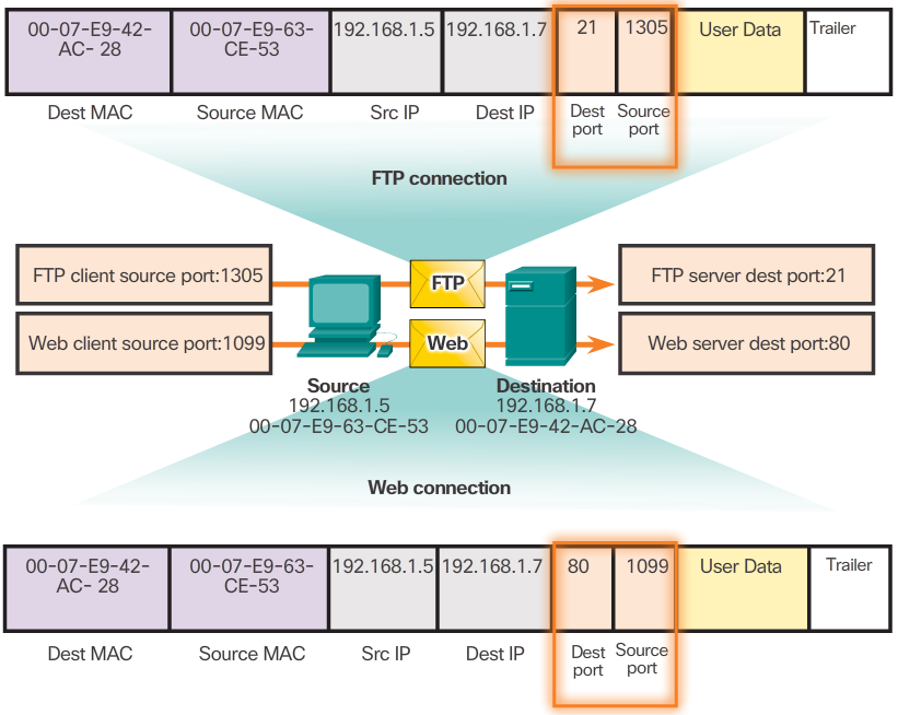 X
X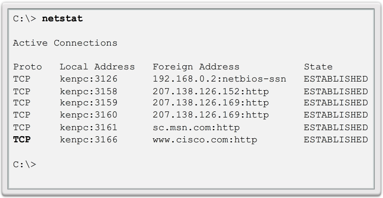
-

TCP Connection Establishment
- In some cultures, when two persons meet, they often greet each other by shaking hands. The act of shaking hands is understood by both parties as a signal for a friendly greeting. Connections on the network are similar. In TCP connections, the host client establishes the connection with the server.
- A TCP connection is established in three steps:
- Step 1 - The initiating client requests a client-to-server communication session with the server.
- Step 2 - The server acknowledges the client-to-server communication session and requests a server-to-client communication session.
- Step 3 - The initiating client acknowledges the server-to-client communication session.
TCP Session Termination
- To close a connection, the Finish (FIN) control flag must be set in the segment header. To end each one-way TCP session, a two-way handshake, consisting of a FIN segment and an Acknowledgment (ACK) segment, is used. Therefore, to terminate a single conversation supported by TCP, four exchanges are needed to end both sessions.
- Note: In this explanation, the terms client and server are used as a reference for simplicity, but the termination process can be initiated by any two hosts that have an open session:
- Step 1 - When the client has no more data to send in the stream, it sends a segment with the FIN flag set.
- Step 2 - The server sends an ACK to acknowledge the receipt of the FIN to terminate the session from client to server.
- Step 3 - The server sends a FIN to the client to terminate the server-to-client session.
- Step 4 - The client responds with an ACK to acknowledge the FIN from the server.
- When all segments have been acknowledged, the session is closed.
TCP Server Processes
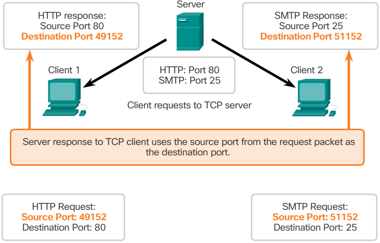
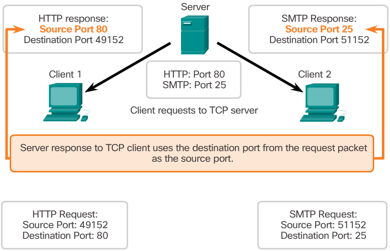
- Each application process running on the server is configured to use a port number, either by default or manually, by a system administrator. An individual server cannot have two services assigned to the same port number within the same transport layer services.
- For example, a host running a web server application and a file transfer application cannot have both configured to use the same port (for example, TCP port 80). An active server application assigned to a specific port is considered to be open, which means that the transport layer accepts and processes segments addressed to that port. Any incoming client request addressed to the correct socket is accepted, and the data is passed to the server application. There can be many ports open simultaneously on a server, one for each active server application.
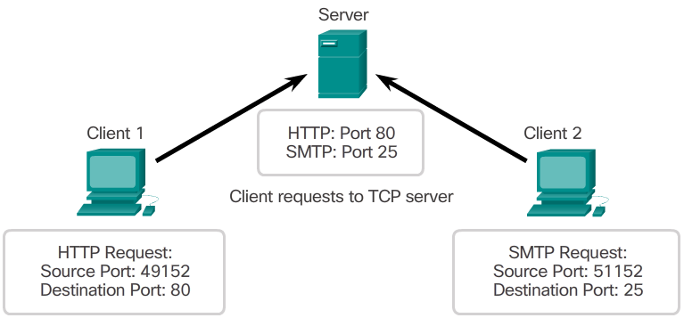
- Refer to Figures 1 through 5 to see the typical allocation of source and destination ports in TCP client/server operations.
-
Window Size and Acknowledgments cont...
- The initial window size is agreed upon when the TCP session is established during the three-way handshake. The source device must limit the number of bytes sent to the destination device based on the destination’s window size. Only after the source device receives an acknowledgment that the bytes have been received, can it continue sending more data for the session. Typically, the destination will not wait for all the bytes for its window size to be received before replying with an acknowledgment. As the bytes are received and processed, the destination will send acknowledgments to inform the source that it can continue to send additional bytes.
- Typically, PC B will not wait until all 10,000 bytes have been received before sending an acknowledgment. This means PC A can adjust its send window as it receives acknowledgments from PC B. As shown in the figure, when PC A receives an acknowledgment with the acknowledgment number 2,921, PC A’s send window will increment another 10,000 bytes (the size of PC B’s current window size) to 12,920. PC A can now continue to send up to another 10,000 bytes to PC B as long as it does not send past its new send window at 12,920.
- The process of the destination sending acknowledgments as it processes bytes received and the continual adjustment of the source’s send window is known as sliding windows.
- If the availability of the destination’s buffer space decreases, it may reduce its window size to inform the source to reduce the number of bytes it should send without receiving an acknowledgment.
TCP Reliability - Ordered Delivery
- TCP segments may arrive at their destination out of order. For the original message to be understood by the recipient, the data in these segments is reassembled into the original order. Sequence numbers are assigned in the header of each packet to achieve this goal. The sequence number represents the first data byte of the TCP segment.
- During session setup, an initial sequence number (ISN) is set. This ISN represents the starting value of the bytes for this session that is transmitted to the receiving application. As data is transmitted during the session, the sequence number is incremented by the number of bytes that have been transmitted. This data byte tracking enables each segment to be uniquely identified and acknowledged. Missing segments can then be identified.
- Note: The ISN does not begin at one but is effectively a random number. This is to prevent certain types of malicious attacks. For simplicity, we will use an ISN of 1 for the examples in this chapter.
- Segment sequence numbers indicate how to reassemble and reorder received segments, as shown in the 📷 figure.
- The receiving TCP process places the data from a segment into a receiving buffer. Segments are placed in the proper sequence order and passed to the application layer when reassembled. Any segments that arrive with sequence numbers that are out of order are held for later processing. Then, when the segments with the missing bytes arrive, these segments are processed in order.
Window Size and Acknowledgments
- TCP also provides mechanisms for flow control, the amount of data that the destination can receive and process reliably. Flow control helps maintain the reliability of TCP transmission by adjusting the rate of data flow between source and destination for a given session. To accomplish this, the TCP header includes a 16-bit field called the window size.
- The 📷 figure shows an example of window size and acknowledgments. The window size is the number of bytes that the destination device of a TCP session can accept and process at one time. In this example, PC B’s initial window size for the TCP session is 10,000 bytes. Starting with the first byte, byte number 1, the last byte PC A can send without receiving an acknowledgment is byte 10,000. This is known as PC A’s send window. The window size is included in every TCP segment so the destination can modify the window size at any time depending on buffer availability.
- Note: In the 📷 figure, the source is transmitting 1,460 bytes of data within each TCP segment. This is known as the MSS (Maximum Segment Size). Refer to the Chapter Appendix for more information on MSS.
X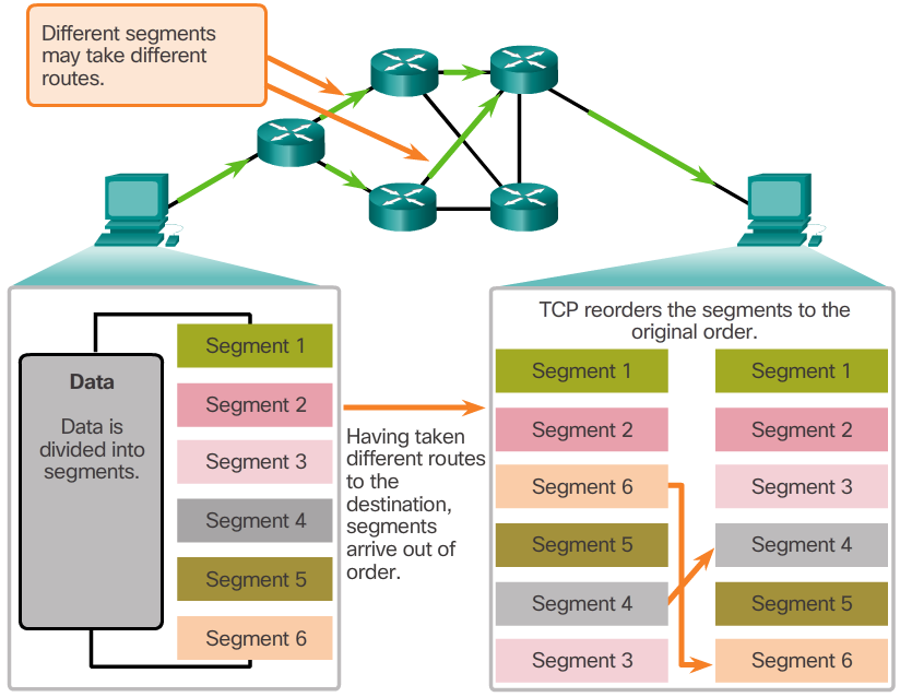 X
X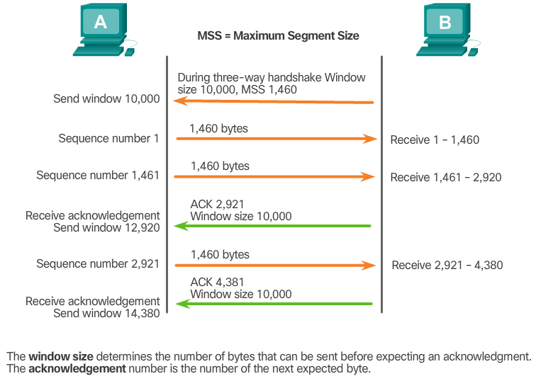
-
UDP Datagram Reassembly
- Like segments with TCP, when UDP datagrams are sent to a destination, they often take different paths and arrive in the wrong order. UDP does not track sequence numbers the way TCP does. UDP has no way to reorder the datagrams into their transmission order, as shown in the 📷 figure.
- Therefore, UDP simply reassembles the data in the order that it was received and forwards it to the application. If the data sequence is important to the application, the application must identify the proper sequence and determine how the data should be processed.
UDP Server Processes and Requests
- Like TCP-based applications, UDP-based server applications are assigned well-known or registered port numbers, as shown in the 📷 figure. When these applications or processes are running on a server, they accept the data matched with the assigned port number. When UDP receives a datagram destined for one of these ports, it forwards the application data to the appropriate application based on its port number.
- Note: The Remote Authentication Dial-in User Service (RADIUS) server shown in the 📷 figure provides authentication, authorization, and accounting services to manage user access. The operation of RADIUS is beyond scope for this course.
Congestion Avoidance
- When congestion occurs on a network, it results in packets being discarded by the overloaded router. When packets containing TCP segments don’t reach their destination, they are left unacknowledged. By determining the rate at which TCP segments are sent but not acknowledged, the source can assume a certain level of network congestion.
- Whenever there is congestion, retransmission of lost TCP segments from the source will occur. If the retransmission is not properly controlled, the additional retransmission of the TCP segments can make the congestion even worse. Not only are new packets with TCP segments introduced into the network, but the feedback effect of the retransmitted TCP segments that were lost will also add to the congestion. To avoid and control congestion, TCP employs several congestion handling mechanisms, timers, and algorithms.
- If the source determines that the TCP segments are either not being acknowledged or not acknowledged in a timely manner, then it can reduce the number of bytes it sends before receiving an acknowledgment. Notice that it is the source that is reducing the number of unacknowledged bytes it sends and not the window size determined by the destination.
- Note: Explanation of actual congestion handling mechanisms, timers, and algorithms are beyond the scope of this course.
UDP Low Overhead versus Reliability
- UDP is a simple protocol that provides the basic transport layer functions. It has much lower overhead than TCP because it is not connection-oriented and does not offer the sophisticated retransmission, sequencing, and flow control mechanisms that provide reliability.
- This does not mean that applications that use UDP are always unreliable, nor does it mean that UDP is an inferior protocol. It simply means that these functions are not provided by the transport layer protocol and must be implemented elsewhere if required.
- The low overhead of UDP makes it very desirable for protocols that make simple request and reply transactions. For example, using TCP for DHCP would introduce unnecessary network traffic. If there is a problem with a request or a reply, the device simply sends the request again if no response is received.
X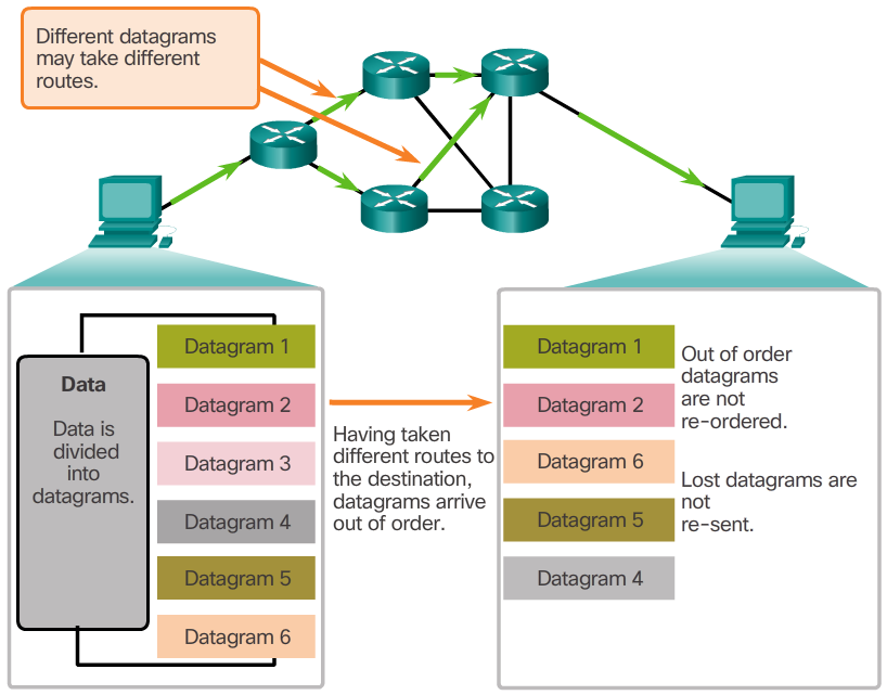 X
X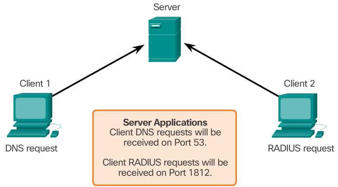
- Client requests to servers have well known port numbers as the destination port.
-
Applications that use UDP
- There are three types of applications that are best suited for UDP:
- Live video and multimedia applications - Can tolerate some data loss, but require little or no delay. Examples include VoIP and live streaming video.
- Simple request and reply applications - Applications with simple transactions where a host sends a request and may or may not receive a reply. Examples include DNS and DHCP.
- Applications that handle reliability themselves - Unidirectional communications where flow control, error detection, acknowledgments, and error recovery is not required or can be handled by the application. Examples include SNMP and TFTP.
- Although DNS and SNMP use UDP by default, both can also use TCP. DNS will use TCP if the DNS request or DNS response is more than 512 bytes, such as when a DNS response includes a large number of name resolutions. Similarly, under some situations the network administrator may want to configure SNMP to use TCP.
- 📷 View Diagram
UDP Client Processes
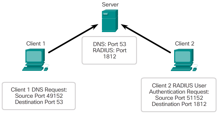
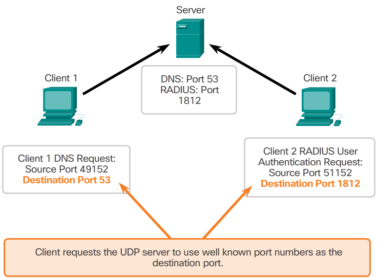
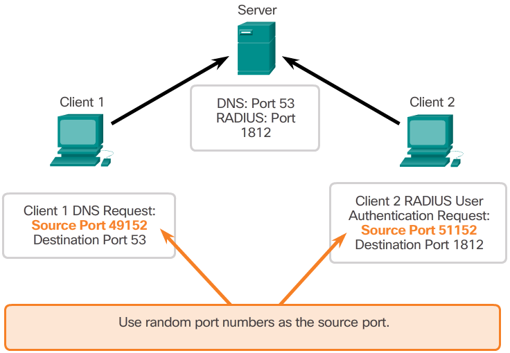
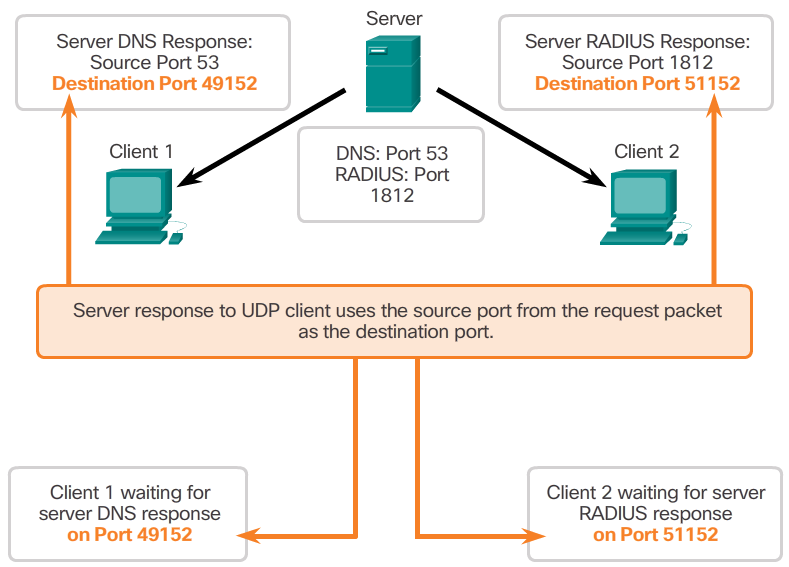
- As with TCP, client-server communication is initiated by a client application that requests data from a server process. The UDP client process dynamically selects a port number from the range of port numbers and uses this as the source port for the conversation. The destination port is usually the well-known or registered port number assigned to the server process.
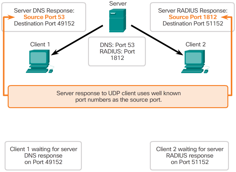
- After a client has selected the source and destination ports, the same pair of ports is used in the header of all datagrams used in the transaction. For the data returning to the client from the server, the source and destination port numbers in the datagram header are reversed.
- Click through Figures 1 through 5 to see details of the UDP client processes.
Applications that use TCP
- TCP is a great example of how the different layers of the TCP/IP protocol suite have specific roles. TCP handles all tasks associated with dividing the data stream into segments, providing reliability, controlling data flow, and the reordering of segments. TCP frees the application from having to manage any of these tasks. Applications, like those shown in the 📷 figure, can simply send the data stream to the transport layer and use the services of TCP.
X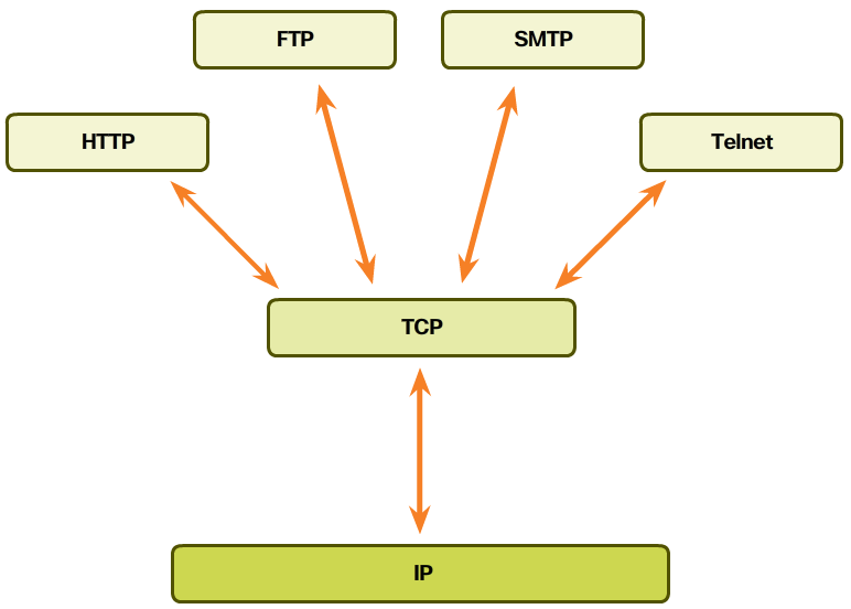 X
X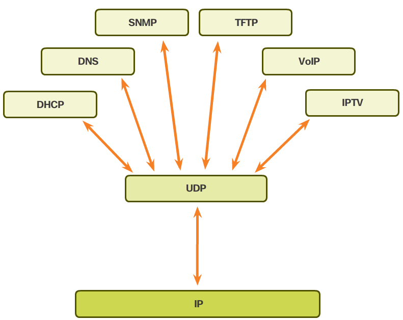
-
Summary
- In this chapter, you learned:
- The role of the transport layer is to provide three main services: multiplexing, segmentation and reassembly, and error checking. It does this by:
- Dividing data received from an application into segments.
- Adding a header to identify and manage each segment.
- Using the header information to reassemble the segments back into application data.
- Passing the assembled data to the correct application.
- How TCP and UDP operate and which popular applications use each protocol.
- Transport Layer functions are necessary to address issues in QoS and security in networks.
- Ports provide a “tunnel” for data to get from the transport layer to the appropriate application at the destination.