-
Software Requirement: case study
Objectives
- Use case modelling
- Activity modelling
- Class modelling
- Database design
-
Stakeholders
- Any person or organisation who is affected by the system in some way and so who has a legitimate interest. Any one who is affected by the system or who has influence on system development or use the system is a stakeholder.
- For example:
- Customers (e.g. End users and system owner(s), system managers)
- Developers (requirement/system analyst, 3D designers, programmers, project manager etc.)
- External stakeholders
What are the main factors which cause software failure?
- Customer as stakeholder:
- Didn’t meet the customer’s needs or misunderstood/ not fully captured their requirements.
- Change requirements too often
- Customers are lack of commitment to the project
- Customers don’t understand the terminology,
- Lack of communication with developers
- Customers have unrealistic/high expectation to the project.
- The system is no longer benefit to the business or customers.
Scenario: Online Furniture Purchase
The following scenario will be used to discuss the Use Case Modelling Approach to Requirements Capture.
Requirements:
- 1. Mr John Smith would like to purchase 3-seater sofas over Internet using the manufacturer’s web site which is called furniture4u.co.uk. This is family run business and provide great costumer services.
- 2. Computers classified into servers, desktops and portables e.g. tablet and mobile phone device.
- 3. Customer can select colour, fibre and style and delivery date, the system will able to the calculate total price.
- 4. To place order, the customer must join the membership and fill out the personal information, shipment and payment information.
- 5. New member will be given his/her user name and password
- 6. The system sends a confirmation e-mail message to the customer with details of the order.
- 7. Customer can check the order status, online and shipping details at any time when they login the system. The system should also allow the customer to cancel order or amend order. The system should able to process refund.
- 8. Additionally, the system should able to
- verify the customer’s credentials and provide payment methods such as paypal, credit card or debit card payments.
- request the ordered from the factory,
- print an invoice and also send an invoice by email, to the customer, and
- request the factory to ship the sofas to the customer.
- 9. This company uses shipping.com to shipping their furniture to their company. (Outsourcing)
-
How to identify actors?
- Actor represents a role that interacts with the system. Such as human e.g. end users, system managers; time e.g. can trigger event: automatic send an ordering confirmation email to customer. ;hardware device e.g. printer, data projector etc.
Tip:
- 1. look all the nouns in your scenario e.g. customer, salesman etc.
- 2. Actor names should clearly indicate the actor’s job role. E.g. if John is a student as a actor. You should use student as your actor’s name rather than John because John is not able to represent all the students. That is why we need to name the actor as actor’s role.
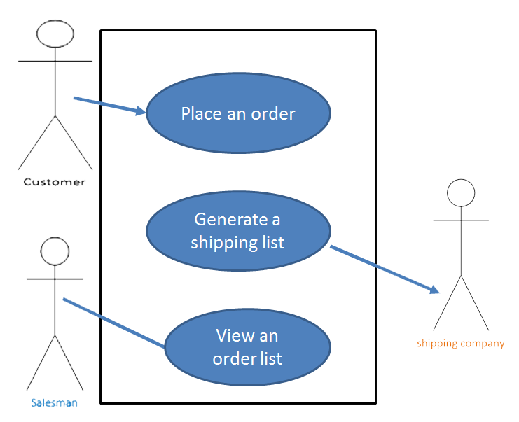
Identify – actors
- Consider the following requirements:
- The customer may choose to order a sofa online or
- may through online contact us function to make an request that the salesman contact him/her to explain order details, negotiate the price, etc. before the order is actually placed.
- The factory Amin obtains the invoice from the
- salesman and pass shipping detail to shipping.com to ships the sofa(s) to the customer.
- So the potential actors are : Customer, Salesman, factory and shipping company
What is use-case modelling?
- A use-case model describes a system’s functional requirements in terms of use cases.
- Links and meets to stakeholders needs to software requirements
- Defines clear boundaries of a system
- Captures and communicates the desired behaviour of the system
- Identifies who or what interacts with the system (actors)
- Validates/verifies requirements
- It is very powerful planning instrument, it is generally used in all phases of the development cycle by all software development team members.
- A use-case model consists of both diagrams and text.
- The diagrams give a visual overview of the system.
- The text gives descriptions of the actors and the use case
- Use cases only deal with Functional requirements
How to create a use-case model
- 1. Identify actors and use cases in scenario
- Define each actor by writing a brief description that includes the actor’s responsibility and what the actor needs from the system for.
- 2. Write the use cases
- Outline all use cases
- Prioritize the use-case flows
- Detail the flows in order of priority
- When actors and use cases have been identified, each use case is described in details which show how the system interacts with the actors and what the system does in each individual case/
-
Define use case
- A use case describes a set of possible executions of the system.
- A use case defines a sequence of actions performed by a system that produces an observable result of value to an actor.
How to identify use cases
- Use case represents something of value that the system does for its actors.
- A use care describes:
- The system, its environment and the relationship between them.
- How things outside the system interact with the system
- The desired behaviour for the system
Tip:
- Use case begins with a verb
- Indicate the value or goal of the actor
- Look all the verbs in your scenario e.g. order, request, print etc.
Identify use cases
- Consider the following requirements:
- The customer may choose to order sofa(s) online or
- may through online contact us function to make an request that the salesman contact him/her to explain order details, negotiate the price, etc. before the order is actually placed.
- The factory Admin obtains the invoice from the salesman and ships the sofa(s) to the customer.
- Order sofa(s)
- Request Print Invoice
- Request Salesman Contact
-
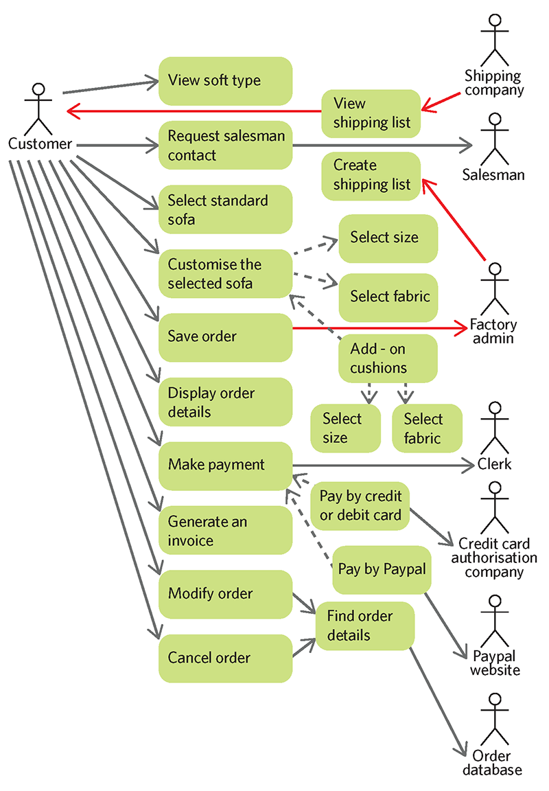
Communicates-Associations in use-case diagram
- A channel of communication between an actor and a use case.
- Relationships between actors and used cases are called communicates-associations.
- A line is used to represent a relationship between actors and use cases.
- An arrowhead is used to indicate who initiated the interaction
- No arrowhead indicates either end can initiate each interaction.
Example of Communicates-Associations
- Actor: customer always initiates communication with the system.
- The system may respond to messages from actor: customer but can never send an unsolicited message to customer., the system always initiated communication with Actor: shipping company.
- Actor: shipping company may respond to message to the system, but can never send an unsolicited message to the system. For the actor: salesman or the system may initiate the dialog.
-
Use case Form
Use Case Name Place order Description This use case allows a customer to purchase furniture online. This includes proving shipping detail and invoice address and payment details. Actors Primary: customer; salesman Priority High Risk High Assumptions One or more sofas have been added to the system. One or more sofa types Pre-conditions Customer points Internet browser to the furniture’s order entry website. The page displays the details of choices colours, fibres and styles together with total costs. Extension Points Payment Extends None Trigger A customer wishes to place order via salesman Main Flow of Events 1. Salesman enters the required sofa type, colour and fibre. [A1] [A2]
2. System checks if a sofa of that style is available. [A3]
3. System notifies that a sofa is available and calculate total price.
4. Customer accepts sofa offered. [A5]
5. Extension Point (payment). [A6]
6. System records order.
7. System displays order number and automatic send out confirmation order to customer’s email address.Alternative flow Of Events A1. The colour/fibre is not available. Display message and return to step 1.
A2. Sofa style invalid. Display message. Return to step 1.
A3. Sofa is out of product line for the required item. System changes sofa style for search. Return to step 2. [A4]
A4. No other Sofa style customer like it. Display message. Return to step 1.
A5. Sofa offer is declined. End of use case.
A6. Payment rejected. Display message. Return to step 5.
At any time use case can be cancelled.Post-condition New sofa style added. Colour/fibre available is reduced by the discount/on sale period.
Payment details are recorded. If the use case was successful, the purchase order is recorded in the system’s database. Otherwise, the system’s state is unchanged.Non-Functional Requirements Successful use case must take no longer than 2 minutes to complete. Search for available sofas must take no longer than 30 seconds. This use case must be available 24/7. This use case up time must be 99.9% during each 24 hour period.
Can’t accept order without check the stock system.Issues Make use the online payment is secured. -
What is an activity diagram?
- Activity diagrams/ flow charts are useful tool which it can be use to describe a use case too.
- Activity diagrams use to describe complex flows of events.
- Each event is a state of doing something. For this reason, the execution events for an activity are called action states.
- The flow of control from on action state to next is called a flow.
- If a use-case document has been completed, then activities and action states can be discovered from he description of the main and alternative flows.
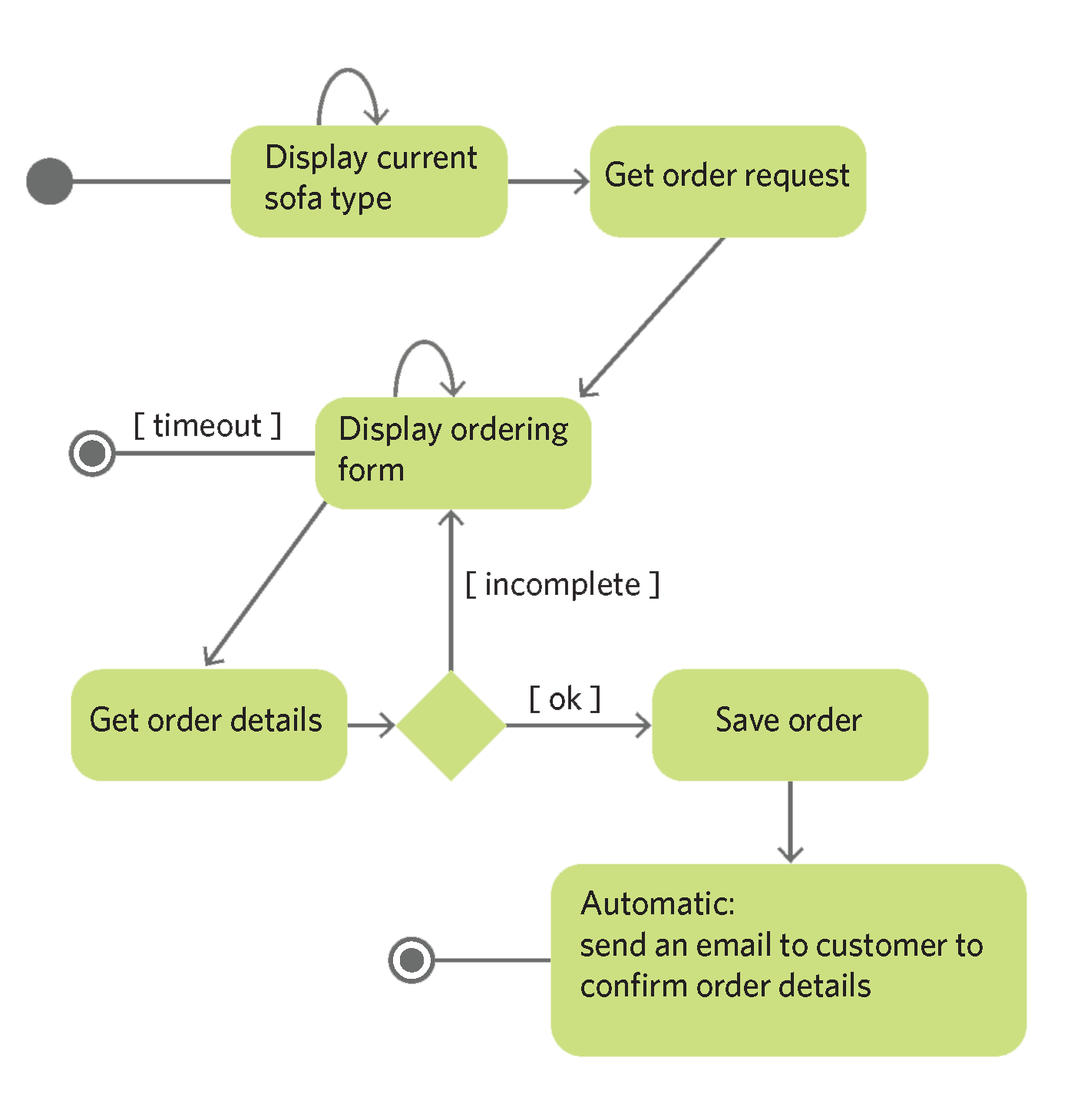
Activity diagram: notations
- An activity diagram shows flows between actions.
- The diagram has an initial action state and one or more final action states.
- A solid filled circle represents the initial state. The final state is shown using a two circles symbol. In side the circle is fully filled. E.g.

- Diamond box shows that branch condition. The exit from a branch condition is controlled by an event (such as yes, no) or by a guard condition e.g. excellent, good/poor)

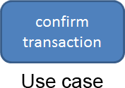
- Rectangle box shows the use cases. The use cases are beginning with verb e.g. display transaction detail, confirm transaction, and refuse transaction etc.
-
Activity diagram – actions
Actions : Process Order sofa(s)
- 1. Get Purchase Store Order:
- The Customer searches and then chooses the Purchase function to submit his/her order to the funiture4u.com website.
- 2. Store Order:
- The system assigns a unique order number to the customer and links to the customer account number to the purchase order.
- The order system will store the order’s details in the database.
- 3. Email the customer his/her ordering details
- The system automatic send e-mails to the Customer the Ordering Details which include the unique order number and the customer ID, total cost etc. as the confirmation of the order’s acceptance.
- P.S. If the customer didn’t find what he/she looking for or the item is not available, the system should give the customer another choice or to close the search.
-
Class attributes
- The structure of a class is defined by its attributes. Without attributes, we can’t store the data in the class. Finding meaningful and useful attributes are important. In practice, the main attributes are usually allocated to a class immediately after the class has been added to the model.
Tips for finding attributes
- Most attributes can be found from user requirements and from the domain knowledge.
- Step1 : work on defining identifying attributes for each class.
- Step 2: one ore more attributes in a class that have unique values across all instances of the class. E.g. orderID. It is called primary key or class key. Ideally, a primary key should consist of one attribute.
What is class diagram?
- Following the approach taken in finding actors and use cases, activity diagram, now we can construct a class diagram from the analysis of functional requirements.
- Entity classes define the functional requirements in software system.
- In class diagram, it includes class name, attributes and relationship between classes and operations/methods.
Tips for finding classes
- Finding classes is an interactive tasks.
- Step 1: list the initial list of possible candidate classes (check the actors, sometimes actors can be your classes)
- Step 2: Is the concept a container for data?
- Step 3: does it have separate attributes that will take on different values?
- Step 4: would it have many instance objects?
- Step 5: Is it in the scope of the application domain?
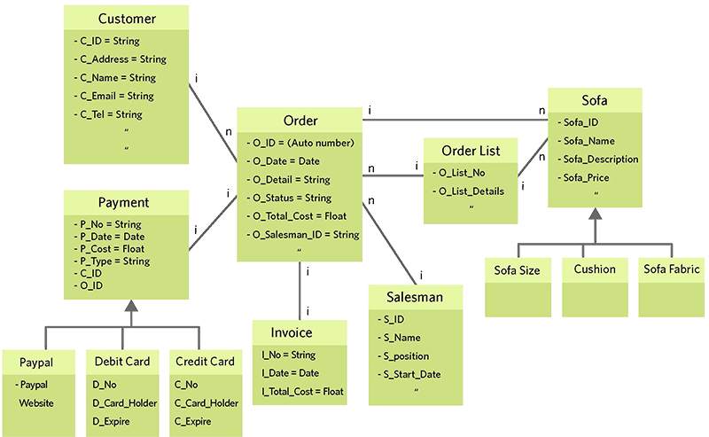
Class Diagram
- Associations between classes establish pathways for easy object collaboration.
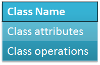
- Graphically, a class is represented as a rectangle with three compartments. From the top to the bottom compartments which are class name, class attributes and class operations/methods.
-
Class diagram-identify attributes
- Customer class’s attributes:
- cId: String
- cName: String
- cAddress: String
- cPhoneNumber: String
- cEmail:String
- Etc…
- order class’s attributes:
- orderID: String
- totalCost: float
- orderDate: Date
- shippingStatus: String
- orderPaid: Boolean
- Etc…
- furniture class’s attributes:
- furnitureID: String
- furnitureName: String
- furnitureDescription:String
- cost: float
- colour: String
- Fibre: String
- Style: String
- Etc…
- Orderlist class’s attributes:
- orderListID: String
- orderListName: String
- cost: float
- itemName: String
- itenId: String
- itemDescription: String
- cId: String
- Etc…
-
Associations-relationship between classes
- Associations between classes establish pathways for easy object collaboration.
- Graphically, a class is represented as a rectangle with three compartments. From the top to the bottom compartments which are class name, class attributes and class operations/methods.
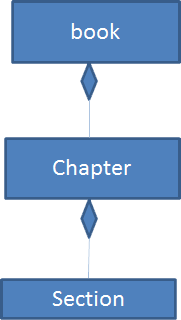
Class modelling-aggregations
- An aggregation is a whole-part relationship between a class representing an assembly of components (super/Parent class) and the classes representing he components (sub/child class).
- A super class contains a sub class.
- For example:
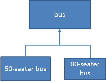
Inheritance
- A child class inherits from one parent class.
- Many child classes inherits from one parent class.
-
Class Diagram
Order Sofa
-
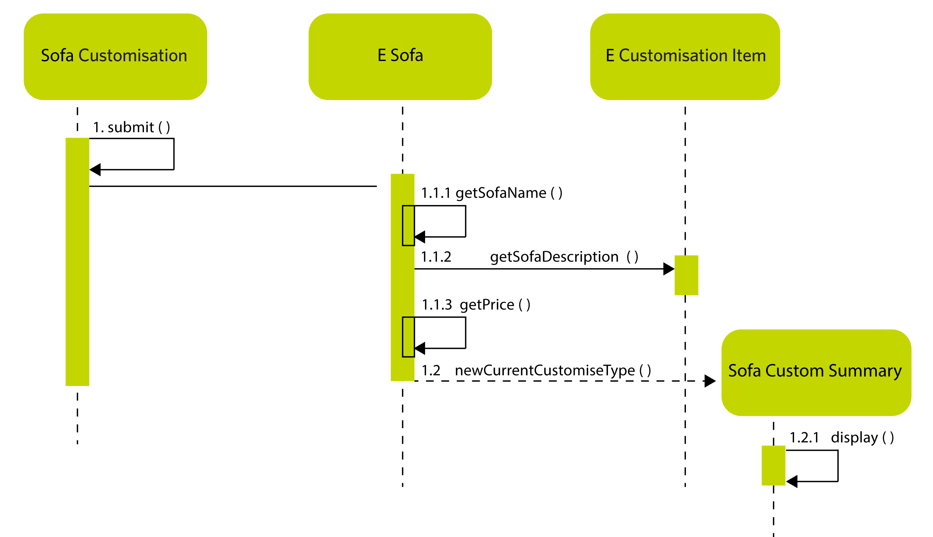
Sequence Diagram
- Only shows the classes extended with operations.
- Sequence diagram = for action "Display Current Customisation Sofa" (online shopping)
-
Computer architecture
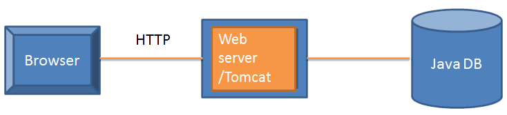
- “An architectural model for distributed systems where the system functionality is offered as set of services provided by a server. There ae accessed by client computers that make use of the services. Variants of this approach, such as three-tier client-server architectures, use multiple servers.” (Sommerville, 2011, pp.736)
Components
- A set of standards for component implementation, documentation and deployment. These cover the specific interfaces that may be provided by a component, component naming, component interoperation, and component composition. Component models provide the basis for middleware to support executing components.
- Component is a deployable, independent unit of software that is completely defined and accessed through a set of interfaces.
-
Glossary
ACDEFGILMOPRSUV
A
abstract class
- A class that can be used only as a superclass of some other class; no objects of an abstract class may be created except as instances of a subclass.
- Data source: Larman c. 2002 "Applying UML and Patterns", 2nd, Pearson. Pp.615
Activity diagram
- Activity diagrams/ flow charts are useful tool which it can be use to describe a use case too.
- Data source: lecture notes
Actor
- Actor represents a role that interacts with the system.
- Data source: lecture notes
actor role
- A named end of an association to indicate its purpose
- Data source: Larman c. 2002 "Applying UML and Patterns", 2nd, Pearson. Pp.618
aggregation
- A property of an association representing a whole-part relationship and (usually) life-time containment.
- Data source: Larman c. 2002 "Applying UML and Patterns", 2nd, Pearson. Pp.615
association
- A description of a related set of links between objects of two classes.
- Data source: Larman c. 2002 "Applying UML and Patterns", 2nd, Pearson. Pp.615
attribute
- A named characteristic or property that is the same for all instances of a class. This information is usually stored in the class definition.
- Data source: Larman c. 2002 "Applying UML and Patterns", 2nd, Pearson. Pp.615
Return to TopC
class
- In the UML , "The descriptor of a set of objects that share the same attributes, operations, methods, relationships, and behaviour. May be used to represent software or conception elements.
- Data source: Larman c. 2002 "Applying UML and Patterns", 2nd, Pearson. Pp.615
class diagram
- A UML diagram types that shows the object classes in a system and their relationships. Entity classes define the functional requirements in software system.
- Data source: Sommerville I. 2016"Software Engineering" 10th Edition. Pearson Pp.759
Client-Server architecture
- An architectural model for distributed systems where the system functionality is offered as set of services provided by a server. There ae accessed by client computers that make use of the services. Variants of this approach, such as three-tier client-server architectures, use multiple servers.
- Data source: Sommerville I. 2016"Software Engineering" 10th Edition. Pearson Pp.760
collaboration
- Two or more objects that participate in a client/server relationship in order to provide a service.
- Data source: Larman c. 2002 "Applying UML and Patterns", 2nd, Pearson. Pp.615
communicates-associations
- Relationships between actors and used cases are called communicates-associations.
- Data source: Lecture notes
component
- A deployable, independent unit of software that is completely defined and accessed through a set of interfaces.
- Data source: Sommerville I. 2016"Software Engineering" 10th Edition. Pearson Pp.760
component model
- A set of standards for component implementation, documentation and deployment. These cover the specific interfaces that may be provided by a component, component naming, component interoperation, and component composition. Component models provide the basis for middleware to support executing components.
- Sommerville I. 2016"Software Engineering" 10th Edition. Pearson Pp.760
composition
- The definition of a class in which each instance is comprised of other objects.
- Data source: Larman c. 2002 "Applying UML and Patterns", 2nd, Pearson. Pp.616
concept
- category of ideas or things. It used to designate real-world things rather than software entities. A concept's intension is a description of its attributes, operations and semantics. A concept's extension is the set of instances or example objects that are members of the concept. Often defined as a synonym for domain class.
- Data source: Larman c. 2002 "Applying UML and Patterns", 2nd, Pearson. Pp.616
conceptual design
- The development of a high-level vision of a complex system and a description of its essential capabilities. Designed to be understood by people who are not system engineers.
- Data source: Sommerville I. 2016"Software Engineering" 10th Edition. Pearson Pp.761
concrete class
- A class that can have instances
- Data source: Larman c. 2002 "Applying UML and Patterns", 2nd, Pearson. Pp.616
constraint
- A restriction or condition on an element.
- Data source: Larman c. 2002 "Applying UML and Patterns", 2nd, Pearson. Pp.616
coupling
- A dependency between elements (such as classes, packages, subsystems), typically resulting from collaboration between the elements to provides a service.
- Data source: Larman c. 2002 "Applying UML and Patterns", 2nd, Pearson. Pp.616
Return to TopD
design
- A process that uses the products of analysis to produce a specification for implementation details of some element, such as an object or subsystem. All interaction with an object is through a public interface of operations.
- Data source: Larman c. 2002 "Applying UML and Patterns", 2nd, Pearson. Pp.616
domain
- A formal boundary that defines a particular subject or area of interest.
- Data source: Larman c. 2002 "Applying UML and Patterns", 2nd, Pearson. Pp.616
Return to TopE
end user
- That stakeholder group which uses an information system to conduct work
- Data source: Beynon-Davies p, 2002 "Information systems: An introduction to informatics in organisations" , 1st Edition, Palgrave. pp.564
event
- A noteworthy occurrence
- Data source: Larman c. 2002 "Applying UML and Patterns", 2nd, Pearson. Pp.616
Experiments
- designed in terms of hypothesised relationships between independent variables (Those presumed to cause certain phenomena) and dependent variables (those presumed to indicate the presence of certain effects). To study these relationships closely all other variation in the environment has to be controlled.
- Data source: Beynon-Davies p, 2002 "Information systems: An introduction to informatics in organisations" , 1st Edition, Palgrave. pp.564
Return to TopF
Framework
- A set of collaborating abstract and concrete classes that may be used as a template to solve a related family of problems. It is usually extended via subclassing for application specific behaviour.
- Data source: Larman c. 2002 "Applying UML and Patterns", 2nd, Pearson. Pp.616
Return to TopG
generalisation
- The activity of identifying commonality among concepts and defining a superclass (general concept), and subclass (specialised concept) relationships. IT is a way to construct taxonomic classifications among concepts which are then illustrated in class hierarchies. Conceptural subclasses conform to conceptual superclasses in terms of intension and extension.
- Data source: Larman c. 2002 "Applying UML and Patterns", 2nd, Pearson. Pp.616
Return to TopI
inheritance
- A feature of object-oriented programming languages by which classes may be specialised from more general superclasses. Attributes and method definitions from superclasses are automatically acquired by the subclass.
- Data source: Larman c. 2002 "Applying UML and Patterns", 2nd, Pearson. Pp.617
interface
- A set of signatures of public operations
- Data source: Larman c. 2002 "Applying UML and Patterns", 2nd, Pearson. Pp.617
interview
- The research technique is frequently used as a means of gaining an in-depth appreciation of some phenomena. Interviews essentially involve either a structured or unstructured discussion with some person(s) on a certain topic.
- Data source: Beynon-Davies p, 2002 "Information systems: An introduction to informatics in organisations" , 1st Edition, Palgrave. pp.564
Return to TopL
link
- A connection between two objects; an instance of an association.
- Data source: Larman c. 2002 "Applying UML and Patterns", 2nd, Pearson. Pp.617
Return to TopM
method
- In the UML the specific implementation to algorithm of an operation for a class. Informally, the software procedure that can be executed in response to a message.
- Data source: Larman c. 2002 "Applying UML and Patterns", 2nd, Pearson. Pp.617
model
- A description of static and/or dynamic characteristics of a subject area, portrayed through a number of views (usually diagrammatic or textual)
- Data source: Larman c. 2002 "Applying UML and Patterns", 2nd, Pearson. Pp.617
Return to TopO
object class
- An object class defines that attributes and operations of objects. Objects are created at run-time by instantiating the class definition. The object class name can be used as a type name in some object-oriented language.
- Data source: Sommerville I. 2016"Software Engineering" 10th Edition. Pearson Pp.766
object model
- A model of a software system that is structured and organised as a set of object classes and the relationships between these classes. Various different perspectives on the model may exist such s a state perspective and a sequence perspective.
- Data source: Sommerville I. 2016"Software Engineering" 10th Edition. Pearson Pp.766
object-oriented (OO) development
- An approach to software development where the fundamental abstractions in the system are independent objects. The same type of abstraction is used during specification, design and development
- Data source: Sommerville I. 2016"Software Engineering" 10th Edition. Pearson Pp.766
observation
- This research technique is important as a means of gaining detailed data on what people actually do. The observer may participate in the activities of the observed group or be independent of these activities. Observation may also be explicit or illicit.
- Data source: Beynon-Davies p, 2002 "Information systems: An introduction to informatics in organisations" , 1st Edition, Palgrave. pp.564
OID
- Object Identifier
- Data source: Larman c. 2002 "Applying UML and Patterns", 2nd, Pearson. Pp.617
Return to TopP
pattern
- A pattern is a named description of a problem, solution, when to apply the solution, and how to apply the solution in new contexts.
- Data source: Larman c. 2002 "Applying UML and Patterns", 2nd, Pearson. Pp.617
postcondition
- A constraint that must hold true after the completion of an operaton.
- Data source: Larman c. 2002 "Applying UML and Patterns", 2nd, Pearson. Pp.622
precondition
- A constraint that must hold true before an operation is requested
- Data source: Larman c. 2002 "Applying UML and Patterns", 2nd, Pearson. Pp.618
Return to TopR
requirement management
- The process of managing changes to requirements to ensure that the changes made are properly analysed and tracked through the system.
- Data source: Sommerville I. 2016"Software Engineering" 10th Edition. Pearson Pp.769
requirement, functional
- a statement of some function or feature that should be implemented in a system.
- Data source: Sommerville I. 2016"Software Engineering" 10th Edition. Pearson Pp.769
requirement, non-functional
- A statement of a constraint or expected behaviour that applies to a system. This constraint may refer to the emergent properties of the software that is being developed or to the development process.
- Data source: Sommerville I. 2016"Software Engineering" 10th Edition. Pearson Pp.769
Return to TopS
scenario
- A description of one typical way in which a system is used or a user carries out some activity.
- Data source: Sommerville I. 2016"Software Engineering" 10th Edition. Pearson Pp.770
scenario testing
- An approach to software testing where test cases are derived from a scenario of system use.
- Data source: Sommerville I. 2016"Software Engineering" 10th Edition. Pearson Pp.770
sequence diagram
- A diagram that shows the sequence of interactions required to complete some operation. In the UML, sequence diagrams ma be associated with use cases.
- Data source: Sommerville I. 2016"Software Engineering" 10th Edition. Pearson Pp.771
stakeholder
- The group of people to which an information system is relevant
- Data source: Beynon-Davies p, 2002 "Information systems: An introduction to informatics in organisations" , 1st Edition, Palgrave. pp.591
stakeholder analysis
- Analysing the types of and impact of stakeholders on information systems
- Data source: Beynon-Davies p, 2002 "Information systems: An introduction to informatics in organisations" , 1st Edition, Palgrave. pp.591
stakeholder involvement
- Involvement of stakeholder representatives in the development of an IT system.
- Data source: Beynon-Davies p, 2002 "Information systems: An introduction to informatics in organisations" , 1st Edition, Palgrave. pp.591
stakeholder participation
- involvement of stakeholders both in the development of the IT system and the work surrounding its use.
- Data source: Beynon-Davies p, 2002 "Information systems: An introduction to informatics in organisations" , 1st Edition, Palgrave. pp.591
stakeholder resistance
- The resistance of stakeholder groups to the introduction of some information system
- Data source: Beynon-Davies p, 2002 "Information systems: An introduction to informatics in organisations" , 1st Edition, Palgrave. pp.591
stakeholder satisfaction
- The state of satisfaction expressed by some stakeholder group in an information system
- Data source: Beynon-Davies p, 2002 "Information systems: An introduction to informatics in organisations" , 1st Edition, Palgrave. pp.591
state
- The condition of an object between events.
- Data source: Larman c. 2002 "Applying UML and Patterns", 2nd, Pearson. Pp.618
subclass
- A speciatlisation of another class (the supperclass). A subclass inherits the attributes and methods of the superclass.
- Data source: Larman c. 2002 "Applying UML and Patterns", 2nd, Pearson. Pp.618
superclass
- A class from which another class inherits attributes and methods.
- Data source: Larman c. 2002 "Applying UML and Patterns", 2nd, Pearson. Pp.619
system
- A system is a purposeful collection of interrelated components, of different kinds, which work together to deliver a set of services to the system owner and users.
- Data source: Sommerville I. 2016"Software Engineering" 10th Edition. Pearson Pp.772
system engineering
- A process that is concerned with specifying a system, integrating its components and testing that the system meets its requirements. System engineering is concerned with the whole socio-technical system-software, hardware and operational process-not just the system software.
- Data source: Sommerville I. 2016 "Software Engineering" 10th Edition. Pearson Pp.772-773
Return to TopU
unified modelling language(UML)
- A graphical language used in object-oriented development that includes several types of system models that provide different views of a system. The UML has become a de facto standard for object-oriented modelling.
- Data source: Sommerville I. 2016"Software Engineering" 10th Edition. Pearson Pp.773
use case
- "Use case represents something of value that the system does for its actors. A use case defines a sequence of actions performed by a system that produces an observable result of value to an actor."
- Data source: Sommerville I. 2016"Software Engineering" 10th Edition. Pearson Pp.773
use-case modelling
- A use-case model consists of both diagrams and text. The text gives descriptions of the actors and the use case.
- Data source: Sommerville I. 2016"Software Engineering" 10th Edition. Pearson Pp.773
Return to TopV
validation
- The process of checking that a system meets the needs and expectations of the customer.
- Data source: Sommerville I. 2016"Software Engineering" 10th Edition. Pearson Pp.774
verification
- The process of checking that a system meets its specification.
- Data source: Sommerville I. 2016"Software Engineering" 10th Edition. Pearson Pp.774
Return to Top