02
-
- Amplification
 ● Introduction
● Electronic amplifiers
● Sources and loads
● Equivalent circuit of an amplifier
● Output power
● Power gain
● Frequency response and bandwidth
● Differential amplifiers
● Simple amplifiers
● Feedback amplifiers
- Introduction
- ● Amplification is one of the most common processing functions
● Amplification means making things bigger
● Attenuation means making things smaller
● There are many non-electronic forms of amplification
- Amplifiers
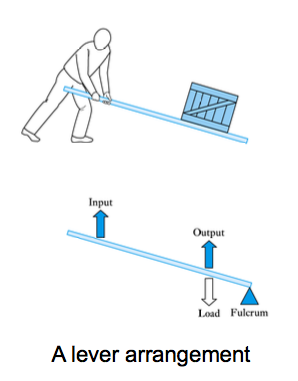
- Non-electronic amplifiers – Levers
● Example shown on the right is a force amplifier, but a displacement attenuator
● Reversing the position of the input and output would produce a force attenuator but a displacement amplifier
● This is an example of a non-inverting amplifier (since the input and output are in the same direction)
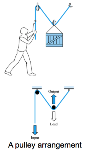
Non-electronic amplifiers – Pulleys
● Example shown right is a force amplifier, but a displacement attenuator
● This is an example of an inverting amplifier (since the input and output are in opposite directions) but other pulley arrangements can be non-inverting
-
- Passive and active amplifiers
- Levers and pulleys are examples of passive amplifiers since they have no external energy source
● In such amplifiers the power delivered at the output must be less than (or equal to) that absorbed at the input
Some amplifiers are not passive but are active amplifiers in that they have an external source of power
● In such amplifiers the output can deliver more power than is absorbed at the input
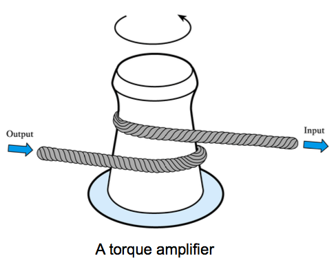
Non-electronic active amplifiers
– an example is the torque amplifier shown here
- Electronic amplifiers
- ● Can be passive (e.g. a transformer) but most are active
● We will concentrate on active electronic amplifiers
– take power from a power supply
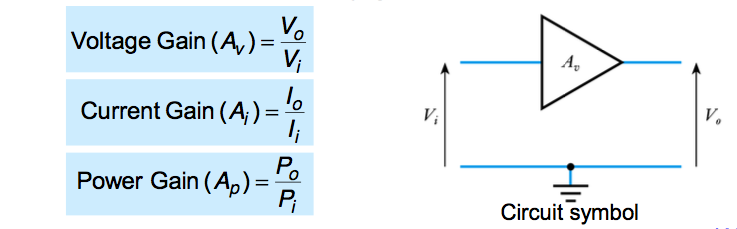
– amplification described by gain
-
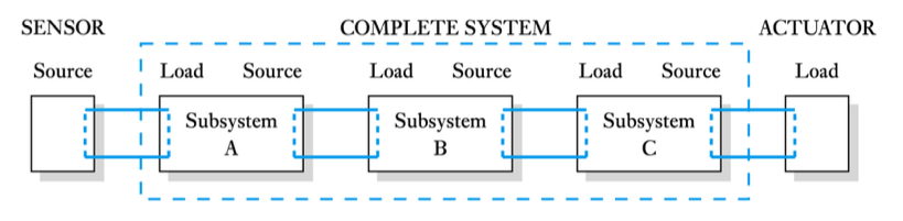
- Sources and loads
- An ideal voltage amplifier would produce an output determined only by the input voltage and its gain.
– irrespective of the nature of the source and the load
– in real amplifiers this is not the case
– the output voltage is affected by loading
- Modelling sources and loads
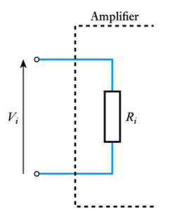
- Modelling the input of an amplifier
– the input can often be adequately modelled by a simple resistor
– the input resistance
Modelling the output of a circuit
– all real voltage sources have an output resistance – for example, a battery can be represented by an ideal voltage source and a series resistance representing its output resistance
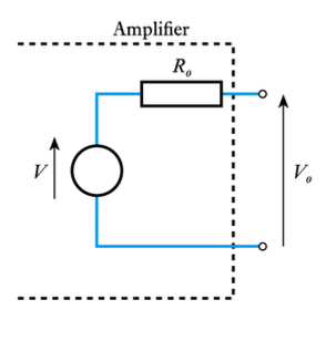
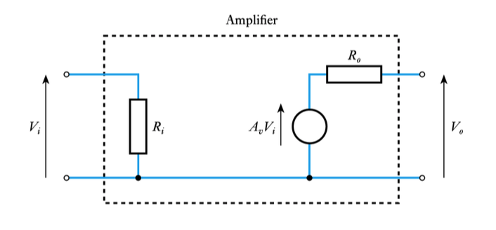
Modelling the output of an amplifier
– Similarly, the output of an amplifier can be modelled by an ideal voltage source and an output resistance.
– This is an example of a Thévenin equivalent circuit
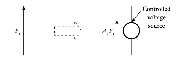
Modelling the gain of an amplifier
– can be modelled by a controlled voltage source
– the voltage produced by the source is determined by the input voltage to the circuit
-
- Equivalent circuit of an amplifier
- Having modelled the input, the output and the gain, we can now model the entire amplifier
Watch The Video 📹
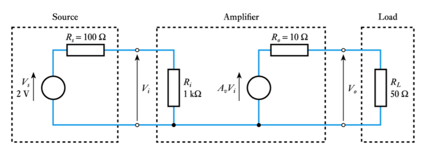
- The use of an equivalent circuit (see Example 14.1 in the course text):
Example: An amplifier has a voltage gain of 10, an input resistance of 1 kΩ and an output resistance of 10Ω . The amplifier is connected to a sensor that produces a voltage of 2 V and has an output resistance of 100Ω , and to a load of 50Ω .
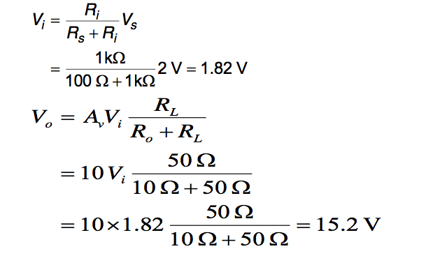
What will be the output voltage of the amplifier (that is, the voltage across the load resistance)?- We start by constructing an equivalent circuit of the amplifier, the source and the load
From this we can calculate the output voltage:
The voltage gain of the circuit in the previous example is given by:
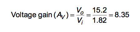
– note that this is considerably less than the stated gain of the amplifier (which is 10)
– this is due to loading effects
– the gain of the amplifier in isolation is its unloaded voltage gain
An ideal voltage amplifier would not suffer from loading
– it would have Ri = ∞ and Ro =0
– consider the effect on the previous example
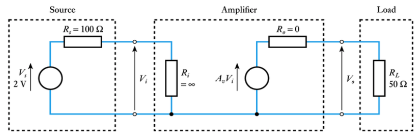
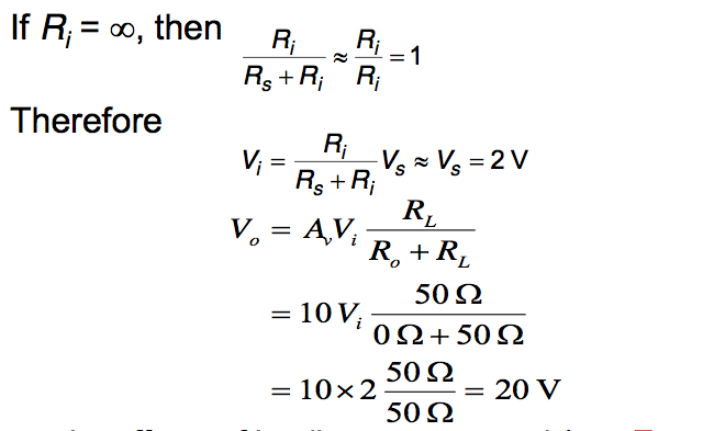
– the effects of loading are removed (see Example 14.3) -
- Output power
- The output power Po is that dissipated in the load resistor
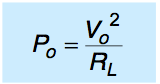
Power transfer is at a maximum when RL = Ro – maximum power theorem
– choosing a load to maximize power transfer is called matching
– often voltage gain is more important than power transfer
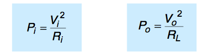
- Power gain
- Power gain is the ratio of the power supplied to the load to that absorbed at the input
Watch The Video 📹
For numerical example see Example 14.5 in set text
- Frequency response and bandwidth
- All real amplifiers have limits to the range of frequencies over which they can be used
The gain of a circuit in its normal operating range is termed its mid-band gain
The gain of all amplifiers falls at high frequencies
– characteristic defined by the half-power point
– gain falls to 1/√ 2 = 0.707 times the mid-band gain
– this occurs at the cut-off frequency
In some amplifiers gain also falls at low frequencies
– these are AC coupled amplifiers
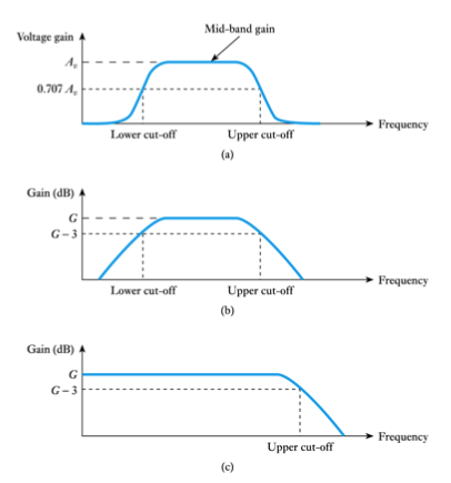
(a) shows an AC coupled amplifier
(b) shows the same amplifier – with gain in dBs
(c) shows a DC coupled amplifier – the gain is constant down to DC
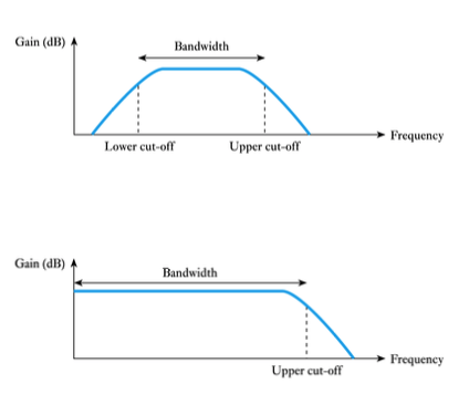
The bandwidth is the difference between the upper and lower cut-off frequencies ...
... or the difference between the upper-cut-off frequency and zero in a DC coupled amplifier -
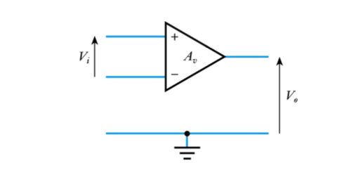
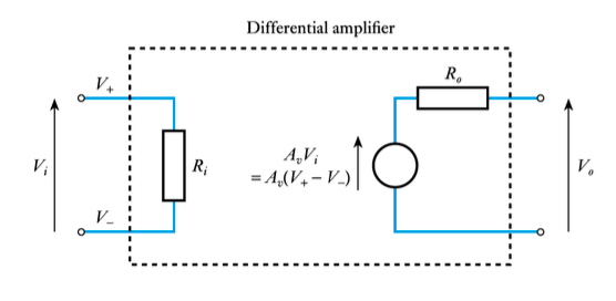
- Differential amplifiers
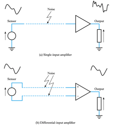
- Differential amplifiers have two inputs and amplify the voltage difference between them
– Inputs are called the non-inverting input (labelled +) and the inverting input (labelled –)
Watch The Video 📹
- An example of the use of a differential amplifier
Equivalent circuit of a differential amplifier
– one of the commonest forms of differential amplifier is the operational amplifier
– discussed in later lectures
-
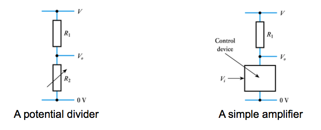
- Simple amplifiers
- Operational amplifiers are relatively complex circuits.
Amplifiers can also be formed using a ‘control device’
– circuit is similar to a potential divider with one resistor replaced with a ‘control device’ typically a transistor
- Key points
- ● Amplification forms part of most electronic systems
● Amplifiers may be active or passive
● Equivalent circuits are useful when investigating the interaction between circuits
● The gain of all amplifiers falls at high frequencies
● The gain of some amplifiers falls at low frequencies
● Differential amplifiers take as their input the difference between two input signals
● Some amplifiers are very simple in construction
-
- Feedback systems
Watch The Video 📹
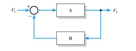
- A generalised feedback system
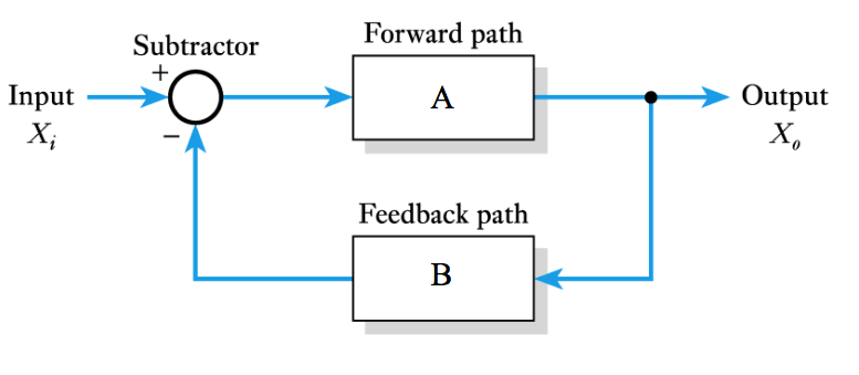
By inspection of diagram we can add values
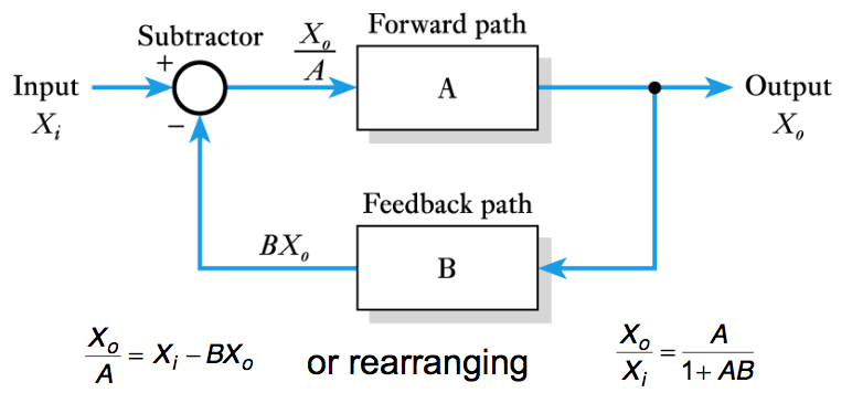
- Thus
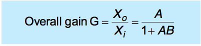
This is the transfer function of the arrangement
Terminology:
● A is also known as the open-loop gain
● G is the overall or closed-loop gain
- Effects of the product AB
– If AB is negative
● If AB is negative and less than 1, (1 + AB) < 1
● In this situation G > A and we have positive feedback
- – If AB is positive
● If AB is positive then (1 + AB) > 1
● In this situation G < A and we have negative feedback
● If AB is positive and AB >>1
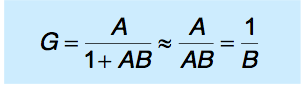
– gain is independent of the gain of the forward path A -
- Negative feedback
Watch The Video 📹
- Negative feedback can be applied in many ways
– Xi and Xo could be temperatures, pressures, etc.
– here we are mainly interested in voltages and currents
Is particularly important in overcoming variability
– all active devices suffer from variability
● their gain and other characteristics vary with temperature and between devices
– we noted above that using negative feedback we can produce an arrangement where the gain is independent of the gain of the forward path
● this gives us a way of overcoming problems of variability
- Negative feedback – an example
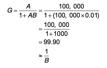
Consider the following example (Example 15.1 in text) Example: Design an arrangement with a stable voltage gain of 100 using a high-gain active amplifier. Determine the effect on the overall gain of the circuit if the voltage gain of the active amplifier varies from 100,000 to 200,000.
We will base our design on our standard feedback arrangement
We will use our active amplifier for A and a stable feedback arrangement for B
Since we require an overall gain of 100 and
we will use B = 1/100 or 0.01
- Now consider the gain of the circuit when the gain of the active amplifier A is 100,000
- Now consider the gain of the circuit when the gain of the active amplifier A is 200,000
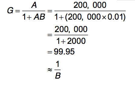
Note that a change in the gain of the active amplifier of 100% causes a change in the overall gain of just 0.05 %.
Thus, the use of negative feedback makes the gain largely independent of the gain of the active amplifier.
However, it does require that B is stable.
– fortunately, B can be based on stable passive components -
- The effects of negative feedback
- Effects on gain
– negative feedback produces a gain given by
– there, feedback reduces the gain by a factor of 1 + AB
– this is the price we pay for the beneficial effects of negative feedback
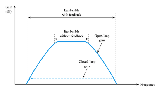 Effects on frequency response
– from earlier lectures we know that all amplifiers have a limited frequency response and bandwidth
– with feedback we make the overall gain largely independent of the gain of the active amplifier
– this has the effect of increasing the bandwidth, since the gain of the feedback amplifier remains constant as the gain of the active amplifier falls
– however, when the open-loop gain is no longer much greater than the closed-loop gain the overall gain falls
– therefore the bandwidth increases as the gain is reduced with feedback
– in some cases the gain x bandwidth = constant
Effects on stability
– from earlier we know that
– so far we have assumed that A and B are positive real numbers
– real amplifiers produce phase shifts at some frequencies
– a phase shift of 180 represents an inversion of the gain
– this will turn negative feedback into positive feedback
– therefore, feedback has implication for stability
– we will return to look at stability in later lectures
- Key points
- Feedback is used in almost all automatic control systems
Feedback can be either negative or positive
If the gain of the forward path is A, the gain of the feedback path is B and the feedback is subtracted from the input then
If AB is positive and much greater than 1, then G ≈ 1/B
Negative feedback can be used to overcome problems of variability within active amplifiers
Negative feedback can be used to increase bandwidth, and to improve other circuit characteristics -
-
-
- title
- title