03
-
- Introduction
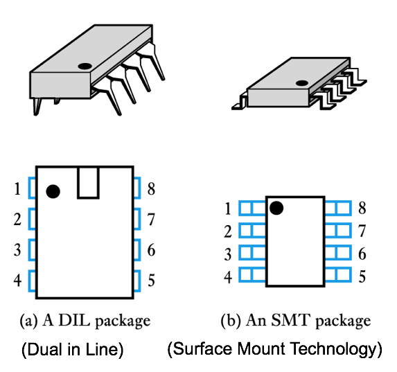
- ● Operational amplifiers (op-amps) are among the most widely used building blocks in electronics
– they are integrated circuits (ICs)
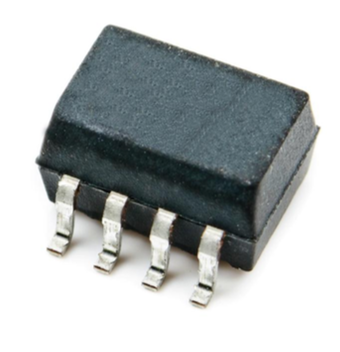
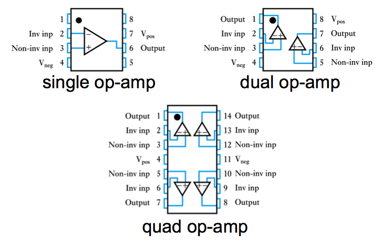
● often DIL or SMT packages
- Operational amplifiers
 ● Introduction
● An ideal operational amplifier
● Basic operational amplifier circuits
● Some other useful circuits
● Real operational amplifiers
● Selecting component values
● Feedback on op-amp circuits
-
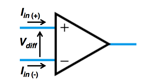
- Op-amp Symbol
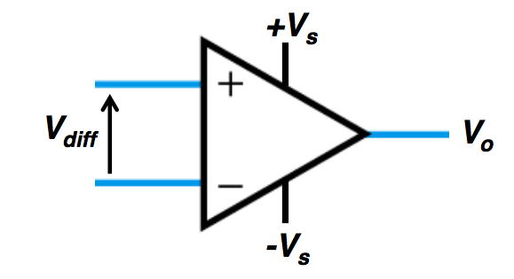
● The op-amp is essentially a very high gain differential amplifier
vo = AVdiff = A [Vin(+) - Vin(-) ]
A > 100,000
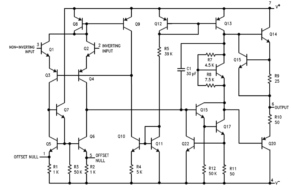
- Op-amp internal circuit (LM741)
- Op-amps and Feedback
- ● Op-amps are NOT used to amplify a signal applied directly to the input by hundreds of thousands of times
● They are used with NEGATIVE FEEDBACK
● This reduces the gain to useful levels in a controllable way
● Negative feedback also results in improved amplifier characteristics like higher input resistance, lower output resistance, better temperature stability, etc.
● We will come back to feedback later
● A single package will often contain several op-amps
-
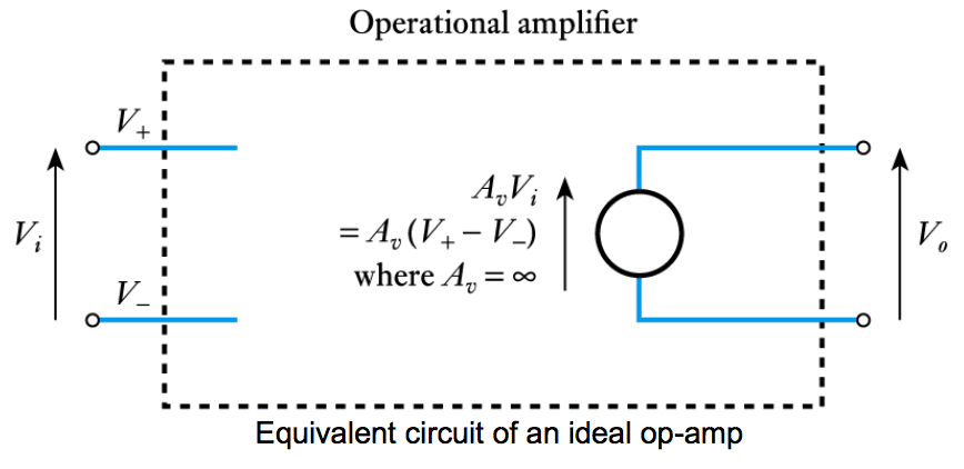
- An ideal operational amplifier
- ● An ideal op-amp would be an ideal voltage amplifier and would have:
Av = ∞, Ri = ∞ and Ro = 0
● In practice we often use standard ‘cookbook’ circuits and select component values to suit our needs
● In analysing these circuits we normally assume the use of ideal op-amps
– in demanding applications we may need to investigate the appropriateness of this assumption
– however the use of ideal components makes the analysis of these circuits very straight forward
- The two Golden Rules for ideal op-amps
- ● Golden Rules of ideal op-amp circuit analysis (with negative feedback)
1) Vdiff = V(+) - V(-) ≈ 0 (virtual short circuit)
2) Iin (+) ≈ Iin (-) ≈ 0 (infinite input resistance)
-
- Basic operational amplifier circuits
Watch the video. 📹
- ● Inverting and non-inverting amplifiers
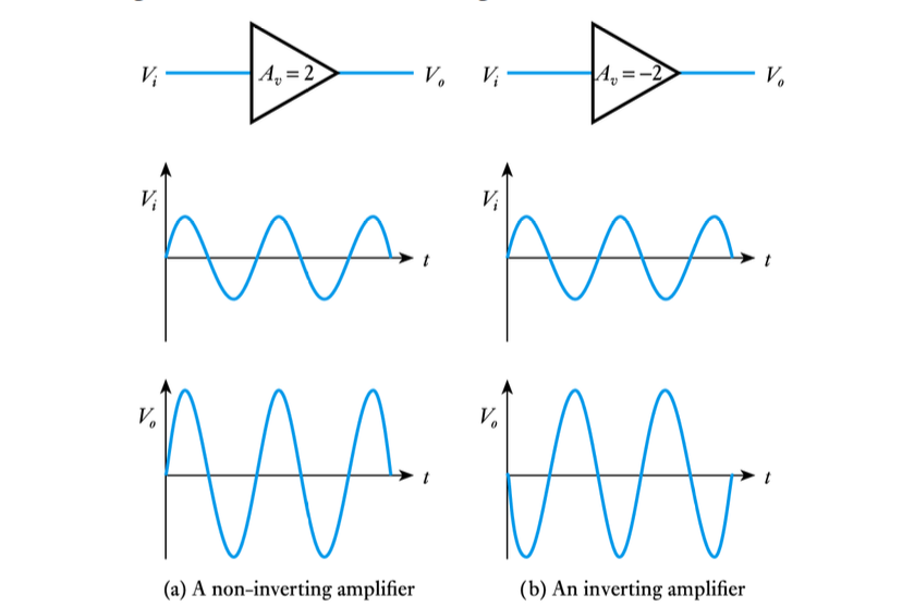
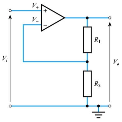
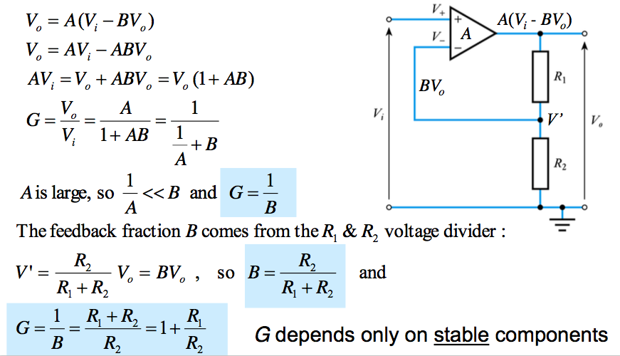
● A non-inverting amplifier
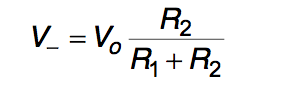
Analysis From Golden Rule No. 1 (Vdiff = 0)
V_ = V+ =Vi
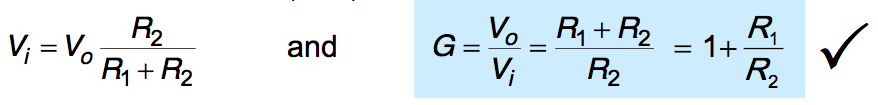
Golden Rule No. 2 means that we also have
and hence, since V_ = V+ = Vi
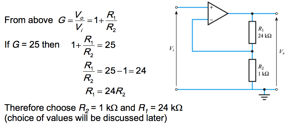
Example (see Example 16.1 in the course text)
Design a non-inverting amplifier with a gain of 25
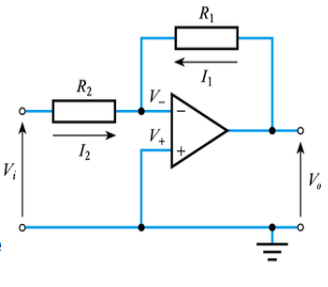 ● An inverting amplifier
Analysis
Since the gain is assumed infinite, if Vo is finite the op-amp input voltage must be zero (golden rule No. 1). Hence
V_ = V+ = 0
Since the input resistance of the op-amp is ∞, its input current must be zero (rule 2), and hence I1 = -I2
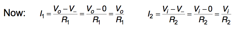
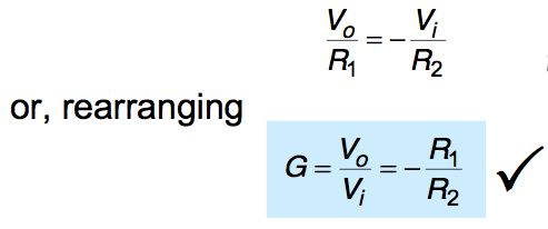
Therefore, since I1 = -I2
Here V_ is held at zero volts by the operation of the circuit, hence the circuit is known as a virtual earth circuit.
Example (see Example 16.2 in the course text) Design an inverting amplifier with a gain of –25
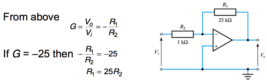
Therefore choose R2 = 1 kΩ and R1 = 25 kΩ (we will consider the choice of values later) -
- Some other useful circuits
Watch the video. 📹
- ● In addition to simple amplifiers, op-amps can also be used in a range of other circuit
● The next few slides show a few examples of op-amp circuits for a range of purposes
● The analysis of these circuits is similar to that of the non-inverting and inverting amplifiers but (in most cases) this is not included here
● For more details of these circuits see the relevant section of the course text (as shown on the slides)
● A unity-gain buffer amplifier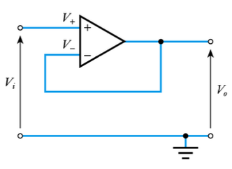
Analysis
This is a special case of the non-inverting amplifier with R1 = 0 and R2 = ∞
Hence
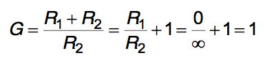
Thus the circuit has a gain of unity
At first sight this might not seem like a very useful circuit, however, it has a high input resistance and a low output resistance and is therefore useful as a buffer amplifier
- Using a unity-gain buffer amplifier
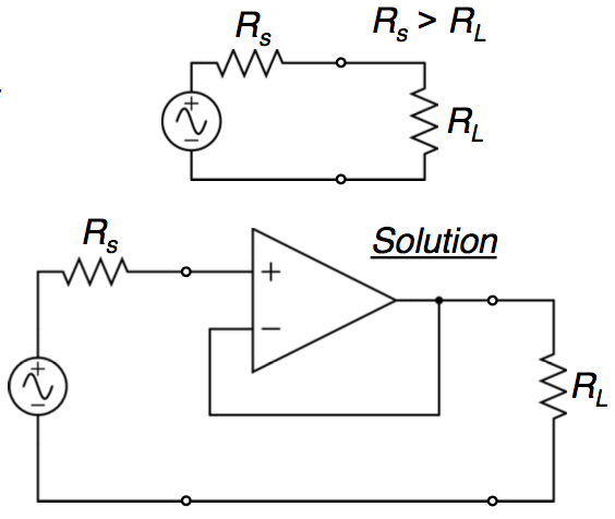
- ● Ideally when you connect a signal source to a load you want the internal resistance of the source to be small compared to the load resistance (Rs ≪ RL) to avoid the loading effect
● If that condition is not met, you can prevent the loading effect by inserting a unity- gain buffer amplifier
● Then the generator will see a high load resistance (the buffer Rin) and the load will see a low source resistance (the buffer Ro)
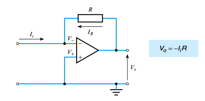
- ● A current to voltage converter
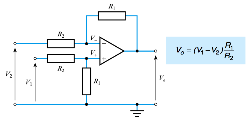
- ● A differential amplifier (or subtractor)
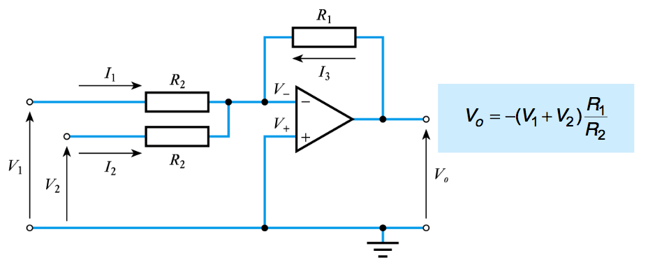
- ● An inverting summing amplifier
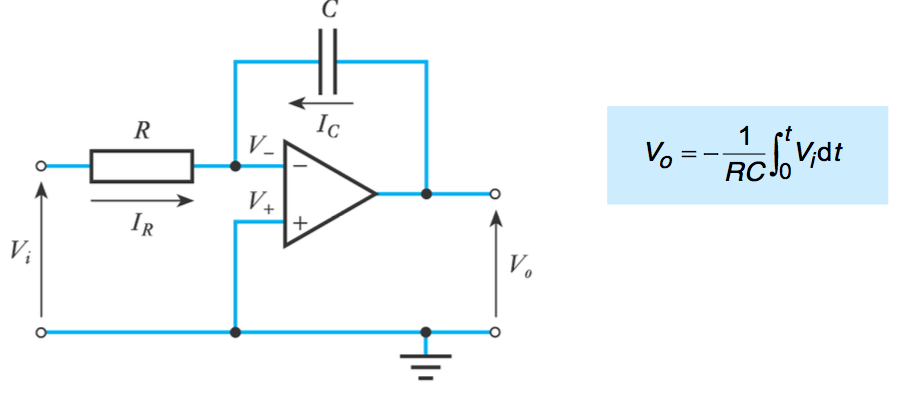
- ● An integrator
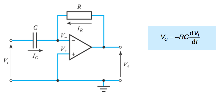
- ● A differentiator
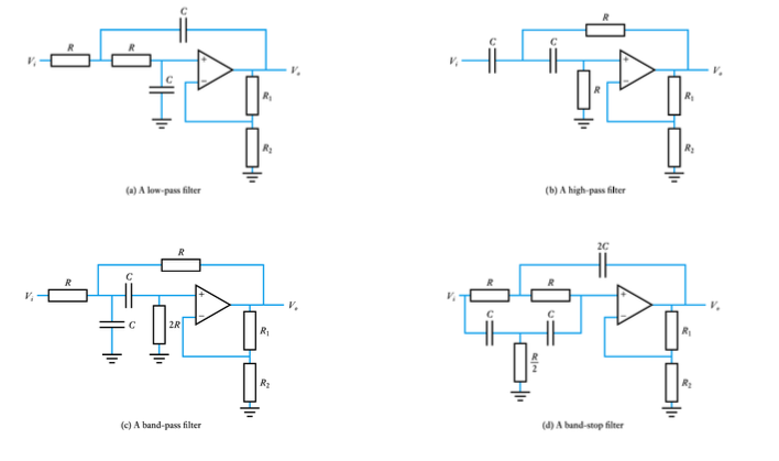
- ● Active filters
-
- ● Supply voltage range
– a typical arrangement would use supply voltages of +15V and – 15V, but a wide range of supply voltages is usually possible
– the 741 can use voltages in the range +5 to +18 V
– some devices allow voltages up to +30 V or more
– others, designed for low voltages, may use +1.5 V
– many op-amps permit single voltage supply operation, typically in the range 4 to 30 V
● Common-mode rejection ratio
– an ideal op-amp would not respond to common-mode signals.
– real amplifiers do respond to some extent
– the common-mode rejection ratio (CMRR) is the ratio of the response produced by a differential-mode signal to that produced by a common-mode signal
– typical values for CMRR might be in the range 80 to 120 dB
• 741 has a CMRR of about 90 dB
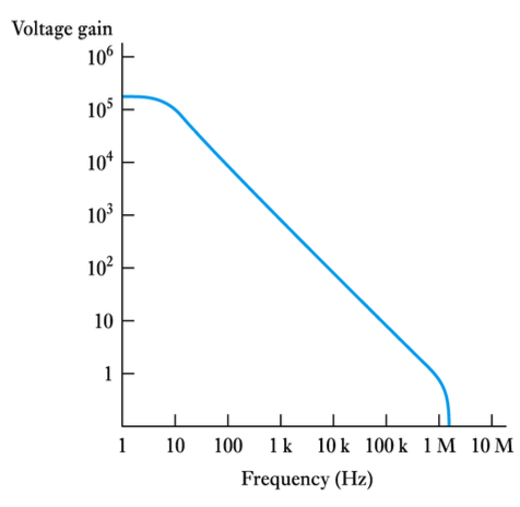
● Frequency response
– typical 741 frequency response is shown here
– upper cut-off frequency is a few hertz
– frequency range generally described by the unity-gain bandwidth
– high-speed devices may operate up to several gigahertz
- Real operational amplifiers
- ● So far we have assumed the use of ideal op-amps – these have Av = ∞, Ri = ∞ and Ro = 0
● Real components do not have these ideal characteristics (though in many cases they approximate to them)
● In this section we will look at the characteristics of typical devices
– perhaps the most widely used general purpose op- amp is the 741
● Voltage gain
– typical gain of an operational amplifier might be 100 – 140 dB (voltage gain of 105 – 106)
– 741 has a typical gain of 106 dB (2 x 10⁵)
– high gain devices might have a gain of 160 dB (108)
– while not infinite, the gain of most op-amps is ‘high-enough’
– however, gain varies between devices and with temperature
● Input resistance
– typical input resistance of a 741 is 2 MΩ
– very variable, for a 741 it can be as low as 300 kΩ
– the above value is typical for devices based on bipolar transistors
– op-amps based on field-effect transistors generally have a much higher input resistance – perhaps 1012 Ω
● Output resistance
– typical output resistance of a 741 is 75 Ω
– again very variable
– often of more importance, is the maximum output current
– the 741 will supply 20 mA
– high-power devices may supply an amp or more
- ● Supply voltage range
-
- Non-inverting amplifier revisited
- Selecting component values
- ● Our analysis assumed the use of an ideal op-amp
● When using real components we need to ensure that our assumptions are valid
● In general this will be true if we:
– limit the gain of our circuit to much less than the open-loop gain of our op-amp
– choose external resistors that are small compared with the input resistance of the op-amp
– choose external resistors that are large compared with the output resistance of the op-amp.
● Generally we use resistors in the range 1 to 100 kΩ
- Negative feedback
-
- Effects of feedback on op-amp circuits
Watch the video 📹
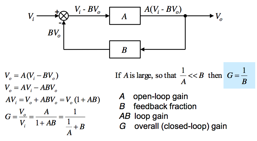
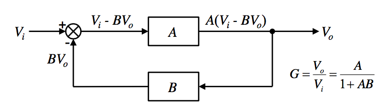
- ● Effects of feedback on the gain
– negative feedback reduces gain from A to A/(1 + AB)
– in return for this loss of gain we get consistency, provided that the open-loop gain is much greater than the closed-loop gain (that is, A >> 1/B)
– using negative feedback, standard cookbook circuits can be used – greatly simplifying the design
– these can be analysed without a detailed knowledge of the op-amp itself
– (1 + AB) is called the desensitivity
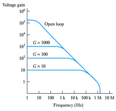
● Effects of feedback on frequency response
– as the gain is reduced the bandwidth is increased
– gain x bandwidth ≈ constant
• since gain is reduced by (1 + AB) bandwidth is increased by (1 + AB)
– for a 741,
gain x bandwidth ≈ 106
• if gain = 1000 BW ≈ 1000 Hz
• if gain = 100 BW ≈ 10,000 Hz
Watch the video 📹
● Effects of feedback on input and output resistance
– input/output resistance can be increased or decreased depending on how feedback is used
● in each case the resistance is changed by a factor of (1 + AB)
Example
– if an op-amp with a gain of 2 x 10⁵ is used to produce an amplifier with a gain of 100 then:
A = 2 x 10⁵
B = 1/G = 0.01
(1 + AB) = (1 + 2000) ≈ 2000
● Example (see Example 16.5 in the course text)
– determine the input and output resistance of the following circuit assuming op-amp is a 741
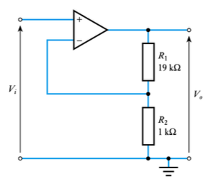 Open-loop gain (A) of a 741 is 2 x 10⁵.
Closed-loop gain (1/B) is 20, B = 1/20 = 0.05 (1 + AB) = (1 + 2 x 105 x 0.05) = 104.
Feedback senses output voltage therefore it reduces output resistance of op-amp (75 = Ω) by 104 to give 7.5 mΩ.
Feedback subtracts a voltage from the input, therefore it increases the input resistance of the op-amp (2 MΩ) by 104 to give 20 GΩ.
● Example (see Example 16.6 in the course text)
– determine the input and output resistance of the following circuit assuming op-amp is a 741
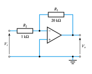 Open-loop gain (A) of a 741 is 2 x 10⁵
Closed-loop gain (1/B) is 20, B = 1/20 = 0.05 (1 + AB) = (1 + 2 x 105 = 0.05) = 104
Feedback senses output voltage therefore, it reduces output resistance of op-amp (75 Ω) by 104 to give 7.5 mΩ
Feedback subtracts a current from the input, therefore it decreases the input resistance. In this case the input sees R2 to a virtual earth, therefore the input resistance is 1 kΩ
-
- Feedback and Stability
● Op-amp gain (both its magnitude and phase) changes with frequency
● If at some frequency the gain is such that AB = -1, then G will become infinite and the output will oscillate at that frequency even with no input signal: the circuit will be unstable
● COMPENSATED op-amps are designed to prevent this from ever happening and are unconditionally stable
-
- Key points
- ● Operational amplifiers are among the most widely used building blocks in electronic circuits
● An ideal operational amplifier would have infinite voltage gain, infinite input resistance and zero output resistance
● Designers often make use of cookbook circuits
● Real op-amps have several non-ideal characteristics However, if we choose components appropriately this should not affect the operation of our circuits
● Feedback allows us to increase bandwidth by trading gain against bandwidth
● Feedback also allows us to alter other circuit characteristics
-
-
-
- right
- left