04
-
The first Law: Control Volumes
- The first law is discussed for closed systems in Chapter 3. In this Chapter, we extend the conservation of energy to systems that involve mass flow across their boundaries, control volumes.
- Any arbitrary region in space can be selected as control volume. There are no concrete rules for the selection of control volumes. The boundary of control volume is called a control surface.
4.1 Conservation of Mass
- Like energy, mass is a conserved property, and it cannot be created or destroyed. Mass and energy can be converted to each other according to Einstein’s formula: E = mc2, where c is the speed of light. However, except for nuclear reactions, the conservation of mass principle holds for all processes.
- For a control volume undergoing a process, the conservation of mass can be
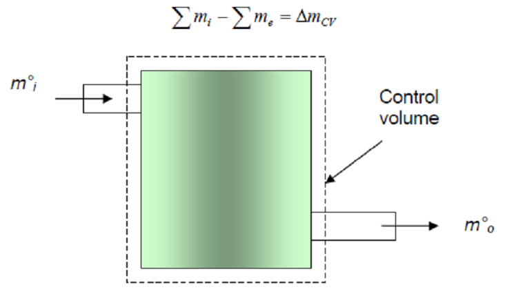
- Fig. 4-1: Conservation of mass principle for a CV.
- The conservation of mass can also be expressed in the rate form:
- \sum \dot{m}_i - \sum \dot{m}_e = dm_{cv} / dt
- The amount of mass flowing through a cross section per unit time is called the mass flow rate and is denoted by \dot{m} . The mass flow rate through a differential area dA is:
- d\dot{m} = p \times C_n \times dA
- Mass flow through a cross-sectional area per unit time is called the mass flow rate \dot{m}. Note the dot over the mass symbol indicates a time rate of change. It is expressed as
- \dot{m} = \int pC_ndA \qquad \qquad \textrm{(kg/s)}
- Where C is the velocity component normal to dA.
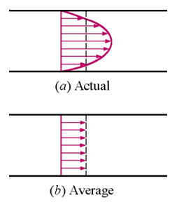
- Assuming one-dimensional flow, a uniform (averaged or bulk) velocity can be defined
- \dot{m} = p \times A \times \overline{C} \qquad \qquad \textrm{(kg/s)}
- If the fluid density and velocity are constant over the flow cross-sectional area, the mass flow rate is
- \dot{m} = p \times A \times \overline{C} = \frac{\overline{C}A}{v} \qquad \qquad \textrm{(kg/s)}
- where p is the density, kg/m3 ( = 1/v), A is the cross-sectional area, m2; and \overline{C} is the average fluid velocity normal to the area, m/s.
- The fluid volume flowing through a cross-section per unit time is called the volume flow rate \dot{V}. The volume flow rate is given by integrating the product of the velocity normal to the flow area and the differential flow area over the flow area. If the velocity over the flow area is a constant, the volume flow rate is given by
- \dot{V} = A \times \overline{C} \qquad \qquad (m^3/s)
- The mass and volume flow rate are related by
- \dot{m} = p\dot{V} \qquad \qquad \textrm{(kg/s)}
Example: 4.1
- Air at 100 kPa, 50oC, flows through a pipe with a volume flow rate of 40 m3/min. Find the mass flow rate through the pipe, in kg/s.
- Assume air to be an ideal gas, so v = \frac{RT}{P} = 0.287 \frac{kJ}{kg \cdot K} \frac{(50 + 273)K}{100kPa} \frac{m^3kPa}{kJ}
- = 0.9270 \frac{m^3}{kg}
- \dot{m} \frac{\dot{V}}{v}= \frac{40m^3/min}{0.9270m^3/kg}\frac{1 min}{60s}
- = 0.719 \frac{kg}{s}
-
4.2 Conservation of Energy
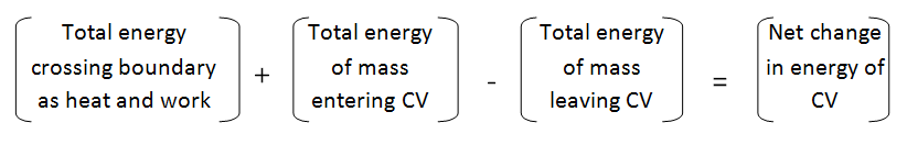
- For control volumes, an additional mechanism can change the energy of a system: mass flow in and out of the control volume. Therefore, the conservation of energy for a control volume undergoing a process can be expressed as
- Q-W = \sum E_{in, mass} + \sum E_{out, mass} =\Delta E_{CV}
- This equation is applicable to any control volume undergoing any process. This equation can also be expressed in rate form:
- \dot{Q}- \dot{W} = \sum dE_{in, mass} / dt + \sum dE_{out, mass}dt = \DeltaE_{CV}/dt
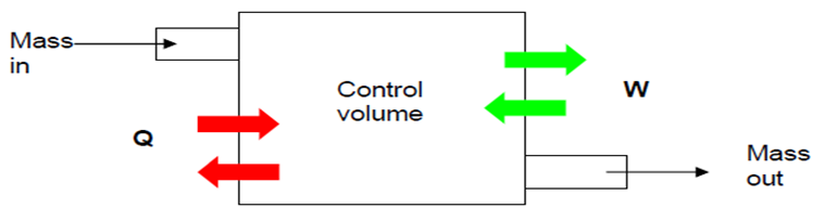
- Fig. 4-2: Energy content of CV can be changed by mass flow in/out and heat and work interactions.
- Work flow: is the energy that required to push fluid into or out of a control volume. Consider an imaginary piston Figure 4-3 (that push the fluid to CV) where the fluid pressure is P and the cross sectional area is A. The force acting on the piston is F = PA.
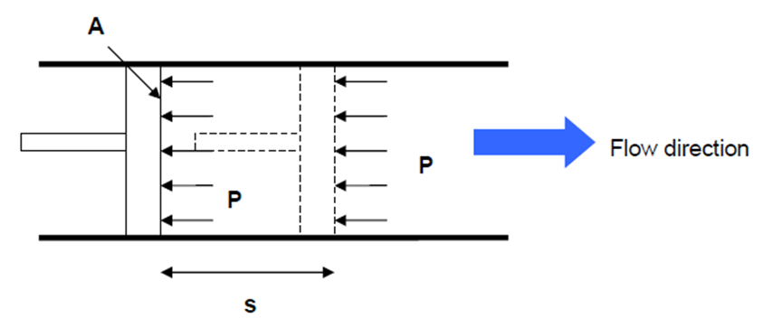
- Fig. 4-3: schematic for flow work.
- The work done in pushing the fluid is:
- W_{flow} = F \times s = PA \times s = P \times V \qquad \qquad \textrm{(kJ)}
- or in a unit basis,
- W_{flow} = \frac{W_{flow}}{m} = P \times v \qquad \qquad \textrm{(kJ/kg)}
- Note that the flow work is expressed in terms of properties.
- The flow work can also be written as a rate equation.
- The fluid entering or leaving a control volume possesses an additional form of energy (flow energy Pv). Therefore, the total energy of a flowing fluid on a unit mass basis becomes:
- Q - W = (\frac{1}{2}mc^2_2 - \frac{1}{2}mc^2_1) + (mgz_2 - mgz_1) + (U_2 + P_2V_2)-(P_2V_2 - P_1V_1)
- Rearrange Q - W = (\frac{1}{2}mc^2_2 - \frac{1}{2}mc^2_1) + (mgz_2 - mgz_1) + (U_2 + P_2V_2) - (U_1 + P_1V_1)
- Recall that enthalpy is defined as: H = U + PV. Therefore, the above equation becomes:
- Q - W = (\frac{1}{2}mc^2_2 - \frac{1}{2}mc^2_1) + (mgz_2 - mgz_1) + (H_2 - H_1)
- Remember that q=Q/m ; w = W/m and h=H/m
- q - w = (h_2 - h_1) + g(z_2 - z_1) + \frac{1}{2}(c^2_2 - c^2_1)
- Each term in above equation is in units of kJ/kg
- Multiply both sides of the equation by \dot{m} (mass flow rate)
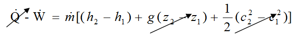
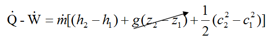
- \dot{Q} - \dot{W} = \dot{m}[(h_2 - h_1) + g (z_2 - z_1) + \frac{1}{2}(c^2_2 - c^2_1)]
- Each term in above equation is in units of kW (kilowatt)
-
4.3 Steady-State Flow Process
- A process during which a fluid flows through a control volume steadily is called steady-state process. A large number of devices such as turbines, compressors, and nozzles operates under the same conditions for a long time and can be modelled (classified) as steady-flow devices.
- The term steady implies no change with time. The term uniform implies no change with location over a specified region.
- A steady flow is characterized by the following:
- 1- No properties within the CV change with time. Thus, volume, mass, and energy of CV remain constant. As a result, the boundary work is zero. Also, total mass entering the CV must be equal to total mass leaving CV.
- 2- No properties change at the boundary of the CV with time. It means that the mass flow rate and the properties of the fluid at an opening must remain constant during a steady flow.
- 3- The heat and mass interactions between the CV and its surroundings do not change with time. Using the above observation, the conservation of energy principle for a general steady-flow system with multiple inlets and exits can be written as:
- \dot{Q} - \dot{W} = \sum \dot{m}_e [(h_e + \frac{1}{2}c^2_e + gz_e)] - \sum \dot{m}_i [(h_i + \frac{1}{2}c^2_i + gz_i)]
-
4.4 Applications of Steady Flow Energy Equation:
4.4.1 Turbines and Compressors
- In steam, gas, or hydroelectric power plants, the device that derives the electric generator is turbine. The work of turbine is positive since it is done by the fluid. Compressors, pumps, and fans are devices used to increase the pressure of the fluid. Work is supplied to these devices, thus the work term is negative.
- Turbine: produce work by expanding a gas/steam to a lower pressure, density, and enthalpy.
- Fluid does work on blades which are attached to a shaft Figure 4-4.
- Shaft often attached to a generator or compressor
- Steam, gas, hydroelectric
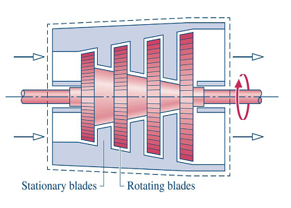
- Figure 4-4: Turbine
- Compressor: increase pressure, density, and enthalpy of a gas/steam through a work input.
- A variety of types: bladed (radial or axial), piston cylinder, …
- Work input from a shaft connected to a motor, turbine, etc.
- Pumps for liquids, fans for small pressure rises
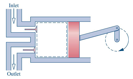
- Figure 4-5: Compressor
- Common assumptions for turbines and compressors: The system is adiabatic i.e. \dot{Q}=0
- Kinetic energy changes are usually small compared to enthalpy changes and hence the kinetic and potential energies changes are normally neglected (unless otherwise stated) ΔPE = ΔKE = 0.
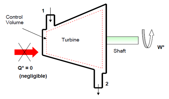
- Figure 4-6: Schematic for turbine.
- Apply the steady flow energy equation between points 1 & 2 taking in consideration the above assumptions
- Thus - \dot{W} = \dot{m}(h_2 - h_1) \qquad \qquad \textrm{kW}
- - w = (h_2 - h_1) \qquad \qquad \textrm{kJ/kg}
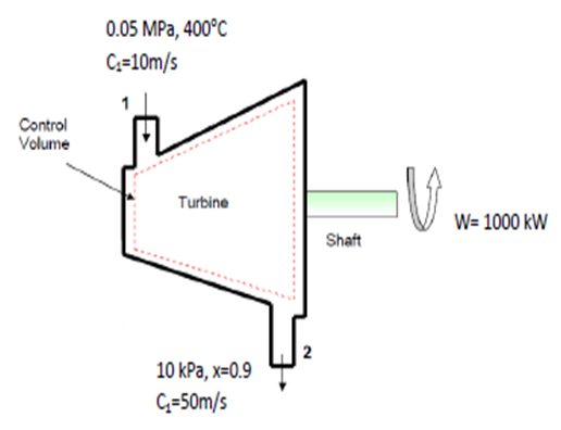
Example 4-2: Turbine
- Steam enters a turbine at steady state with a mass flow rate of 4600 kg/h. The turbine develops a power output of 1000 kW. At the inlet the pressure is 0.05 MPa, the temperature is 400 °C, and the velocity is 10 m/s. At the exit, the pressure is 10 kPa, the quality is 0.9, and the velocity is 50 m/s. Calculate the rate of heat transfer between the turbine and surroundings, in kW.
- Assumptions: Steady-state operation and the change in potential energy is negligible.
- The energy balance for the turbine is:
- \dot{Q} = \dot{W} + \dot{m}[(h_2 - h_1) + \frac{1}{2}(c^2_2 - c^2_1)] \rbrace
- State 1: at turbine entry
- Since T1 Tsat @ 5 bar, thus the steam is superheated at entry to turbine.
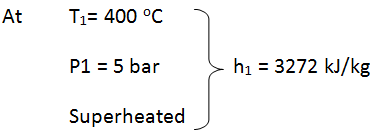
- State 2: at the exit of turbine
- Since a dryness fraction is given, thus the steam is wet mixture at exit of the turbine.
- h_2 = h_f + x(h_g - h_f) \qquad \text{or} \qquad h_2 = h_f + x(f_{fg})
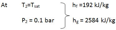
- h_2 = 192 + 0.9(2392) = 2344 .8 \qquad \textrm{kJ / kg}
- \dot{m} = \frac{4600}{3600} = 1.278 \qquad \textrm{kg / s}
- \dot{Q} = \dot{W} + \dot{m}[(h_2 - h_1) + \frac{1}{2}(c^2_2 - c^2_1)]
- \dot{Q} = 1000 +(1.278)[(2344.8 - 3272) + \frac{1}{2} (50^2 - 10^2) \times 10^{-6}] = - 184.96 \qquad \textrm{kW}
- Note that change in specific kinetic energy is very small. Also \dot{Q} is small compared to \dot{W}. The negative sign in \dot{Q} means that heat transfer is from the system to surroundings.
Example 4-3: Turbine
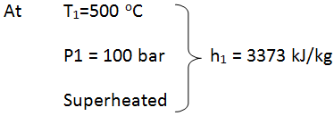
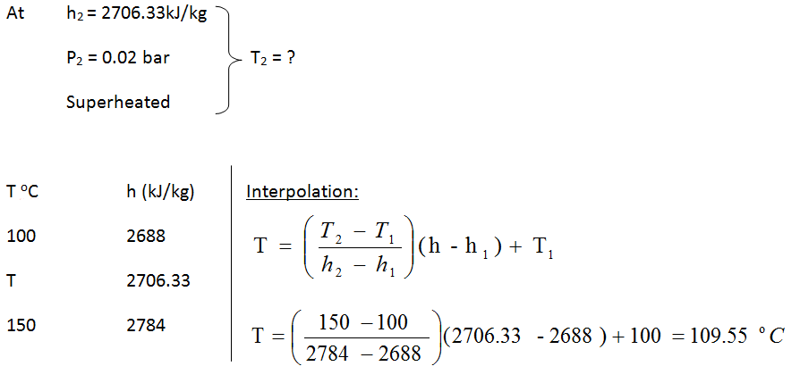
- Steam at 10 MPa, 500 oC enters an adiabatic turbine at 3 kg/s and leaves the turbine at 50 kPa. The turbine produces 2 MW. Neglecting kinetic energy changes determine the temperature of the steam leaving the turbine.
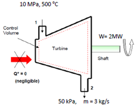
- State 1: at turbine entry
- Since T1 Tsat @ 100 bar, thus the steam is superheated at entry to turbine.
- Since the turbine is adiabatic and neglecting kinetic energy changes, thus
- - \dot{W} = \dot{m}(h_2 - h_1) \rightarrow \dot{W} = \dot{m}(h_1 - h_2)
- h_2 = h_1 = \frac{\dot{W}}{\dot{m}} = 3373 - \frac{2000}{3} = 2706.33 \textrm{kJ/kg}
- State 2: at the exit of turbine
- Since h2 > hg @ 0.05 bar, thus the steam is superheated at exit of the turbine.
Example 4-4
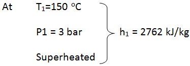
- A fluid enters a turbine at the rate of 14kg/s with an initial pressure and temperature of 3bar and 150oC. Given that the final pressure is 1 bar and the isentropic efficiency of the turbine is 0.85, determine the power developed by the turbine:
- (a) when the working fluid is steam;
- (b) when the working fluid is air. For air take \gamma = 1.4
- (a) Steam
- State 1: at turbine entry
- Since T1 Tsat (133.5oC)@ 3 bar, thus the steam is superheated at entry to turbine.
- State 2: at the exit of turbine
- The process in the turbine is isentropic, thus s1=s2 =7.078 kJ/kg K
- At 1 bar sf =1.303 kJ/kg K and sg = 7.359 kJ/kg K
- Since sf <s2<sg @ 1 bar, thus the steam is a wet mixture at exit of turbine
- x_2 = \frac{s_2 - s_f}{s_g - s_f} = \frac{7.078 - 1.303}{7.359 - 1.303} = 0.954
- h_2 = h_f + x(h_g - h_f)
- h_2 = 417 + 0.954(2675 - 417) = 2572 \qquad \textrm{kJ / kg}
- From the energy equation,
- - \dot{W} = \dot{m}(h_2 - h_1) \rightarrow \dot{W} = \dot{m}(h_1 - h_2)
- \dot{W} = \eta_T \dot{m}(h_1 - h_2) = 0.85 \times 14(2762 - 2572) = 2261 \textrm{kW}
- (b) Air
- Since for an isentropic process
- pv^\gamma = c \qquad \textrm{or} \qquad p_1v_1^\gamma = p_2v_2^\gamma \rightarrow \frac{v_2}{v_1} = \big ( \frac{p_1}{p_2} \big ) ^\frac{1}{\gamma}
- \frac{p_1v_1}{T_1} = \frac{p_2v_2}{T_2} \rightarrow \frac{p_1}{p_2} = \frac{T_1}{T_2}\big(\frac{p_1}{p_2} \big )^\frac{1}{\gamma} \rightarrow \frac{T_1}{T_2} = \big( \frac{p_1}{p_2} \big )^{1- \frac {1}{1}}
- \frac{T_1}{T_2}=\big ( \frac{p_1}{p_2} \big ) ^{\frac{\gamma - 1}{\gamma}} \rightarrow -T_2 = \frac{T_1}{\big (\frac{p_1}{P_2} \big)^{\frac{\gamma - 1}{\gamma}}} = \frac{423}{\big (\frac{3}{1}\big )^{\frac{1.4-1}{1.4}} } = 309K
- \dot{W} = \eta_T\dot{m}C_p(T_1-T_2) = 0.85 \times 14 \times 1.005(423 - 309) = 1363kW
-
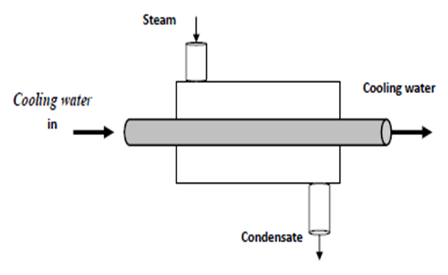
4.4.2 Heat Exchangers (condenser)
- Heat exchangers are devices where two moving fluid streams exchange heat without mixing as shown in Figure 4-7.
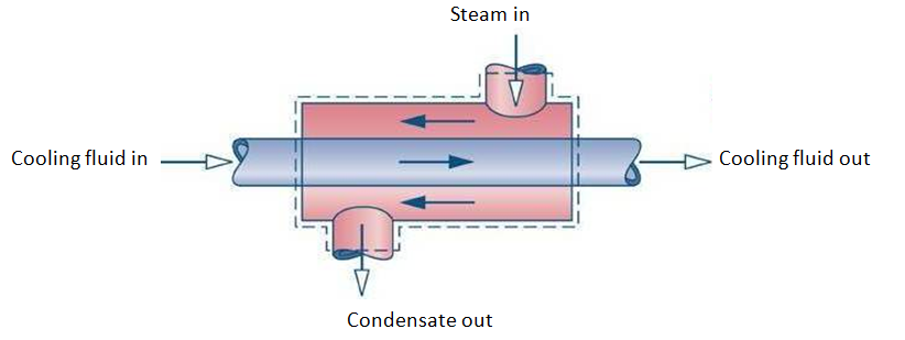
- Figure 4-7: Heat Exchangers (condenser)
- Common assumptions for heat exchangers:
- \dot{W} = 0
- \Delta PE = \Delta KE = 0.
- The mass and energy balance become:
- \dot{m}_1 = \dot{m}_2 \qquad \textrm{and} \qquad \dot{m}_3 = \dot{m}_4 \qquad \dot{m}_3h_3 + \dot{m}_1h_1 = \dot{m}_1h_4 + \dot{m}_1h_2
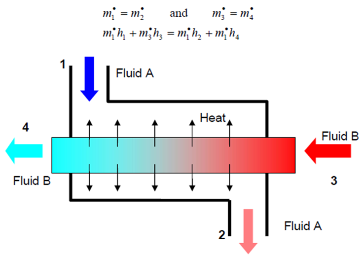
- Figure 4-8: Schematic for heat exchanger.
Example 4-5: Heat exchanger
- Engine oil is to be cooled by water in a condenser. The engine oil enters the condenser with a mass flow rate of 6 kg/min at 1 MPa and 70°C and leaves at 35°C. The cooling water enters at 300 kPa and 15°C and leaves at 25°C. Neglecting any pressure drops; determine a) the mass flow rate of the cooling water required, and b) the heat transfer rate from the engine oil to water.
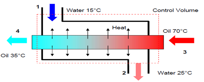
- We choose the entire heat exchanger as our control volume, thus work transfer and heat transfer to the surroundings will be zero. From mass balance:
- \dot{m}_1 = \dot{m}_2 = \dot{m}_w \qquad \textrm{and} \qquad \dot{m}_3 = \dot{m}_4 = \dot{m}_{oil}
- The conservation of energy equation is:
- \dot{Q} - \dot{W} = \sum \dot{m}_e[(h_e + \frac{1}{2}c^2_e + gz_e)] - \sum \dot{m}_i[(h_i + \frac{1}{2}c^2_i + gz_1)]
- \sum \dot{m}_eh_e = \sum \dot{m}_ih_i
- \dot{m}_{oil}h_3 + \dot{m}_wh_1 = \dot{m}_{oil}h_4 + \dot{m}_wh_2
- \dot{m}_w = \frac{h_3 - h_4}{h_2 - h_1}\dot{m}_{oil}
- Assuming constant specific heat for both the oil and water at their average temperature,
- \dot{m}_w = \frac {C_{p,oil}(T_3 - T_4)}{C_{p, w}(T_2 - T_1)}\dot{m}_{oil}
- \dot{m}_w = \frac{2.016(70 - 35)}{4.18(25 - 15)} \times \frac{6}{60}=0.176 kg/s
- To get the rate of heat transfer from one stream to the other perform CV analysis on only the inner-tube (assume inner-stream is hotter than outer stream)
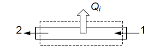
- Again Applying First Law with same assumptions
- 0 = (-\dot{Q}_1) + \dot{m}_i(h_1 - h_2)
- \frac{\dot{Q}_i}{\dot{m}_1}=(h_1 - h_2)
- Since \dot{Q}_i > 0 \rightarrow h_1 > h_2, so T_1 > T_2 (fluid cools down)
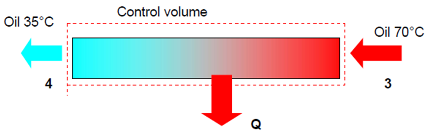
- To determine the heat transfer from the oil to water, choose the following CV. The energy equation becomes:
- \dot{Q}_{oil} = \dot{m}_{oil}\Delta h = \dot{m}_{oil}(h_4 - h_3) = \dot{m}_{oil}C_{p, oil}(T_4 - T_3) = \frac{6}{60}(2.016)(35-70)
- =-7.056kW
Example:4-6
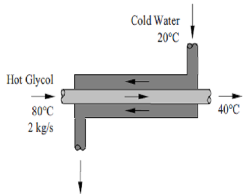
- Ethylene glycol is cooled by water in a heat exchanger. The Ethylene glycol enters the heat exchanger with a mass flow rate of 2 kg/s and 80°C and leaves at 40°C. The cooling water enters at 20°C and leaves at 25°C. Given that the heat exchanger is well-insulated and specific heats of water and ethylene glycol are 4.18 and 2.56 kJ/kg K, determine the rate of heat transfer in the heat exchanger and the mass flow rate of water.
- Assumptions 1 Steady operating conditions exist. 2 The heat exchanger is well-insulated so that heat loss to the surroundings is negligible and this heat transfer from the hot fluid is equal to the heat transfer to the cold fluid. 3 Changes in the kinetic and potential energies of fluid streams are negligible. 4 Fluid properties are constant.
- Properties The specific heat of water and ethylene glycol are given to be 4.18 and 2.56 kJ/kg. °C, respectively.
- Analysis (a) We take the ethylene glycol tubes as the system, which is a control volume. The energy balance for this steady-flow system can be expressed in the rate form as
- \dot{E}_{in} - \dot{E}_{out} = \Delta E_{system} \quad ^{\nearrow0 (steady)} = 0
- First part of equation: Rate of net energy transfer by heat, work, and mass
- Second part of equation: Rate of change in internal, kinetic, potential, etc energies
- Another common type of heat exchanger is a direct contact heat exchanger, e.g., open feed water heaters.
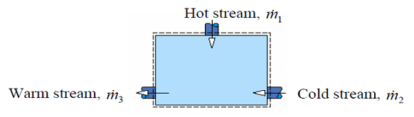
- This type of heat exchanger consists of a vessel where a hot stream and cold stream of the same fluid are mixed and exit at an intermediate temperature through a single outlet.
- Apply conservation of mass and First Law to the CV and assuming steady state, negligible KE and PE change to get:
- \cancel{\frac{dM_{cv}}{dt}} = \dot{m}_1 + \dot{m}_2 - \dot{m}_3
- 0 = \dot{m}_1 + \dot{m}_2 - \dot{m}_3
- \cancel{\frac{dE_{cv}}{dt}}=\cancel{\dot{Q}} - \cancel{\dot{W}} + \dot{m}_1(h_1)+\dot{m}_2(h_2) - \dot{m}_3(h_3)
- 0 = \dot{m}_1h_1 + \dot{m}_2h_2 - \dot{m}_3h_3
-
4.4.3 Boilers (Steam Generator)
- The function of a steam generator or a boiler is to convert water into steam at the desired temperature and pressure to suit the turbine which it serves. The basic components of steam generator (Figure 4-9) are furnace and fuel burning equipment, water walls, boiler surface (drum and tubes), superheater surface, air heater (pre-heater) surface, re-superheater surface, economizer surface (feed water heating), and several accessories.
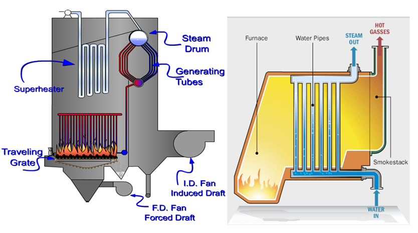
- Figure 4-9: Components of steam generator
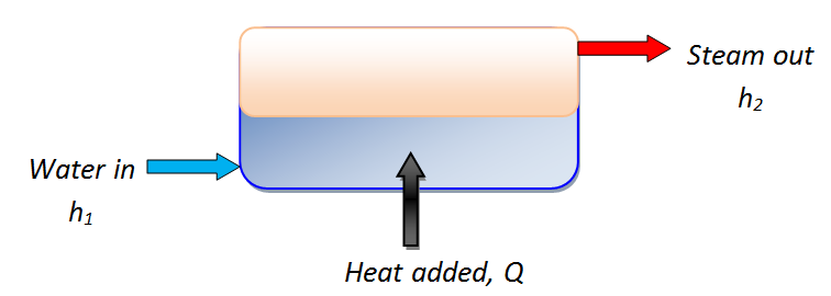
- Common assumptions for boilers:
- \Delta PE = \Delta KE = 0. \qquad \qquad \dot{W}=0
- The mass and energy balance become: \dot{m}_1=\dot{m}_2 =\dot{m}
- \dot{Q} - \dot{W} = \dot{m}[(h_2 - h_1) + g(z_2 - z_1) + \frac{1}{2}(c^2_2 - c^2_1)]
- \dot{Q} = \dot{m}(h_2-h_1)
Example:4-7
- In a gas fired boiler, water is boiled at 165°C by hot gases flowing through a stainless steel pipe submerged in water. Given that the rate of heat transfer from the hot gases to water is 74 kJ/s, determine the rate of evaporation of water.
- \dot{Q} = \dot{m}(h_2-h_1) \rightarrow \dot{m}= \frac{\dot{Q}}{(h_2-h_1)}
- \dot{Q} = 74kJ/s = 74kW
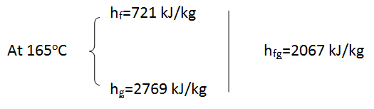
- \dot{m}=\frac{\dot{Q}}{(h_2 - h_1)}=\frac{74}{2067}=0.036 kg/s
-
4.5 Self-Assessment: Application of Steady Flow Energy Equation
- An industrial process discharges 5663.4 m3/min of gaseous combustion products at 205°C and atmospheric pressure. A proposed system for utilizing the combustion products combines a heat-recovery steam generator with a turbine, as shown in the figure below. At steady state, combustion products exit the steam generator at 127°C and atmospheric pressure and a separate stream of water enters at 275792.0 Pa, 39°C with a mass flow rate of 124.74 kg/min. At the exit of the turbine, the pressure is 6894.8 Pa and the quality of steam (dryness fraction) is 93%. Heat transfer from the outer surfaces of the steam generator and turbine can be ignored, as can the changes in kinetic and potential energies of the flowing streams. There is no significant pressure drop for the water flowing through the steam generator. The combustion products can be modelled as air and considered to behave as an ideal gas.
- a) Determine the power developed by the turbine, in kJ/min;
- b) Determine the turbine inlet temperature, in °C;
- c) Evaluating the power developed at £0.08/kW.hr which is a typical rate for electricity, determine the value of the power, in £/year, for 8000 hours of operation annually.
- Take atmospheric pressure as 101 kPa; molecular weight of air 28.97kg/kgmol

-
4.6 Week 4: Steady Flow Processes: Tutorials
- 1. Steam flows steadily through an adiabatic turbine. The inlet conditions of the steam are 10 MPa, 450°C, and 80 m/s. The exit conditions are 10 kPa, 92% quality (dryness fraction 0.92), and 50 m/s. The mass flow rate of the steam is 12 kg/s. Determine (a) the change in kinetic energy, (b) the power output, and (c) the turbine inlet area. (Ans: 195 kJ / kg; 10203.72kW; 0.004458m2 )
- 2. Argon gas enters an adiabatic turbine steadily at 900 kPa and 450°C with a velocity of 80 m/s and leaves at 150 kPa with a velocity of 150 m/s. The inlet area of the turbine is 60 cm2. Given that the power output of the turbine is 250 kW, determine the exit temperature of the argon. For argon take R = 0.2081 kJ/kg K and Cp = 0.5203 kJ/kg K. (Ans: 540.32K )
- 3. Air is compressed steadily by a 5kW compressor from 100kPa and 290 K to an outlet pressure at a rate of 1.6 kg/min. During this process the heat transfer between the compressor and the surrounding medium is negligible. Determine the maximum pressure that can be delivered by the compressor. Assume constant heat capacities for air (Cp =1.005kJ/kgK and Cv = 0.718kJ/kgK) (Ans: 568.9kPa )
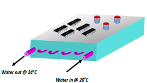
- 4. An electronic device is cooled at the top surface by convection to the surrounding at the rate of 0.8 kW and by water flowing through copper pipes inserted in the casing as shown in Figure Q6 below. The water enters the pipe at a velocity of 0.4 m/s and a temperature of 20°C and leaves at 24°C. The electrical component receives 0.5 kW of electrical power. Determine the diameter of the copper pipe. (Ans: 8.9mm )
- 5. Steam enters the condenser of a vapour power plant at 0.1 bar with a dryness fraction of 0.95 as shown in figure Q6. It is to be cooled by water from nearby river by circulating the water through the tubes within the condenser. The cooling water enters the tubes of the condenser at 20°C and leaves at 35°C with no change in pressure. Given that the steam leaves the condenser as saturated liquid at 0.1 bar and the changes in kinetic and potential energies of the flowing streams can be neglected, determine the ratio of the mass flow rate of the cooling water to the mass flow rate of condensing steam \left (\text{Ans:} \frac{m_c}{m_s}=36.24 \right )