06
-
- Vapour Power Cycles
- 6.1.1 Introduction
In any thermodynamic process, the use of working fluid gas or vapour is an essential working medium to convert heat into work. A cycle, which continuously converts heat into work, is called the power cycle. In a power cycle, the working fluid performs the various processes, which are suction, compression, expanding, condensing, etc. All these processes are performed repeatedly to generate the work or converting heat in to work. If the steam is alternatively vaporised and condensed, then the working cycle is called vapour power cycle.
There are various types of working fluids available such as steam, sodium, potassium and mercury. Some working fluids are used at high temperatures and some are at low temperatures. The steam is the mostly used working fluid in the vapour power cycles. The steam has the various desirable characteristics such as low cost, easy availability and high enthalpy of vaporization.
In this unit we will be discussing about the vapour power cycles, which are mostly used for steam power plants. The steam power plants are classified as coal plants, nuclear plants, natural gas or geothermal plants, depending on the type of fuel used to supply the heat to generate the steam.
To simplify the analysis, we shall assume that the change in kinetic and potential energies of the fluid between entry and exit are negligible compared with change in enthalpy. This implies that for the present purpose the energy equation can be written as
\varrho - W = \dot m(h_2 - h_1)
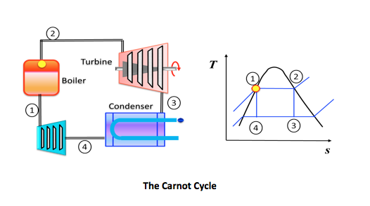
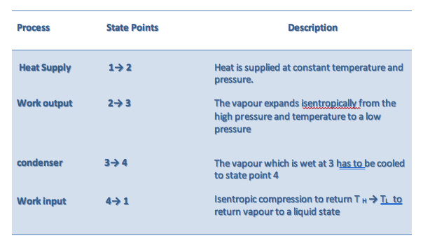
6.1.2 Carnot Cycle
• an ideal theoretical cycle that is the most efficient conceivable
• based on a fully reversible heat engine - it does not include any of the irreversibilities associated with friction, viscous flow, etc.
• in practice the thermal efficiency of real world heat engines are about half that of the ideal, Carnot cycle
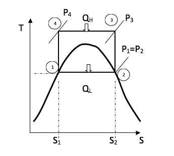
Cycle Efficiency:
Cycle efficiency is defined as the network output divided by the gross heat supplied
\eta = \frac{W_{net}}{\varrho _H}=\frac{\varrho _H - \varrho_L}{\varrho _H}= 1-\frac{T_L}{T_H}
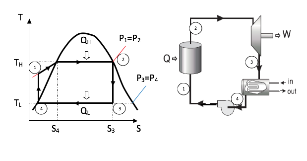
From the figure above the gross heat supplied is
\varrho_H-area(s_4 \rightarrow s_3\rightarrow2\rightarrow1\rightarrows_4)=T_H(s_3 - s_4)
\varrho_H - \varrho_l=area(4\rightarrow 3\rightarrow 2\rightarrow 1)=(T_H -T_L)(s_3 - s_4)
Therefore the Carnot efficiency is
\eta =\frac{(T_H - T_L)(s_3 - s_4)}{T_H(s_3 - s_4)}=1-\frac{T_L}{T_H}
Practical difficulties associated with the Carnot cycle
• at state point 4 the steam is wet at TL and it is difficult to pump water/steam (two phase) to state point 1
• the pump can be sized smaller if the fluid is 100% liquid water
• the pump is smaller, cheaper and more efficient
• can we devise a Carnot cycle to operate outside the wet vapour region
o between state points 4 and 3 the vapour must be isothermal and at different pressures -this is difficult to achieve
o the high temperature and pressure at 2 and 3 present metallurgical limitations
The net effect is that the Carnot cycle is not feasible for steam power plants. To resolve the difficulties associated with the Carnot cycle, the Rankine cycle was devised.
6.1.3 Rankine Cycle
There are two major reasons why the Carnot Cycle is not employed in practice:
● It has a low work ratio
● Because of practical difficulties associated with the compression. It would be difficult to control the condensation process so that it stopped at state 4 and then carry out the compression efficiently. The liquid tends to separate out from the vapour and the compressor would have to deal with a non-homogenous mixture. Moreover the volume of the fluid is high and the compressor would be comparable in size and cost with the turbine. It is comparatively easy on the other hand, to condense the vapour completely and compress the liquid to boiler pressure in a small feed pump. The resulting cycle, shown in figure below, is known as the Rankin cycle.
The simple Rankine cycle has the same component layout as the Carnot cycle shown above. The simple Rankine cycle continues the condensation process 3-4 until the saturated liquid line is reached.
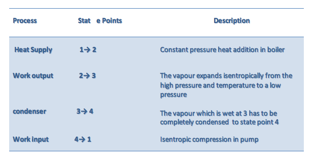
Determination of enthalpy at state 1 (h1)
The pump work is obtained from the conservation of mass and energy for steady-flow but neglecting potential and kinetic energy changes and assuming the pump is adiabatic and reversible.
\dot m_1 = \dot m_4 = \dot m
\dot m_1h_4 + \dot W_{pump} = \dot m_1h_1
\dot W_{pump} = \dot m(h_1 - h_4)
Since the pumping process involves an incompressible liquid, state 2 is in the compressed liquid region, we use a second method to find the pump work or the h across the pump.
Recall the property relation:
dh = T ds + v dP
Since the ideal pumping process 4-1 is isentropic, ds = 0. → dh = v dP
\Delta h = (h_1 - h_4) = \int_{1}^{4}vdp
v \cong v_4 = const.
(h_1 - h_4) \cong v_4(p_1 - p_4)
The pump work is calculated from
w_{pump} = \frac {\dot W_{pump}}{\dot m} = v_4(p_1 - p_4)
Example:
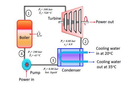
The figure below shows a simple vapour power plant operating at steady state with water circulating through the components. Relevant data at key locations are given on the figure. The mass flow rate of the water is 109 kg/s. Kinetic and potential energy effects are negligible as are all stray heat transfers.
Determine:
a. the thermal efficiency
b. the mass flow rate of the cooling water passing through the condenser, in kg/s.
Assumptions:
1) Control volumes enclosing each of the four components are at steady state.
2) For each control volume, kinetic/potential energy effects are negligible as are all stray heat transfers
Analysis:
For any power cycle, the thermal efficiency is the ratio of the net work developed to the heat added.
\eta = \frac {\dot W_{net}}{\dot \varrho_{in}} = \frac {\dot W_{turbine} - \dot W_{pump}}{\dot \varrho_{in}}
Applying energy rate balances to the turbine, pump and steam generator, respectively, yields;
\dotW_{turbine} = \dot m(h_1 - h_2)
\left | \dot W_{pump} \right | = \left |\dot m(h_3 - h_4) \right |
\dot \varrho_m = \dot m(h_1 - h_4)
State 3: exit of condenser
Since it stated that saturated liquid at 0.08 bar, thus h3 = hf @ 0.08 bar = 174 kJ/kg
State 4: entry to boiler
The pressure and temperature at state 4 are given as p4 = 100 bar and T4 = 43oC
Tsat @ 100 bar = 311oC which is > T4 thus the fluid is a compressed liquid at state 4 and h4 = hf @ 43oC = 180 kJ/kg
\eta =\frac{\dot m(h_1 - h_2) - |\dot m(h_3 - h_4)|}{\dot m(h_1 - h_4)}
= \frac{(3423.2-2335.8)-|(174-180)|}{(3423.2-180)}
= 0.3334
part (a) η = 33.34%
Applying mass rate balances to the condensor only, we get:
\dot m_2 = \dot m_3 = 109 kg/s and \dot m_5 = \dot m_6 = \dot m_{cw}
Using assumption (2) and applying energy rate balance to the condenser:
0 = \dot m_2(h_2 - h_3) + \dot m_{cw}(h_5 - h_6)
\dot m_{cw} = \frac{\dot m_2(h_2 - h_3)}{(h_6 - h_5)}
Since water is incompressible, we can approximate enthalpy as h=hf(T)
h5 = h5(20oC) = 83.96 kJ/kg
h6 = h6(35oC) = 146.08 kJ/kg
\dot m_{cw} = \frac{(109(2336.7-173.9))}{(146.08 - 83.96)}
Part (b) → \dot m_{cw} = 3759 kg/s
Example:
Determine the thermal efficiency of an ideal Rankine cycle for which steam leaves the boiler as superheated vapor at 6 MPa, 350oC, and is condensed at 10 kPa.
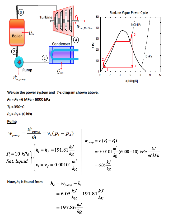
Boiler
To find the heat supplied in the boiler, we apply the steady-flow conservation of mass and energy to the boiler. If we neglect the potential and kinetic energies, and note that no work is done on the steam in the boiler, then
\dot m_2 = \dot m_3 = \dot m
\dot m_2h_2 + \dot \varrho_{in} = \dot m_3h_3
\dot \varrho_{in} = \dot m(h_3 - h_2)
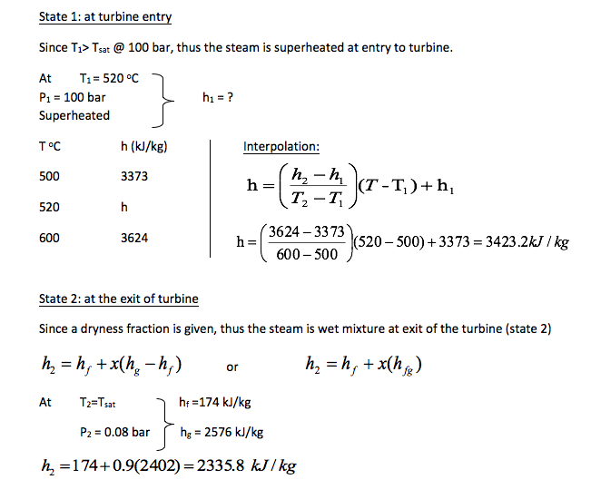
We find the properties at state 3 from the superheated tables as
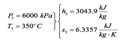
The heat transfer per unit mass is
q{in} = \frac {\varrho {_in}}{m} = h_3 - h_2
= (3043.9 - 197.86) \frac{kJ}{kg}
= 2845.1 \frac{kJ}{kg}
Turbine
The turbine work is obtained from the application of the conservation of mass and energy for steady flow. We assume the process is adiabatic and reversible and neglect changes in kinetic and potential energies
\dot m_3 = \dot m_4 = \dot m
\dot m_3h_3 = \dot W_{turb} + \dot m_4h_4
\dot W_{turb} + \dot m(h_3 - h_4)
We find the properties at state 4 from the steam tables by noting s4 = s3 = 6.3357 kJ/kg-K and asking three questions
at P_4 = 10kPa:s_j = 0.6492 \frac {kJ}{kg \cdot K}; s_g = 8.1488 \frac {kJ}{kg \cdot K}
is s 4 < s f ?
is s f < s 4 < s g ?
is s g < s 4 ?
s_4 = s_f + x_4s_{fg}
x_4 = \frac{s_4 - s_f}{s_{fg}} = \frac{6.3357 - 0.6492}{7.4996} = 0.758
h_4 = h_f + x_4h_fg
= 191.81\frac{kJ}{kg} + 0.758(2392.1)\frac{kJ}{kg}
= 2005.0\frac{kJ}{kg}
The turbine work per unit mass is
w_{turb} = h_2 - h_4
=(3043.9 - 2005.0)\frac{kJ}{kg}
= 1038.9\frac{kJ}{kg}
The net work done by the cycle is
w_{net} = w_{turb} - w_{pump}
= (1038.9 - 6.05)\frac{kJ}{kg}
= 1032.8\frac{kJ}{kg}
The thermal efficiency is
\eta_{th} = \frac{w_{net}}{q_{in}} = \frac{1032.8\frac{kJ}{kg}}{2845.1\frac{kJ}{kg}}
0.363 or 36.3%
6.1.4 Week 6a: The Vapour Power Cycles: Tutorials
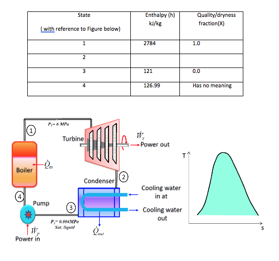
1. The steam power plant shown in Figure below operates on the ideal Rankine cycle between the pressure limits of 6.0 MPa and 0.004 MPa. Show the cycle on a T-s diagram with respect to saturation lines, and determine:
i. the missing values in Table below; [h2 = 1773 kJ/kg ; x2=0.679]
ii. the thermal efficiency of the cycle; [37.8%]
iii. the work ratio for the cycle; [0.9941]
iv. the Specific Steam Consumption (SSC). [3.582kg/kW h]
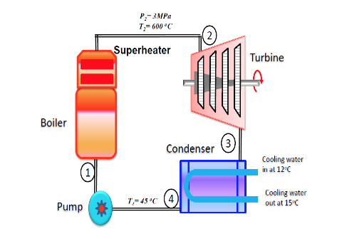
2. A small power plant produces 25 kg/s steam at 3 MPa, 600oC in the boiler. It cools the condenser with ocean water coming in at 12oC and returned at 15oC so the condenser exit is at 45oC. Determine the net power output and the required mass flow rate of ocean water. [32623kW; 4358.05 kg/s]
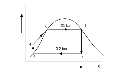
3. In a Rankine cycle, the steam of inlet to turbine is saturated at a pressure of 35 bar and the exhaust pressure is 0.2 bar. Determine :
a. The pump work, [3.54kJ/kg]
b. The turbine work, [7495.5kJ/kg]
c. The Rankine efficiency, [30.93%]
d. The condenser heat flow, and [16734.25kJ/kg]
e. The dryness at the end of the expansion. [0.747]
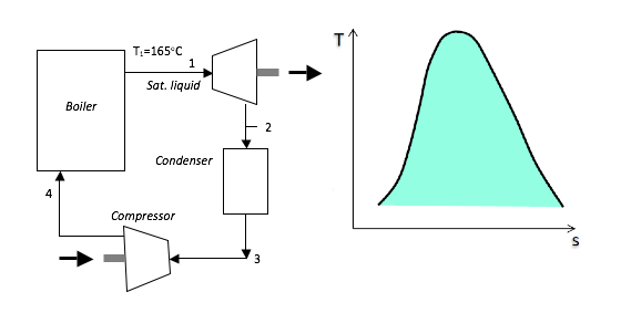
4. A Carnot cycle uses steam as the working fluid. The fluid is in the liquid state at the saturation temperature of 165oC at the beginning of the cycle and receives 1800 kJ/kg of heat during the isothermal expansion and hence the steam exits the boiler as a wet mixture. Given that the thermal efficiency is 21.20%.
a) Determine:
i) the condition of the steam at the end of the isentropic expansion; [2497kJ/kg;0.871]
ii) the net work transfer; [381.6kJ/kg]
iii) the cycle power output for a steam flow rate of 50kg/min. [422697.6W]
b) Show the cycle on a T-s diagram with respect to saturation lines.
-
- Gas Power Cycles
- Almost half of the world's electricity supply has been generated by producing steam utilizing fossil fuels such as coal, oil and gas and using this steam to drive a turbine/generator system to produce electricity. However, due to deregulation and privatisation of electricity generation industries throughout many of the 'new' generators have looked to the gas turbine as a source of electrical power since it offers many advantages over the traditional fossil fuel fired power plant, namely relatively low equipment cost and lead time, high fuel to energy efficiency and low emissions. As a result, such equipment has been and continues to be developed by the manufacturers to meet customer demand for larger, more efficient machines.
In its simplest sense, a gas turbine is a machine that is designed to convert the energy within a fuel into some form of usable power. It consists of three main parts; namely a compressor, a combustion chamber and a turbine.
6.2.1 Brayton (joule) Cycle
Working Principal:
Fresh air enters the compressor at ambient temperature where its pressure and temperature are increased. The high pressure air enters the combustion chamber where the fuel is burned at constant pressure. The high temperature (and pressure) gas enters the turbine where it expands to ambient pressure and produces work.
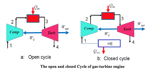
The cycle may operate on an open cycle when used as an automobile or truck engine, or on a closed cycle when used in a nuclear power plant. In open cycle operation the air exits the turbine as products of combustion to the atmosphere, as shown in Figure a below. In closed cycle operation an additional heat exchanger transfers heat from the cycle so that the air is returned to its initial state, as shown in Figure b below.
The main features of the cycle are:
⎯ Gas-turbine is used in aircraft propulsion and electric power generation.
⎯ High thermal efficiencies up to 44% can be achieved.
⎯ It can be combined with steam power cycle to form the combined power cycle providing greater efficiency
⎯ High power to weight ratio, high reliability, long life
⎯ Fast start up time, about 2 min, compared to 4 hr for steam-propulsion systems
⎯ High back work ratio (ratio of compressor work to the turbine work), up to 50%, compared to few percent in steam power plants.
6.2.2 Air-Standard Assumptions
In our study of gas power cycles, we assume that the working fluid is air, and the air undergoes a thermodynamic cycle even though the working fluid in the actual power system does not undergo a cycle.
To simplify the analysis we approximate the cycles with the following assumptions:
● The air continuously circulates in a closed loop and always behaves as an ideal gas.
● All the processes that make up the cycle are internally reversible.
● The combustion process replaced by a heat-addition process from an external source.
● A heat rejection process that restores the working fluid to its initial state replaces the exhaust process.
● The cold-air-standard assumptions apply when the working fluid is air and has constant specific heat evaluated at room temperature (25oC).
We assume the working fluid is air and the specific heats are constant and will consider the closed air standard cycle.
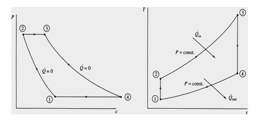
Process Description
1-2 Isentropic Compression (in a compressor).
2-3 Constant Pressure Heat Addition
3-4 Isentropic Expansion (in a turbine)
4-1 Constant Pressure Heat Rejection
The T-s and P-v diagrams are
We will be concerned with how the major parameters of the cycle affect the performance of heat engines. The performance is often measured in terms of the cycle efficiency.
\eta_{th} = \frac{w{net}}{\varrho_{in}}
We often use the Carnot efficiency as a means to think about ways to improve the cycle efficiency of other cycles.
\eta_{th,Carnot} = 1 - \frac{t_L}{T_H}
One of the observations about the efficiency of both ideal and actual cycles comes from the Carnot efficiency: Thermal efficiency increases with an increase in the average temperature at which heat is supplied to the system or with a decrease in the average temperature at which heat is rejected from the system.
Thermal Efficiency of the Brayton Cycle:
\eta_{th,Bryton} = \frac{W_{net}}{\varrho {in}} = 1 - \frac{\varrho _{out}}{\varrho _{in}} §
Now to find Qin and Qout.
Apply the conservation of energy to Process 2-3 for P = Constant (no work), steady-flow, and neglect changes in kinetic and potential energies.
\dot E_{in} = \dot E_{out}
\dot m_2h_2 + \dot \varrho_{in} = \dot m_3h_3
The conservation of mass gives
\dot m_{in} = \dot m_{out}
\dot m_2 = \dot m_3 = \dot m
For constant specific heats the heat added per unit mass flow is
\dot \varrho_{in} = \dot m(h_3 - h_2)
\dot \varrho_{in} = \dot mC_p(T_3 - T_2)
q_{in} = \frac{\dot \varrho_{in}}{\dot m} = C_p(T_3 - T_2)
The conservation of energy for the process 4-1 yields for constant specific heats (let’s take a minute for you to get the following result)
\dot \varrho_{out} = \dot m(h_4 - h_1)
\dot \varrho_{out} = \dot mC_p(T_4 - T_1)
q_{in} = \frac{\dot \varrho_{out}}{\dot m} = C_p(T_4 - T_1)
The thermal efficiency becomes
\eta_{th,Bryton} = 1 - \frac{\varrho_{out}}{\varrho_{in}} = 1 - \frac {q_{out}}{q_{in}}
= 1 - \frac {C_p(T_4 - T_1)}{C_p(T_3 - T_2)}
\eta_{th,Bryton}== 1 - \frac{(T_4 - T_1)}{(T_3 - T_2)}
\eta_{th,Bryton}== 1 - \frac{T_1(T_4/T_1 - 1)}{T_2(T_3/T_2 - 1)}
Recall processes 1-2 and 3-4 are isentropic, so
\frac {T_2}{T_1} = \left [ \frac {P_2}{P_1} \right ]^{(y-1)/y)} and \frac {T_3}{T_4} = \left [ \frac {P_3}{P_4} \right ]^{(y-1)/y)}
Since P3 = P2 and P4 = P1 we see that
\frac {T_2}{T_1} = \frac {T_3}{T_4} or \frac {T_4}{T_1} = \frac {T_3}{T_2}
The Brayton Cycle Efficiency becomes
\eta_{th, Bryton} = 1 - \frac {T_1}{T_2}
Is this the same as the Carnot Cycle efficiency?
Since process 1-2 is isentropic, using the isentropic relations
\frac {T_2}{T_1} = \left[ \frac{P_2}{P_1}\right ]^{(y-1)/y} = r_p^{(y-1)/y} \rightarrow \frac{T_1}{T_2} = \frac {1}{r_p^{y-1)/y}}
Where the pressure ratio is rp = P2/P1, hence, the thermal efficiency can be written as
\eta_{th, Bryton} = 1 - \frac {1}{r_p^{(y-1)/y}}
Of course, this expression for thermal efficiency was obtained using constant specific heats. For more accurate calculations the gas tables should be used.
In an actual gas turbine the compressor and the turbine are not isentropic; some losses do occur. These losses significantly reduce the efficiency of the gas turbine engine.
Another important feature of the gas turbine that seriously limits thermal efficiency is the high work requirement of the compressor, measured by the back work ratio Wcomp/Wturb. The compressor may require up to 80 percent of the turbine's output (a back work ratio of 0.8), leaving only 20 percent for net work output. This relatively high limit is experienced when the efficiencies of the compressor and turbine are too low. Solved problems illustrate this point.
Example:
The ideal air-standard Brayton cycle operates with air entering the compressor at 95 kPa, 22oC. The pressure ratio, rp, is 6:1 and the air leaves the heat addition process at 1100 K. Determine the compressor work and turbine work per unit mass flow, the cycle efficiency, the back work ratio, and compare the compressor exit temperature to the turbine exit temperature. Assume constant properties.
Apply the conservation of energy, steady-flow, neglect changes in kinetic and potential energies to Process 1-2 for the compressor. Note that the compressor is isentropic.
\dot E_{in} = \Dot E_{out}
\dot m_1h_1 + \dot W_{comp} = \Dot m_2h_2
The conservation of mass gives
\dot m_{in} = \dot m_{out} \rightarrow \dot m_1 = \dot m_2 = \dot m
For constant specific heats the compressor work per unit mass flow is
\dot W_{comp} = \dot m(h_2 - h_1)
\dot W_{comp} = \dot mC_p(T_2 - T_1)
w_{comp} = \frac{\dot W_{comp}}{\dot m} = C_p(T_2 - T_1)
Since the compressor is isentropic
\frac{T_2}{T_1}=\left [ \frac{P+2}{P_1} \right ]^{(y-1)/y} = r_p^{(y-1/y)}
T_2 = T_1r_p^{(y-1)/y}
w_{comp} = C_p(T_2 - T_1)
= 1.005(492.5 - 295) = 198.15kJ/kg
The conservation of energy for the turbine, process 3-4, yields for constant specific heats (let’s take a minute for you to get the following result)
\dot W_{turb} = \dot m(h_3 -h_4)
\dot W_{turb} = \dot mC_p(T_3 - T_4)
w_{turb} = \frac{\dot W_{turb}}{\dot m} = C_p(T_3 - T_4)
Since process 3-4 is isentropic
\frac {T_4}{T_3} = \left [ \frac {P_4}{P_3}\right ]^{(y-1)/y}
Since P3 = P2 and P4 = P1 we see that
\frac{T_4}{T_3}=\left [ \frac{1}{r_p} \right ]^{(y-1)/y} \rightarrow T_4 = T_3\left [ \frac{1}{r_p} \right ]^{(y-1)/y}= 1100\left ( \frac{1}{6} \right )^{0.4/1.4} = 659.1K
w_{turb} = C_p(T_3 - T_4)
w_{turb} = 1.005(1100 - 659.1)
w_{turb} = 442.5kJ/kg
We have already shown the heat supplied to the cycle per unit mass flow in process 2-3 is
q_{in} = C_p(T_3 -T_2)
q_{in} = 1.005(1100 -429.5) = 609.6kJ/kg
The net work done by the cycle is
w_{net} = w+{turb} - w_{comp} = 442.5 - 198.15 = 244.3kJ/kg
The cycle efficiency becomes
\eta_{th,Brayton} = \frac{w_{net}}{q_{in}} = \frac{244.3}{\varrho_{in}609.6} = 0.4 (40\%)
The back work ratio is defined as
BWR = \frac{w_{in}}{w_{out}}=\frac{w_{comp}}{w_{turb}}=\frac{198.15}{442.5}= 0.448
Note that T4 = 659.1K > T2 = 492.5K, or the turbine outlet temperature is greater than the compressor exit temperature. Can this result be used to improve the cycle efficiency?
What happens to ηth, win /wout, and wnet as the pressure ratio, rp is increased?
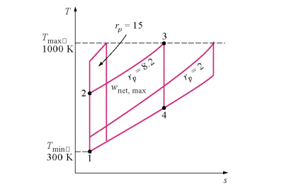
Let's take a closer look at the affect of pressure ratio on the net work done.
w_{net} = w_{turb} - w_{comp}
= C_p(T_3 - T_4) - C_p(T_2 - T_1)
\eta_{th,Bryton} == C_pT_3(1 - T_4/T_3) - C_pT_1(T_2 /T_1 - 1)
w_{net} = c_pT_3(1-\frac{1}{r_p^{(k-1)/k}}) - C_pT_1(r_p^{(k-1)/k}-1)
Note that the net work is ZERO when
r_p = 1 \quad and \quad r_p= \left [ \frac{T_3}{T_1} \right ]^{(y-1)/y}
For fixed T3 and T1, the pressure ratio that makes the work a maximum is obtained from:
This is easier to do if we let
r_p^{(k-1)/k}
w_{net} = C_pT_3(1-\frac{1}{X})-C_pT_1(X-1)
\frac{dw_{net}}{dr_p}=C_pT_3(0-(-1)X^{-2})-C_pT_1(1-0 )=0
Solving for X
X^2=\frac{T_3}{T_1}=r_p^{2(y-1)/y}
-
- Week 6: Gas Power Cycles Tutorials
Note: for this set of tutorials please take for air Cv = 0.718 kJ/kgK, Cp = 1.005 kJ/kgK and ɤ = 1.4
1. A large stationary Brayton cycle gas-turbine power plant delivers a power output of 100 MW to an electric generator. The minimum temperature in the cycle is 300 K, and the maximum temperature is 1600 K. The minimum pressure in the cycle is 100 kPa, and the compressor pressure ratio is 14 to 1. Calculate the power output of the turbine. What fraction of the turbine output is required to drive the compressor? What is the thermal efficiency of the cycle? (Ans: 166.32MW; 0.399; 53%)
2. A simple ideal Brayton cycle using air as the working fluid between the pressure limits of 100 and 2000K. The air enters the compressor at 300K and exit the turbine at 1000K. Determine the network output, and the thermal. The properties of air at room temperature are Cp = 1.005 kJ/kg·K and k = 1.4 (Ans: 169.9 kJ/k; 57.5% )
3. An aircraft engine operates on the simple ideal Brayton cycle with air as the working fluid has a pressure ratio of 10. The air enters the compressor at 273K and receives 500kW before it enters the turbine. Determine the net power and the thermal efficiency assuming constant specific heats at room temperature. (Ans: 241.2kW; 48.2%)
4. Air enters the compressor of a gas-turbine engine at 300 k and 100 kPa, where it is compressed to 700 kPa and 580 K. A 950 kJ/kg of heat is transferred to air before it enters the turbine. For a turbine efficiency of 86% determine (a) the fraction of the turbine work output used to drive the compressor and (b) the thermal efficiency. Assume assuming constant specific heats at room temperature. (Ans: 51.1% ; 29.6% ) -
- right