01
-
- Preview (Basic Concepts of Thermodynamics)
- Introduction: This module examines various energy resources ranging from conventional sources, i.e. fossil fuels, to renewable energy resources such as wind, solar, tidal, wave, etc. and their conversion and utilisation. An understanding of different types of energy resources, their use, effectiveness and limitations will be developed. Environmental impacts of energy production and use will be assessed. Techniques will be developed to assess the available resources and optimal solutions through application of knowledge and understanding of fundamental scientific principles.
Many engineering systems involve the generation, transfer and conversion of energy and the branch of engineering sciences that deal with it is referred to as thermodynamics. A power plant is a prime example that can be defined as a machine or assembly of equipment that generates and delivers a flow of mechanical or electrical energy. The main equipment for the generation of electric power is generator. When coupling it to a prime mover runs the generator, the electricity is generated.
In the first part of this module a thermodynamic revision section is presented dealing with the characteristics of some the common substances such as water and air, which give us the energy content in the substance, and enable us to analyse the performance of various thermodynamic systems, including a range of heat engines such as turbines (steam or gas types) and compressors.
However, we will not be involved in the design of engines components such as the shape of turbine blades, the piston and cylinder of an internal combustion engine, as each of these is a special subject in its own right. Instead these components are lumped inside a “black box” and our analysis considers the energy and work (or power) that flows in and out of the “box”.
Take the example of analysing the performance of a power station: After studying this subject you are able to walk into a power station; and, by asking the operators/engineers about the operation environment of the power generation system, you will be able to give a good estimate of the energy output of the power station and its efficiency.
On the other hand, in the design stage for a power station, what you will learn from this subject will enable you to work out the specifications of the boiler and turbine(s) that are required to deliver a given power.
All these analyses are based on the conservation of energy which will be known as the “First Law of Thermodynamics”.
Then there is the “Second Law of Thermodynamics”. Some of you most likely this is their first encounter with this Law. The consequence of this law covers a wide range of our everyday life: from the rationale for why a cup of hot coffee will turn cold to cosmology. This Law will explain why you need a radiator in your car to lose heat into the atmosphere in order for the car to work (even necessary for an ideal car engine that never overheats). However the interesting part of applying this law is that you will be able to work out the maximum efficiency (certainly nowhere near to 100%) of a thermodynamic system. When presented with a machine that came with a claim of certain operation efficiency, without having to open up the machine to examine the working mechanism, by applying the Second Law you will be able to determine whether the claim is feasible or not. -
- Thermal Sciences
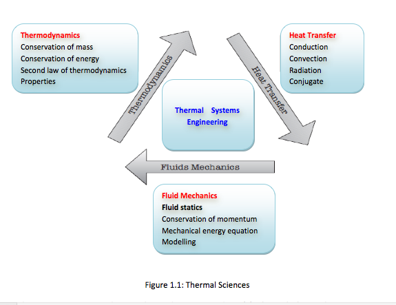
- The thermal sciences involve the storage, transfer and conversion of energy. We will study the basic laws and principles that govern the three disciplines of thermal sciences, namely, thermodynamics, heat transfer and fluid mechanics (Figure 1.1)
There are two approaches in thermodynamics studies: (1) classical thermodynamics – a macroscopic approach where the whole system is viewed as one entity. It does not require knowledge of behaviour of individual particles. It is the direct and easy method of solving engineering problems, (2) statistical thermodynamics – is a microscopic approach based on average behaviour of large groups of individual particles. It is rather involved. In this course, the classical approach is adopted. -
- Thermodynamic Systems
Systems and Control Volumes
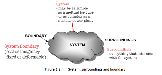
System = a quantity of matter or a region in space chosen for study
Surroundings = the mass or region outside a system
Boundary = real or imaginary surface that separates the system from its surroundings. The boundary can be fixed or movable. It is a contact surface shared by both the system and its surroundings. Mathematically it has zero thickness, contains no mass and zero volume.
Closed System = (or control mass) consists of a fixed amount of mass, and no mass can cross its boundary. No mass can enter or leave a closed system, but energy (heat and work) can cross the boundary.
Open System = (or control volume) is a properly selected region is space, for which both mass and energy can cross the boundary.
Control Surface = boundaries of a control volume. -
- Thermodynamic Properties of Systems
- 1.3.1 Basic Definitions
Thermodynamic Property: Any observable or measurable characteristic of a system. Any mathematical combination of the measurable characteristics of a system
Property = any characteristic of a system. For example: pressure P, temperature T, volume V, and mass m.
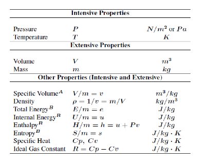
Intensive property = property that is independent of the mass of a system, such as P, T.
Extensive property = property that depends on the size – or extent – of the system, such as mass, volume.
Generally, uppercase letters denote extensive properties (m is an exception). Lowercase letters are used for intensive properties (P and T are exceptions). Specific property = extensive properties per unit mass. For example: specific volume (v = V/m) and specific internal energy (u = U/m).
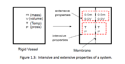
To differentiate between intensive and extensive properties, divide the system into 2 equal parts (Figure 1.3). Each part will have the same value of intensive properties as the original system, but half the value of the extensive properties, as shown below.
1.3.2 Density and Relative Density
Density = mass per unit volume,
p = \frac{m}{V}, (kg/m3)
Specific volume = volume per unit mass (i.e. reciprocal of density),
v = \frac{v}{m} = \frac{l}{p} (m3/kg)
Specific gravity (or relative density) = ratio of density of a substance to the density of some standard substance at a specified temperature (usually water at 4oC; = 1000 kg/m3).
Relative Density
RD = \frac{P}{P H2O}
Specific weight = the weight of a unit volume of a substance. w=pg (N/m3)
where g is the gravitational acceleration. -
- State and Equilibrium
- At a given state, all the properties of a system have fixed values.
In an equilibrium state there are no unbalanced potentials (or driving forces) within the system.
For thermodynamic equilibrium, the following conditions must be satisfied:
1. Thermal equilibrium – the temperature is the same throughout the entire system
2. Mechanical equilibrium – there is no change in pressure at any point of the system with time.
3. Phase equilibrium – the mass of each phase reaches an equilibrium level and stays there.
4. Chemical equilibrium – the chemical composition is does not change with time – that is, no chemical reactions occur
The State Postulate
The state postulate specifies the number of properties required to fix a state of a system: “The state of a simple compressible system is completely specified by two independent, intensive properties”.
A simple compressible system implies the absence of electrical, magnetic, gravitational, motion, and surface tension effects. The effects are due to external force fields and are negligible for most engineering problems. For each effect that is significant, an additional property needs to be specified – for example, if gravitational effects are important the elevation z needs to be specified in addition to the two properties required.
Two properties are independent if one property can be varied while the other one is held constant. Temperature and specific volume are always independent properties. Temperature and pressure are dependent properties for multiphase systems. -
- Processes and Cycles
- Process = any change that a system undergoes from one equilibrium state to another.
Path = series of states through which a system passes through during a process.
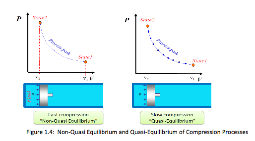
Quasi-static (or quasi-equilibrium) process = a process that proceeds in such a way that the system remains infinitesimally close to an equilibrium state at all times. It is a sufficiently slow process that allows the system to adjust itself internally so that properties in one part of the system do not change any faster than those at other parts.
It is an idealized process and not a true picture of the real process, but many actual processes can be approximated as one – with negligible error.
Implication of a quasi-static process: (1) easy to analyze, (2) work-producing devices (e.g. heat engine) deliver the most work when they operate on such processes. A process can be shown on a process diagram, where the coordinates are properties between the initial and final states,
• For nonquasi-equilibrium process, the path is denoted by a dashed line
• For quasi-equilibrium process, the path on process diagram is shown as a solid line
The prefix iso- denotes a process for which one property remains constant.
• Isothermal process – constant temperature process
• Isobaric process – constant pressure process
• Isochoric process – constant specific volume
Cycle or Cyclic Process: A system is said to have undergone a cycle if it returns to its initial state at the end of the process (Figure 1.5). A steam power cycle is an example of a process in which a fluid is alternatively vaporized and condensed.
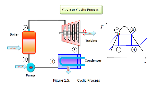
Cycle = a series of processes where the system returns to its initial state at the end of the process.
i.e. initial state = final state. -
- Temperature and the Zeroth Law of Thermodynamics
- The zeroth law states that “If two bodies are in thermal equilibrium with a third body, they are also in thermal equilibrium with each other” – serves as basis for temperature measurement.
By replacing the third body with a thermometer, the law can be restated as “two bodies are in thermal equilibrium if both have the same temperature reading even if they are not in contact”.
It was first formulated and labeled by R H Fowler in 1931. It is named the zeroth law, because this most basic principle was only recognized after the formulation of the 1st and 2nd laws.
1.6.1. Temperature Scales The commonly used temperature scales are the two-point scales – Celsius scale (SI unit) or Fahrenheit scale (English unit). These are based on two points – the freezing and boiling points of water.
Thermodynamic temperature scale = temperature scale that is independent of the properties of any substance or substances.
• In SI system it is known as the Kelvin scale. Unit is Kelvin (K)
• In English system it is the Rankine scale. Unit is Rankine (R)
Temperature relations:
At standard pressure (1.01325 bar = 101.325 kPa = 1 atmosphere):
• Freezing point of water = 0oC = 32 oF
• Boiling point of water = 100oC = 212oF
It can be easily shown that: T (oF) = 1.8 T (oC) + 32
To convert from the Celsius scale to the Kelvin scale, a simple mapping is made, T (K) = T (oC) + 273.15
Similarly, a simple mapping between the Fahrenheit scale and the Rankine scale gives, T (R) = T (oF) + 459.67
It can also be shown that, T (R) = 1.8 T (K) NOTE: At absolute zero, both absolute temperature and absolute pressure are zero regardless of the type of scales used! -
- Pressure
- Pressure = normal force exerted by a fluid per unit area.
Pressure is exclusive to gas or liquid. In solids its counterpart is normal stress. It has the units: N/m2 called a Pascal (Pa) where,
1 Pa = 1 N/m2
Other units are often used,
1 bar = 105 Pa = 0.1 MPa = 100 kPa
1 atm = 101325 Pa = 101.325 kPa = 1.10325 bars = 14.696 psi
Actual pressure = absolute pressure, measured relative to absolute vacuum (i.e. absolute zero pressure)
Most pressure-measuring devices indicate pressure difference relative to the atmospheric pressure. When the absolute pressure of the system is above atmospheric pressure, the difference is known as gauge pressure, as measured by a pressure gage
Pgauge = Pabs – Patm
Vacuum gages indicate the difference between the atmospheric pressure and the absolute pressure (of a system). When the absolute pressure is lower than the atmospheric pressure, the difference is known as vacuum pressure,
Pvac = Patm – Pabs
Note: In thermodynamic relations and tables, pressures used are almost always absolute. We will adopt a convention where P denotes absolute pressure.
Often the letters “a” and “g” are added to pressure units, such as psia and psig. “a” is absolute while “g” is gauge pressure,
• Pressure at any point in a fluid is the same in all directions. That is, it has magnitude but not a specific direction, and thus it is a scalar quantity not a vector quantity.
1.7.1 Manometers
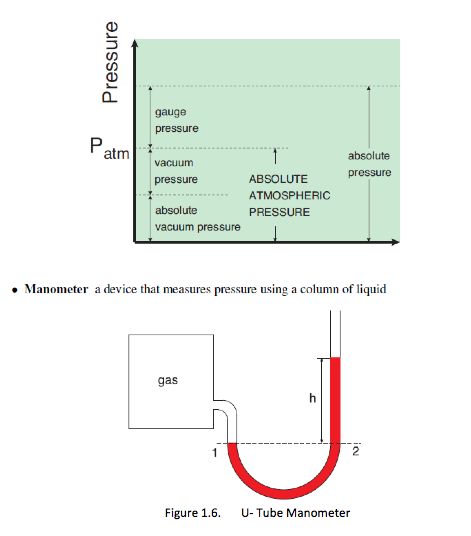
– the fluid pressure at point 1 in a manometer is given as P1 - Patm + pgh
Bourdon Tube - a device that measures pressure using mechanical deformation
Pressure Transducer - devices that use piezoelectrics to measure pressure
Barometer - device tha measures atmospheric pressure.
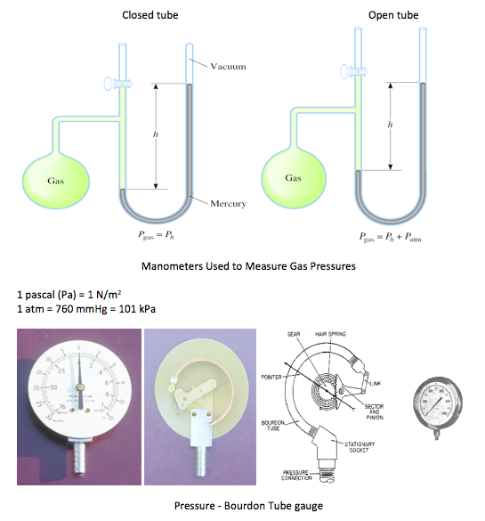
• A Bourdon gauge uses a coiled tube which as it expands due to pressure increase causes a rotation of an arm connected to the tube
• The pressure sensing element is a closed coiled tube connected to the chamber or pipe in which pressure is to be sensed
• As the gauge pressure increases the tube will tend to uncoil, while a reduced gauge pressure will cause the tube to coil more tightly
• This motion is transferred through a linkage to a gear train connected to an indicating needle. The needle is presented in front of a card face inscribed with the pressure indications associated with particular needle deflections
• In a barometer, the Bourdon tube is sealed at both ends and the absolute pressure of the ambient atmosphere is sensed
• Differential Bourdon gauges use two Bourdon tubes and a mechanical linkage that compares the readings
• Note that a Bourdon gauge can measure liquid pressure as well as gas pressure -
- Relationship between Work Energy and Heat
- Work was defined previously as the force times the distance moved in the direction of that force. When dealing with a thermodynamic system however it is more likely to encounter pressure than force, and volume change rather than displacement. By analysing a simple closed system a relationship between work pressure and volume can be developed. A cylinder piston assembly is shown in Figure 1.7 (a). The working fluid exerts a pressure on the piston that results in a force that causes the piston to move. The work done is then the force times the distance moved. Assuming that the pressure remains constant,
Work = Force x (L2 - L1)
As stated previously, however, it is better to work using pressure and volumes. Considering the working fluid contained in the system boundary (Figure 13 (b)), the volume of fluid contained in this closed system is the cross-sectional-area times the length L1. After expansion the volume equals the area times the new length L2. Therefore for both volumes,
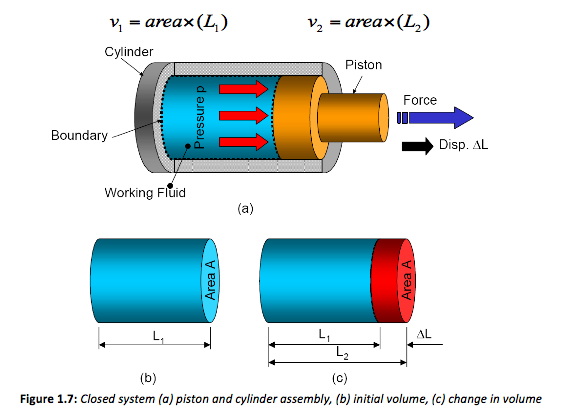
Both these equations can be re-arranged to make L the subject, thus changing Equation 1 to,
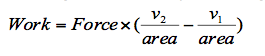
Since pressure is equal to force divided by area then,
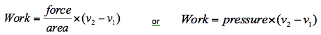
This final solution can be generalised further by plotting the process on a pressure-volume chart, or p-v diagram as shown in Figure 1.8. These types of plots are used widely in thermodynamics to illustrate processes.
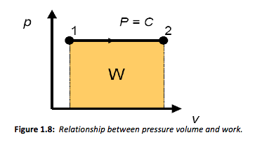
From Equation 4 it is apparent that work is given by the pressure times the change in volume. It is interesting to note that the area under the line described by the same constant pressure expansion shown in Figure 1.8 is also equal to the pressure times the change in volume or work. Then more generally we can describe the area under the curve as,
W = ∫ pdv
This derivation is a simplified version of the actual process, but nevertheless illustrates the principles involved. Now that work is described as a function or pressure and volume it is possible to combine work being done by the system (positive values) and work done on the system (negative values). -
- None-Flow Energy Equation (first law of thermodynamics)
- The heat energy supplied to or extracted from a system is equal to the change in internal energy plus the work done. Or said another way, the change in internal energy is equal to the heat supplied minus the work done. Then mathematically,
Q - W = ΔU
This equation is known as the non-flow energy equation and is shown here in the actual value form. Capital letters indicate an energy value for a known mass of the working fluid. The specific form of the equation would be given as,
q - w = Δu
The units of each variable are J/kg. A mixture of specific and non specific can also be achieved thus,
Q - W = m(u2 - u1)
Where m is the mass of the working fluid. Here the units are simply Joules.
When a system undergoes a thermodynamic cycle the net heat supplied to the system from its surroundings minus the net work input to the system from its surroundings must equal zero.
This statement can also be written in mathematical terms as,
∑q - ∑w = 0
The cycle summation is represented by ∑. This symbol means that all the work or heat values are added together for the complete cycle.
-
- Tutorial (Revision)
 1. The basic barometer can be used to measure the height of a building. If the barometric readings at the top and at the bottom of a building are 730 and 755 mm Hg, respectively, determine the height of the building. Take the densities of air and mercury to be 1.18 kg/m3 and 13,600 kg/m3, respectively.
(Ans: h = 288.6 m)
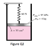 2. A gas is contained in a vertical, frictionless piston–cylinder device. The piston has a mass of 4 kg and a cross-sectional area of 35 cm2. A compressed spring above the piston exerts a force of 60 N on the piston. If the atmospheric pressure is 95 kPa, determine the pressure inside the cylinder.
(123.4kPa)
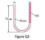 3. Consider a U-tube whose arms are open to the atmosphere. Now water is poured into the U-tube from one arm, and light oil (ρ = 790kg/m3) from the other. One arm contains 70cm high water, while the other arm contains both fluids with an oil-to-water height ratio of 4. Determine the height of each fluid in that arm.
(Ans: hw= 0.168m; ho = 0.673m)
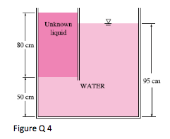 4. The top part of a water tank is divided into two compartments, as shown in Fig. 4. Now a fluid with an unknown density is poured into one side, and the water level rises to a certain amount on the other side to compensate for this effect. Based on the final fluid heights shown on Figure 4, determine the density of the fluid added. Assume the liquid does not mix with water.
(Ans: ρf =562.5kg/m3)
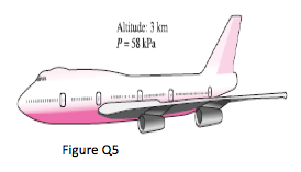 5. The pilot of an airplane reads the altitude 3000 m and the absolute pressure 58 kPa when flying over a city. Calculate the local atmospheric pressure in that city in kPa and in mm Hg. Take the densities of air and mercury to be 1.15 kg/m3 and 13,600 kg/m3, respectively.
(Ans: 98.1kPa; 688mmHg)
6. Unit mass of a fluid at a pressure of 3 bar, and with a specific volume of 0.18 m3/kg, contained in a cylinder fitted with a piston expands reversibly to a pressure of 0.6 bar according to the law p = c/v2, where c is a constant. Calculate the work done during the process.
7. A unit mass of a certain fluid is contained in a cylinder at an initial pressure of 20 bar. The fluid is allowed to expand reversibly behind a piston according to a law pV2 = C until the volume is doubled. The fluid is then cooled reversibly until the piston regains its original position; heat is supplied reversibly with the piston firmly locked in position until the pressure rises to the original value of 20 bar. Calculate the net work done by the fluid for an initial volume of 0.05 m3.
8. In a certain steam plant the turbine develops 1000 kW. The heat supplied to the steam in the boiler is 2800 kJ/kg, the heat rejected by the steam to the cooling water in the condenser is 2100 kJ/kg and the feed-pump work required to pump the condensate back into the boiler is 5 kW. Calculate the steam flow rate.
9. In the compression stroke of an internal combustion engine the heat rejected to the cooling water is 45kJ/kg and the work input is 90kJ/kg. Calculate the change in specific internal energy of the working fluid, stating whether it is gain or loss.
10. In the cylinder of an air motor the compressed air has a specific internal energy of 420 J/kg at the beginning of the expansion and a specific internal energy of 200 kJ/kg after expansion. Calculate the heat flow to or from the cylinder when the work done by the air during the expansion is 100 kJ/kg.