01
-
1.0 Introduction
- This module provides a detailed coverage of object-oriented analysis and design of software systems. It provides coverage of the Unified Modelling Language (UML) notation and the practical application of UML in the development of information systems using currently available software modelling tools. It will also provide coverage of the use of Analysis and Design Models
Learning Outcomes
- On completion of this module, students should be able to:
- Understand and apply object oriented techniques to the analysis and design of software systems
- Develop object oriented specifications using the Unified Modelling Language (UML)
- Develop UML models using currently available software modelling tools
- Understand the integration between the design models and implementation
Syllabus Overview
Object Oriented Analysis And Design.
- An overview of the conceptual foundations of Object Oriented Analysis and Design.
Class Diagrams
- Objects, classes, attributes, operations, inheritance, aggregation, association, and generalisation.
- The development of class diagrams.
- The role of 'class diagrams' in analysis and design models.
Component Diagrams
- Components, component interfaces
- Modelling system components using component diagrams.
Interaction Diagrams
- Modelling object interaction using interaction diagrams (sequence diagrams, communication diagrams, interaction overview diagrams and timing diagrams).
Activity Diagrams
- Activities, actions, edges, decision nodes, merge nodes, partitions, fork nodes, join nodes, objects in activities
- The development of Activity Diagrams during business analysis to model workflow and business processes
Dynamic Modelling
- States, transitions, actions and events
Traceability
- from Requirements through to Implementation
Useful books
- Schaum’s Outlines – UML; Bennett, Skelton & Lunn, McGraw-Hill (2005) second edition ISBN 0-07-710741-1
- Bennet, Skelton & Lunn (2005), Schaum's Outlines - UML, 2nd Ed, McGraw-Hill [ISBN 0-07-710741-1]
- Perdita Stevens (2006), Using UML: Software Engineering With Objects And Components, 2nd Ed, Addison Wesley [ISBN 0-321-26967-5]
- Martin Fowler (2006), UML Distilled: A Brief Guide To The Standard Object Modelling Language, 3rd Ed, Addison Wesley [ISBN 0-321-19368-7]
- Dennis, Wixom and Tegarden (2005), Systems Analysis And Design With UML Version 2.0 An Object-Oriented Approach, 2nd Ed, Addison Wesley [ISBN 90-471-65920-7]
-
1.1 What is the Software Process?
- The software process is the cornerstone of successful software engineering. It is the Life Cycle that the software goes through from conception to retirement. The process can be thought of as a set of activities that covers the complete life span of a piece of software. Activities commence when the software is envisaged, and give structure to its development stage. However, they also continuing through its operational lifetime until the product is finally ‘retired’. Life cycle models links these activities.
- You should be familiar with the main life cycle models from the Fundamentals of Software Engineering course. We will use some of these slides during this lecture
- Some Life Cycle Models include the following …..
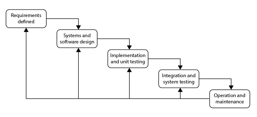
- The Waterfall Model
- The “traditional” approach to software development is to use the waterfall model. The expectation is to complete each step before proceeding to the next step in the process.
- The steps in this model are as follows:
- Incremental Approach
- There are alternatives to the Waterfall model. These alternatives come under the name “Agile”. Agile approaches utilise a different “ordering” of the development steps.
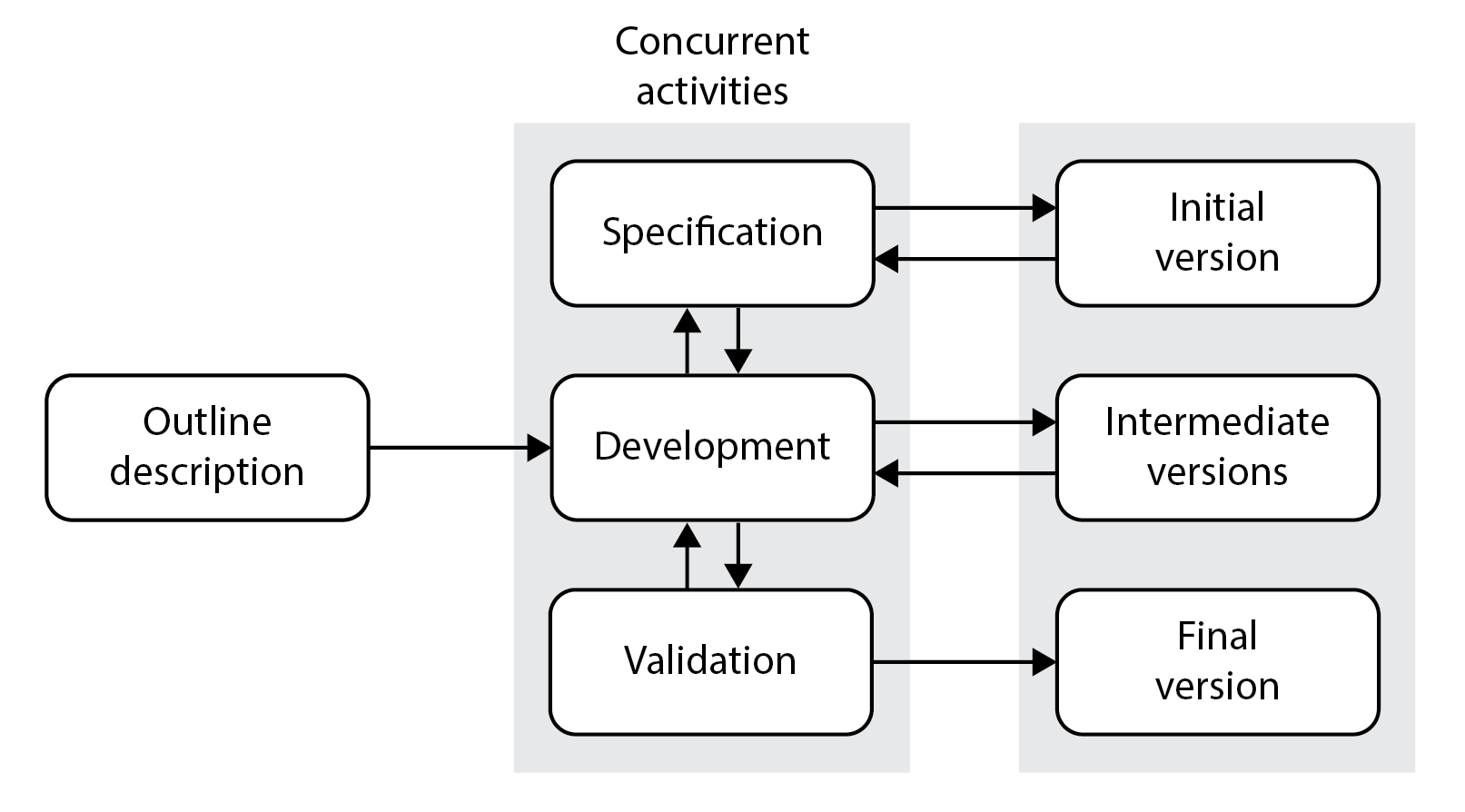
- Agile Development
- The fundamental characteristics of agile development are:
- Specification, Design and implementation are interleaved
- The system being built is developed in a series of versions
- An interactive approach is used to develop the User Interface
- The key then is to develop the system in increments
- Ideally increments should be made available to customers every 2 or 3 weeks involving customers in the development process.
-
1.2 Main life cycle activities
- Even, though these life cycle models were different - they still included the following core activities that are at the heart of the software process:
- Analysis
- Design
- Coding
- Testing
- Maintenance
Systems analysis :
- Understand what the system must do.
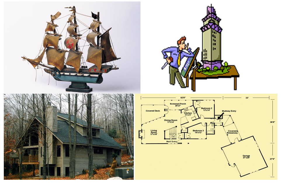
Systems design:
- Specify how the components are configured to provide the solution.
Systems Analysis
- Systems Analysis consists of those activities that enable a person to UNDERSTAND and SPECIFY what the new system should accomplish. Systems Analysis is much more than simply a brief statement of the problem, it describes in detail the “what” that a system must do to satisfy the need or to solve the problem.
Systems Design
- Systems Design consists of those activities that enable a person to describe in detail the system that SOLVES the need. In other words, systems design describes “how” the system will work and it specifies in detail all the components of the solution
- Scenarios
Scenario 1.
- urrent System is a ‘manual’ Paper-based System (e.g. Library using files/forms) which requires a new ‘computerised’ software system.
Scenario 2.
- Customer would like a new software system as there is no existing system.
Scenario 3.
- Customer would like a new software system based on an existing system.
- In ALL scenarios – MUST do Analysis
-
1.3 Analysis
- Systems Analysis activities:
- Gather detailed information
- Define requirements
- Prioritize requirements
- Develop user-interface dialogues
- Evaluate requirements with users
1. Gather Detailed Information
- Systems analysts obtain information from people who will be using the system, either by interviewing them or by watching them work. Analysts also study existing systems, including their documentation. They try to understand an existing system by identifying and understanding the activities of all users
- Information-Gathering Techniques
- Interviewing users and other stakeholders
- Distributing and collecting questionnaires
- Reviewing inputs, outputs, and documentation
- Observing and documenting business procedures
- Researching vendor solutions
- Collecting active user comments and suggestions
2. Define Requirements
- The analyst uses information gathered from users and documents to define requirements for the new system.
- functional requirements
- the activities that the system must perform (i.e., the business uses to which the system will be applied).
- non- functional requirements
- related issues such as user interface formats and requirements for reliability, performance, and security
- Functional Requirements :
- Functions Business rules and processes
- Non-functional Requirements :
Usability               User interface, ease of use
Reliability             Failure rate, recovery methods
Performance        Response time, throughput
Security                Access controls, encryption
Implementation     Development tools, protocols
Physical                Size, weight, power consumption.
                             Installation and updates
3. Prioritize Requirements
- Once the system requirements are well understood, it is important to establish which requirements are most crucial for the system. Sometimes, users suggest additional system functions that are desirable but not essential. However, users and analysts need to ask themselves which functions are truly important and which are fairly important but not absolutely required.
4. Develop User-Interface Dialogues
- To most users, the user interface is all that matters. Thus, developing user-interface dialogs is a powerful method of eliciting and documenting requirements A user-interface prototype developed in an early iteration can be expanded in later iterations to become a fully functioning part of the system.
5. Evaluate Requirements with Users
- Analysts usually use an iterative process in which they :
- obtain user input
- work alone to model requirements
- return to the user for additional input or validation,
- work alone to incorporate the new input and refine the models.
- Prototypes of user interfaces and other parts of the system may also be developed
-
1.4 Why Build Models?
- System Modelling
- This is the process of developing abstract models of the system that is being developed. This approach will involve some form of diagram …. UML Diagram. Models are used at different points in the development process.
- Models and Modelling
- UML@Classroom Chapter 1
- Natural Language is not a good choice as it is imprecise and ambiguous and consequently can lead to misunderstandings between technical (analyst/designers) and non-technical (users). Modelling is an important part of analysis and design. Analysts build models to describe system requirements and use those models to communicate with users and designers. By developing a model and reviewing it with a user, an analyst demonstrates an understanding of the user’s requirements. If the user spots errors or omissions, they can be updated into the model before it becomes the basis for subsequent design and implementation activities.
-
1.5 The UML (Unified Modelling Language)
- Unified Modeling Language (UML) is a standardized general-purpose modelling language in the field of software engineering and is one of the most widespread graphical object-Oriented Modelling languages. UML includes a set of graphical notation techniques to create visual models of software-intensive systems. UML is used to specify, visualize, modify, construct and document the artifacts (e.g. use cases, class diagrams etc.) of an object-oriented software system under development.
- Brief History of UML
- Designed by G. Booch, J. Rumbaugh, I. Jacobson (3 amigos)
- Started in 1994, version 1.0 finished in 1997
- They put aside their own methods and notations to end the OO method wars
- Previously there was a lack of standardization : every method, tool, practice has their own set of symbols and terminology
- For several years UML maintained by OMG (Object Management Group) revision task force which produced versions 1.3, 1.4, and 1.5 from 2000 to 2003
- Official version of UML 2.0 adopted by OMG early 2005 (this is a major revision of UML1 and includes many additional features and many changes were made to previous constructs based on experience with the previous version).
- Current version is 2.4.1
- The 1st three steps (Analysis/Design/Coding) in the Software Process can be viewed as a Series of model transforms.
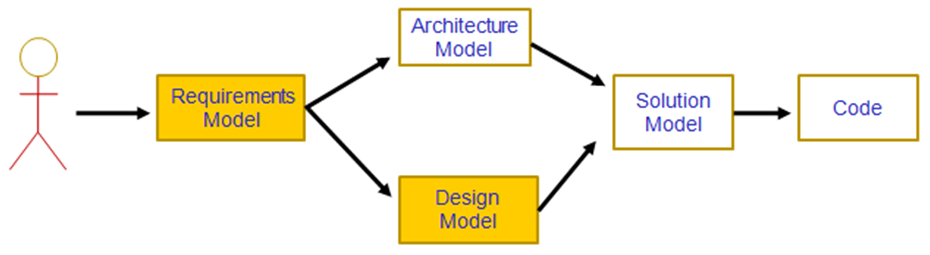
- For each of the models (boxes), the UML has its own models and diagrams. This Module will deal with the UML modelling of the Analysis (Requirements) Model and the Design Model. The order in which the module deals with these UML models will be the order that an analyst might when analysing and designing a system.
- UML diagrams represent two different views:
- Structural (Static) View
- emphasizes the static structure of the system using objects, attributes, operations and relationships.
- Behavioural (Dynamic) View
- emphasizes the dynamic behaviour of the system by showing collaborations among objects and changes to the internal states of objects.
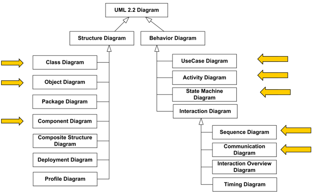
- In this module – we will only cover the following diagrams :
- Structural (Static) View
- Class Diagrams
- Object Diagrams
- Component Diagrams
- Behavioural (Dynamic) View
- Use Case Diagrams
- Activity Diagrams
- State Machine Diagrams.
- Sequence Diagrams
- Communication Diagrams
-
1.6 Start of the Requirements Model
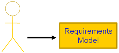
- Stages:
- Analyst finds out what the system must do (Functional Requirements (Use Cases))
- Analyst finds out who and what interact with the system – Actors
- Analyst models this with Use Case diagrams.
- Use Case Diagram
- The 1st UML model that we’ll look at, in the next lecture, is the Use Case model, which includes the Use Case diagram. The Use Case Diagram is very simple with little in the way of notation. It is an effective means of communicating with users, other stakeholders and developers what the system is supposed to do, and who uses it.
-
Lynda.com Videos - Object Oriented Design
- You should watch the following group of Videos :
- Introduction ( 5 Videos )
- 📹 Welcome 1m 25s
- 📹 Who this course is for 1m 15s
- 📹 What to expect from this course 3m 6s
- 📹 Exploring object-oriented analysis, design, and development 1m 41s
- 📹 Reviewing software development methodologies 4m 8s
- 1. Core Concepts ( do NOT view yet - will use later in module)
- 2. Object-Oriented Analysis and Design ( 3 Videos)
- 📹 Understanding the object-oriented analysis and design processes 4m 13s
- 📹 Defining requirements 6m 9s
- 📹 Introduction to the Unified Modeling Language (UML) 1m 54s
- Note that some of these videos mention Objects and Classes - we will cover these soon