08
-
8.0 UML diagrams
- We will look at Two kinds of diagram that are classed as “interaction” diagrams, Sequence diagrams and Communication diagrams (collaboration diagrams). Sequence diagrams show interactions and emphasise the order of the messages over time. Communication diagrams show same interaction in the context of the classes that participate in the interaction and the structural relationships of the classes to one another. We will look at Communication (collaboration) diagrams in the next lecture.
- Dynamic Diagrams
- Activity Diagrams
- Describe the flow of work
- Parallel processing
- Sequence Diagrams
- Describe the sequence of messages passed between objects
- State Machine
- Describe the behaviour of single objects
- State diagrams are closely related to activity diagrams. Activity diagrams describes the flow between areas of work, whereas state diagrams describe the changes between the states of instances. For example, a telephone has different states. It may be ‘hung up’, ‘dialling’, ‘engaged in a call’, or ‘disconnected’. These are states of the phone and we can use a state diagram to link the states together and determine the legal flows through the system. While an item is in a particular state work may or may not be going on, i.e. when you hang up a phone there is no activity in the phone. When making a call there is a lot of activity in the phone. States are therefore useful logical views of an entity.
-
8.1 State Machine
- State diagrams describe the behaviour of a system. They describe all the possible states that a particular object can get into and how the object’s state changes as a result of events that reach the object. In most OO techniques, state diagrams are drawn for a single class to show the lifetime behaviour of a single object. There are many forms of state diagrams, each with slightly different semantics. The UML style is based on David Harel’s statechart.
- A State diagram, also know as Statechart diagram and a Satechart diagram, shows the behaviour of one object and how it changes its state in response to events, together with its responses and actions. They shows the allowable states for objects of a specific class and the permitted transitions between states. They also shows all that possible ways in which objects can respond to events form either other objects, or from outside the system.
- What is a state?
- There are two ways to think about object state:
- The state of an object is a specific collection of attribute values for the object.
- The state of an object describes the behaviour of the object relative to external stimuli.
- An object’s state can be thought of as an abstraction of a particular set of attribute values and links to other objects. The state is derivable from the attributes and links and is of sufficient interest in its own right as to be worth modelling separately.
e.g. a shipment could have status conditions (i.e. states) for waiting to be shipped, in transit and delivered
- To identify states think about the various conditions of an object that need to be reported to the outside world. For example, a shipment should have status conditions (i.e. states) for waiting to be shipped, in transit and delivered. Transitions can be identified from the sequence diagrams, every input message to an object can be considered a transition trigger. Each transition should be associated with a state some transitions will carry out an action and return to the same state.
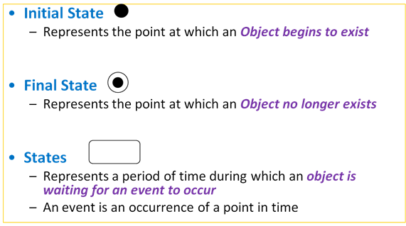
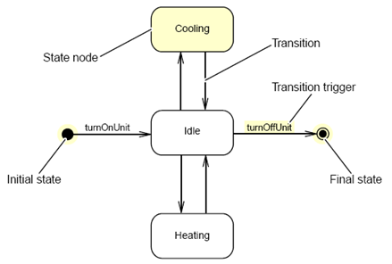
- Notation
- Event
- Triggers a change in State
- Can be a Designated Condition that MUST be TRUE
- Used to label a Transition
- Transitions
- Represents a response to an event
- May cause a change of state or is recursive within the same state
- May invoke operations or transmit events
- A transition links one state with another
- A transition can support an event/action block
-
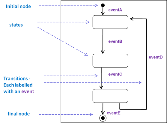
8.2 Examples
- Start :
- Fit the Light Bulb -> ‘Off’ State
- Turn Light Bulb On -> ‘On’ State
- Turn Light Bulb Off -> ‘Off’ State
- While in the ‘On’ State ….
- …… Bulb Burns Out -> End
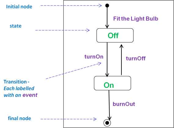
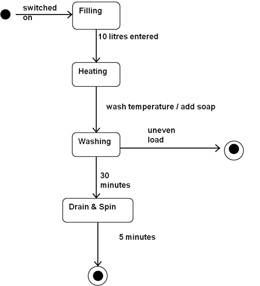
- Example from pervious exam
- In a washing machine’s program there is an object representing the washing cycle. The cycle has a number of states. When the machine is switched on it is in the filling state. Once 10 litres of water have gone into the drum, the heating state begins. When the temperature reaches the “wash temperature” the state becomes washing and soap is added. After 30 minutes of washing the drain and spin state of the cycle is entered. The drain and spin state lasts for 5 minutes. After the 5 minutes is up the washing cycle ends. For safety reasons, an uneven load during the washing state ends the cycle.
- (12 marks)
- Possible solution
-
8.3 Detailed example
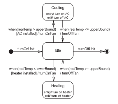
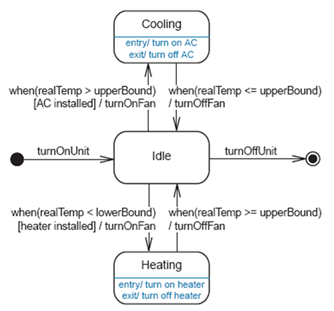
- Will now look at an Example of a detailed state machine diagram. Imagine an Object that controls a Heating, Ventilation and Air-Conditioning system (HVAC). If the Temperature gets too hot – we will turn ON the Air-conditioning and the Fan until it reaches a required temperature – and then they will be switched off. If the Temperature gets too cold – we will turn ON the Heater and the Fan until it reaches a required temperature – and then they will be switched off.
- In detail with specific States...
- If the Temperature gets too hot – we will turn ON the Air-conditioning and the Fan until it reaches a required temperature – and then they will be switched off
- When the outside temperature gets above an UPPER bound ( and air conditioning is installed) - a fan is switched on AND then the air-conditioning is turned on.
(go to Cooling State)
- When the outside temperature gets below the UPPER bound the air-conditioning is turned off AND the fan is switched off.
(go to Idle State)
- If the Temperature gets too cold – we will turn ON the Heater and the Fan until it reaches a required temperature – and then they will be switched off
- When the outside temperature gets below a LOWER bound ( and heater is installed) - a fan is switched on AND then the heating is turned on.
(go to Heating State)
- When the outside temperature gets above the LOWER bound the heating is turned off AND the fan is switched off.
(go to Idle State)
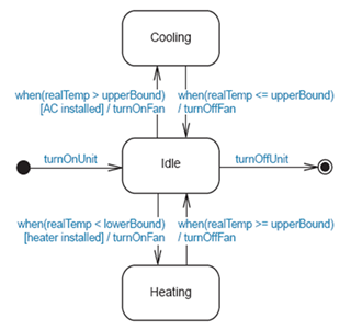
- First go at the State Machine diagram Showing main elements...
- Identifying the Elements of a Statechart Diagram
-
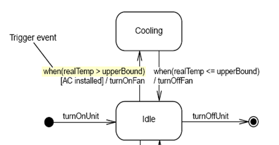
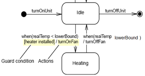
8.4 Event Action Blocks
- Action blocks name the event and say what action is to be take. They are used to label transitions but can also be used within states. When attached to state it means that the state responds to an event with an action that does not cause a transition. This is shown by putting Event Name/Action Name in the state box. The following syntax is used (all parts are optional)
Event [guard]  / action
		or more fully
Event(arg1, arg2) [Guard] / Action(arg1, ...),Action2(arg1, …)
- An event describes stimuli external to an object. An event is used to denote at what point an action is triggered. If a transition has no event within its label, it means that the transition occurs when the activity associated with the state has occurred.
- A guard Is a condition that returns either True or False. A guarded transition will only occur if condition is true. If no event is specified the transition will occur as soon as the guard condition is satisfied. Correct syntax is to place the guard condition between square brackets
- An external event will usually cause a series of internal events to occur, and sometimes these may trigger external events too. For example, a customer depositing a cheque into a savings account will trigger an internal event to place an uncleared credit against the account, and trigger an external event to request transfer of the money by the banking system from the issuer of the cheque.
- To identify the events that affect an entity – primary source of events for objects is the set of use cases. Use cases are groupings of events that provide meaningful functionality for a system and a use case is realised by a group of collaborating objects Examples of events affecting a car sharer – registration, entering a journey, matching of a journey with another car sharer, entering of an agreement, cancellation of an agreement, payment date arriving etc.
- Actions specify behaviour in response to an Event (Transition). Operations are performed in response to messages/events and can occur on a transition between the two states or within some known state.
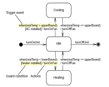
- Our example:
- When the outside temperature gets above an UPPER bound ( and air conditioning is installed) - a fan is switched on AND then the air-conditioning is turned on.
(go to Cooling State)
- When the outside temperature gets below the UPPER bound the air-conditioning is turned off AND the fan is switched off.
(go to Idle State)
- When the outside temperature gets below a LOWER bound ( and heater is installed) - a fan is switched on AND then the heating is turned on.
(go to Heating State)
- When the outside temperature gets above the LOWER bound the heating is turned off AND the fan is switched off.
(go to Idle State)
- A state transition represents a change of state at runtime.
-
8.5 Triggered Actions
- An action corresponds to a function from the functional model and specifies a response to an event. Action can be used for the transition and activity for the state (both are processes typically implemented by some method – but they are treated differently). Actions are associated with transitions and are considered to be processes that occur quickly and are not interruptible. Activities are associated with states and can take longer
- On Entry:
- actions triggered as soon as the state is entered
- On Exit:
- actions triggered as soon as the state is exited
- Do:
- these ongoing actions take place during the lifetime of a state
- On Event:
- these actions take place in response to an event
- Entry/Exit Actions
- Entry/exit actions are defined on states as an alternative to being attached to transitions. Typically entry/exit actions are used when all transitions into a state perform the same action, this results in a more concise description. Entry/Exit actions are preceded by entry/ or exit/. Internal actions do not perform entry or exit actions and an entry or exit action is automatically performed whenever the state is entered or exited respectively. Entry and Exit transitions are shown within the lower state segment with the pseudo event names entry and exit. This is a shorthand which replaces the need to attach the associated event/action block to all transitions either entering or leaving a state.
- An entry or exit action is automatically performed whenever the state is entered or exited respectively. When the outside temperature gets above an UPPER bound ( and air conditioning is installed) - a fan is switched on AND then the “air-conditioning is turned on” -> (go to Cooling State)
- When the outside temperature gets below the UPPER bound the “air-conditioning is turned off” AND the fan is switched off. -> (go to Idle State)
- When the outside temperature gets below a LOWER bound ( and heater is installed) - a fan is switched on AND then the “heating is turned on”
(go to Heating State)
- When the outside temperature gets above the LOWER bound the “heating is turned off “ AND the fan is switched off.
(go to Idle State)
- Complete diagram for the HVAC system:
-
8.6 Creating a Statechart Diagram for an Object
- Possible/Suggested Steps in Creating a Statechart Diagram for an Object:
- 1. Draw the initial and final state for the object.
- 2. Draw the stable states of the object.
- 3. Specify the partial ordering of stable states over the lifetime of the object.
- 4. Specify the events that trigger the transitions between the states of the object. Specify transition actions (if any).
- 5. Specify the actions within a state (if any).
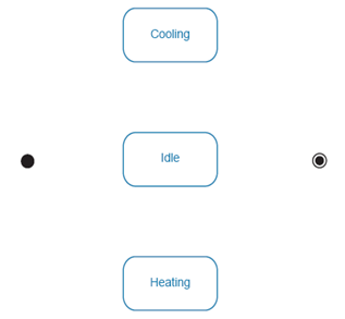
- Step 1 - Start With the Intial and Final States

- Step 2 - Determine Stable Object States
- Step 3 - Specify the Partial Ordering of States
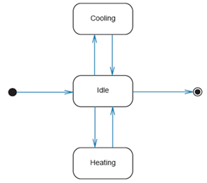
- Step 4 - Specify the Transition Events and Actions
- Step 5 - Specify the Actions Within a State
-
8.7 Composite State & Substates
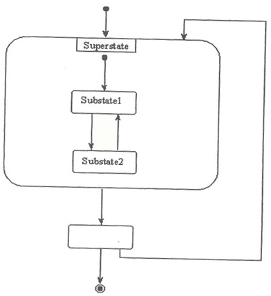
- A Composite state is a complex state that is broken down into substates, each of which inherit the transitions of the parent. A composite state acts as a super container which holds substates and nested sub-state. The substates can be drawn either within the state on the diagram, or in a separate diagram. The following diagram represents a generic composite state which has been included in the original diagram.
- We can specialise a complex state by partitioning it into substates each of which inherit the transitions of the parent. This is the same as specialisation of classes in an inheritance hierarchy- the different substates inherit the properties of the Superstate. A sequential state acts as a super container which holds substates and nested sub-states. Complex state models can be simplified using techniques similar to those of generalisation in class modelling
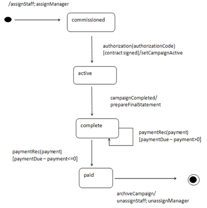
- State Machine example for an Advertising Campaign object:
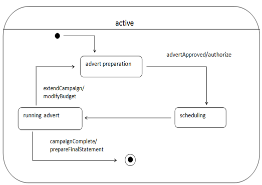
- Example of a Composite State with Substates:
-
2.8 Concurrent Substates (UML@Classroom – chapter 5.5.1 )
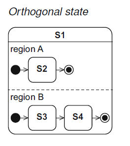
- If a composite state is active, only one of its substates is active at any point in time. If you want to achieve concurrent states, a composite state can be divided into two or more regions, whereby one state of each region is always active at any point in time. This type of Concurrent Substate is also known as an Orthogonal State. Each region of an orthogonal state can have an initial state. A transition to the boundary of the orthogonal state then activates the initial states of all regions. Each region can also have a final state.
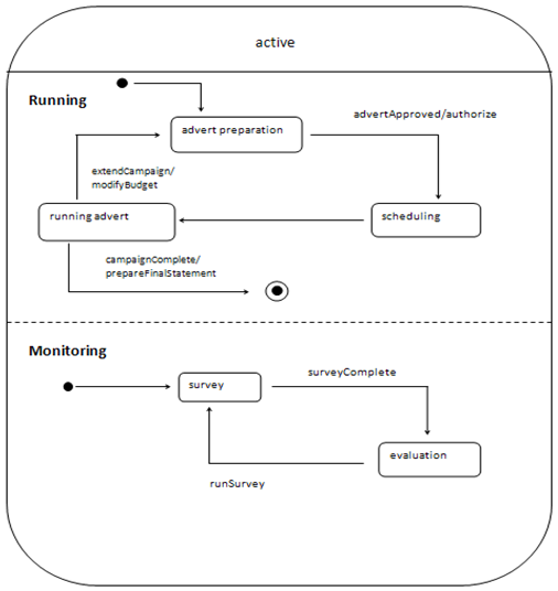
- The ad campaign from the previous section could be “Running” & “Monitoring” at the same time. Running & Monitoring are regions of the “active” composite state:
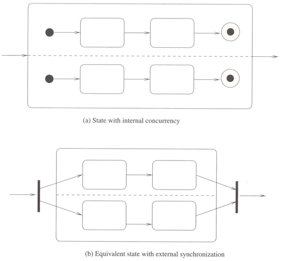
- It's possible for a composite state to consist of multiple, concurrent substates. Partition a diagram into regions with dashed lines, each is a concurrent substate. Each is independent and can occur at the same time-may finish at different times. When the enclosing state is entered, there is one thread of control for each substate. Splitting or merging the concurrent threads can be shown by a synchronisation bar. Concurrent States can be exited in various ways; in these 2 diagrams the state will only be exited when both concurrent regions exit:
- State Modelling Focuses on event driven behaviour over time of objects, belonging to a single class. State diagrams are often under-used and under-valued on real-life projects.
- Examples from previous exams:
- Note how the state refers to a specific class
- Both Examples to be done for next week’s Tutorial (to be decided by nodule leader)
- Also : Sequence Diagram example to be done for next week
-
Produce a State Machine Diagram for the following scenario:
- A university department organises seminars on a number of research topics. These seminars take place in September each year. There is a computer program to help with the administration of these seminars. In the program there is an object representing a seminar, and this Seminar Class has a number of possible states.
- When the seminar is first considered it is in the Proposed state. Once dates, times and rooms for the seminar have been arranged, the seminar's state becomes Scheduled. On the second Monday in August the seminar is advertised and its state changes to Open For Enrolment. When all places are taken the seminar moves to the Full state. If a student drops out (cancels his/her application) the seminar reverts to the Open For Enrolment state. Two days before the start of the seminar, enrolment will be closed (no more applicants will be considered) and the state will change to Closed For Enrolment.
(12 marks)
Produce a State Machine Diagram for the following scenario:
- In a university system the Student Class has a number of states as described below. Draw a state machine diagram for objects of this class.
- When a person submits an application the state is applied. The application is then evaluated and a decision is made to either offer the person a place on a course by sending out an offer letter or to reject them. the student state is changed to offered once the applicant is offered a place on the course. Rejected applicants are not offered a place and a rejection letter is sent out (student state becomes rejected). The student state changes to confirmed when the applicant accepts the place on the course otherwise it is set to declined. After the student has confirmed, a student number is generated one month before the student starts and the state is changed to matriculated, there are then 2 possibilities:
- if the student has passed all the required assessments the state is set to graduated
- if the student withdraws the state becomes withdrawn
(12 marks)