10
-
10.0 Component Diagrams
- The component diagram's main purpose is to show the structural relationships between the components of a system. A component diagram depicts how components are wired together to form larger components and/or software systems. In UML 2, components are considered autonomous, encapsulated units within a system or subsystem that provide one or more interfaces. A component is something required to execute a stereotype function. Examples of stereotypes in components include executables, documents, database tables, files, and library files.
- Although the UML 2 specification does not strictly state it, components are design units that represent things that will typically be implemented using “replaceable” modules. The idea is that you can easily reuse and/or substitute a different component implementation in your designs because a component encapsulates behaviour and implements specified interfaces.
-
10.1 Characteristics of a Component & Uses of Component Diagrams
- Characteristics of a Component
- Component diagrams are useful communication tools for various groups.
- The diagrams can be presented to key project stakeholders. The diagram presents an early understanding of the overall system that is being built.
- Developers find the component diagram useful because it provides them with a high-level, architectural view of the system that they will be building.
- It provides early information about the components and their relationships which allows system administrators to loosely plan ahead.
- Uses of Component Diagrams
- Component diagrams are useful communication tools for various groups. The diagrams can be presented to key project stakeholders and they presents an early understanding of the overall system that is being built. Developers find the component diagram useful because it provides them with a high-level, architectural view of the system that they will be building. It also provides early information about the components and their relationships which allows system administrators to loosely plan ahead.
-
10.2 Drawing a Component & Connecting a Component
- Drawing a component
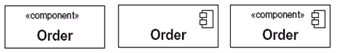
When drawing a component on a diagram, it is important that you always include the component streeotype text (<<component>>) and/or the component icon.
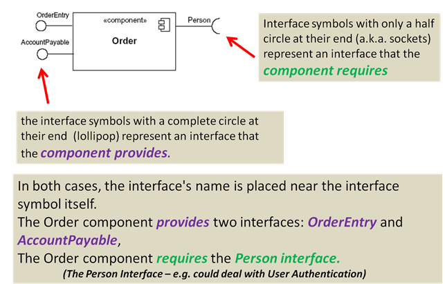
- Connecting Components (Interfaces)
-
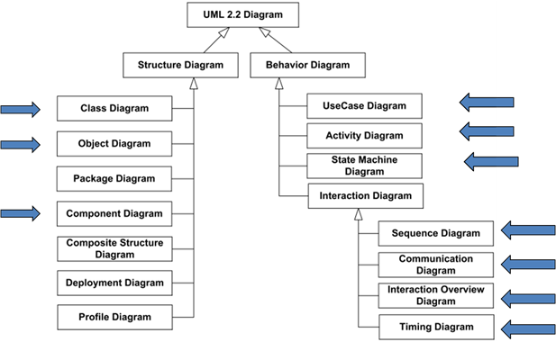
10.3 UML Overview
- The following pictures show how UML diagrams and interrelated each diagrams overall relationship to a system.