Wk 9
-
Control and Instrumentation Systems
- Introduction and Motivation
- Some Definitions: Signals and System
- Instrumentation Systems
- Performance of Measurement Systems
- Example
In this part we shall discuss:- Definitions of Hydraulic and Pneumatic Systems
- Comparisons of Hydraulic and Pneumatic Systems
- Pneumatic System components: Compressors
Introduction and Motivation
- To explain what a mechanical, electrical, chemical, or electrical engineer does is relatively easy, but it is another story to concisely describe the work performed by an engineer who specializes in instrumentation and control. Instrumentation and control are interdisciplinary fields. They require knowledge of chemistry, mechanics, electricity and magnetism, electronics, microcontrollers and microprocessors, software languages, process control, and even more such as the principles of pneumatics and hydraulics and communications. Control and instrumentation engineers (C&I engineers) are responsible for designing, developing, installing, managing and maintaining equipment which is used to monitor and control engineering systems, machinery and processes. Instrumentation and Control covers a range of topics which are important to the monitoring and control of modern systems. Instrumentation and control is a field applicable to many sectors of industry. It enables efficient and safe automatic control of large-scale continuous processes including nuclear power stations, oil refineries and chemical plants down to smaller batch operations such as manufacturing centres, breweries and other food production facilities.
- The characteristics of incompressible liquids:
The motion, which is caused by fluid entering a chamber, is slow but smooth.Because the motion of the output follows the input, the position and the velocity of the output can be accurately controlled.
- The characteristics of compressible liquids:
Since the compressed air tends to expand quickly, the output reaction is fast.However, the compressed air causes the output motion to be jumpy. Hence, it makes pneumatic systems output difficult to control.- Lubrication
Both systems require lubrication to prevent wearing. Hydraulic systems do not require external lubrication because they are self-lubricate systems. On the other hand pneumatic systems do not use oil. So, an oil mist is often added to the air stream to provide lubrication.
Continues on next tab

Actuators used in Instrumentation and Control Systems: Pneumatic Systems
- Actuation Systems
Actuation systems are the elements of control systems which are responsible for transforming the output of a microcontrollers or microprocessor or control system into a controlling action on machine or device. Therefore, an actuator is a component of a machine that is responsible for moving or controlling a mechanism or system.
An actuator moves or controls loads and mechanisms; the actuator is operated by energy namely either pressurised fluid, air or electricity, typically sourced by utilising a pneumatic, hydraulic or electric pump. The energy is then converted into a motion or force to achieve movement or control.
Pneumatic & hydraulic actuation systems
Pneumatic deals with air pressureHydraulic deals with liquid motion and pressure
- Comparisons
Both hydraulics and pneumatics are defines as fluid power. They use fluid to transmit power from one point to another. In physics, a fluid is a substance that continually deforms (flows) under an applied shear stress. Fluids are a subset of the phases of matter and include liquids, gases, plasmas, and to some extent, plastic solids.
In many ways, hydraulics and pneumatics share the same principles. However, there are a few ways in which they differ.- Transmission of power
The power in both systems is transferred through fluid. But the oil used in hydraulic systems is incompressible, similar to a solid.Pneumatic systems use air. Air is compressible like a spring.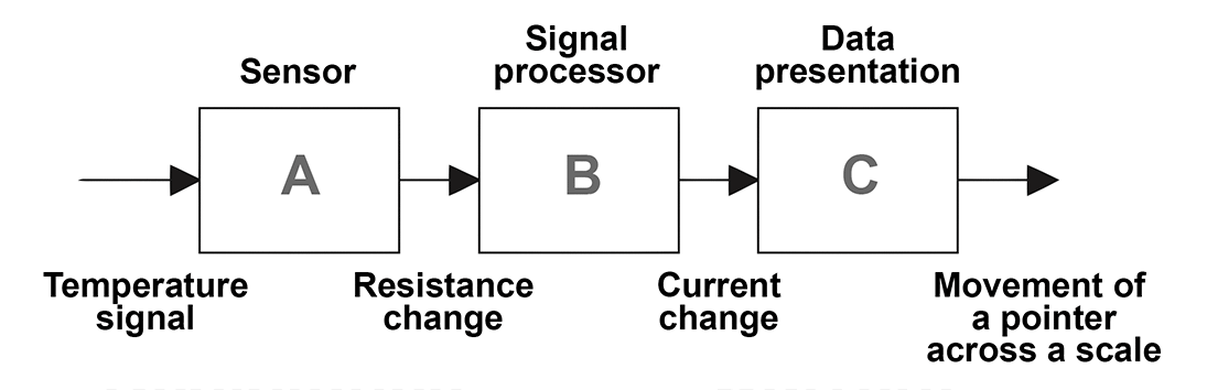
- The characteristics of incompressible liquids:
Accumulator
 Accumulator is a container in which the oil is held under pressure against an external force, which involves gas within a bladder in the chamber containing the hydraulic fluid.If the oil pressure rises, then the bladder contracts increase the volume the oil can occupy and so reduces the pressure.If the oil pressure falls, the bladder expands to reduce the volume occupied by the oil and so increases its pressure.
Typical Pneumatic System
- Pneumatic technology deals with the study of behavior and applications of compressed air in our daily life in general and manufacturing automation in particular. Pneumatic systems use air as the medium which is abundantly available and can be exhausted into the atmosphere after completion of the assigned task.
Continues on next tab
Actuators used in Instrumentation and Control Systems: Pneumatic Systems (cont.)
- Precision
Precision is the fineness to which an instrument can be read repeatably and reliably. The term precision is used to describe the degree of freedom of a measurement system from random errors. Thus, a high precision measurement instrument will give only a small spread of readings if repeated readings are taken of the same quantity. A low precision measurement system will give a large spread of readings.
- Power supply
In a hydraulic system, a pump must be turned on to cause the fluid to flow. Where as, in a pneumatic system, compressed air confined in a tank is released to cause the fluid to flow.
Typical Hydraulic Power Supply
 With a hydraulic system, pressurized oil (fluid) is provided by a pump driven by an electrical motor.The pump pumps oil from a sump through a non return valve and an accumulator to the system, from which it return to the sump.The pressure relief valve is to release the pressure if it rises above a safe level.The accumulator is to smooth out any short term fluctuations in the output oil pressure.
2 Sets of Reading obtained by 2 different measurement devices of the same quality Instrument 1 20.1mm 20.2mm 20.0mm 20.1mm 20.1mm 20.1mm 20.0mm Instrument 2 19.9mm 20.3mm 20.0mm 20.5mm 20.2mm 19.8mm 20.3mm
- Pneumatic technology deals with the study of behavior and applications of compressed air in our daily life in general and manufacturing automation in particular. Pneumatic systems use air as the medium which is abundantly available and can be exhausted into the atmosphere after completion of the assigned task.
Receiver Tank size
- There is no generally accepted method of sizing air receivers but a commonly used formula is based on the mass balance: \[ V=t C p_a /(p_1-p_2) \] where \(t\) is the time for the receiver to go from upper to lower pressure limits (min), \(C\) is the free air needed (scfm), \(V\) volume of the receiver tank (cu ft), \(p_a\) is the atmospheric pressure (\(14.7\)psia), \(p_1\) is the maximum tank pressure (psia), and \(p_2\) is the minimum tank pressure (psia).
 Symbol used in block diagrams
- Example
For an air compressor system with mean air consumption \(1000\)cfm, maximum tank pressure \( 110\)psi, minimum tank pressure \(100\) psi and \(5\) sec time for the receiver to go from upper to lower pressure, the volume of the receiver tank can be calculated by \[ V=t C p_a /(p_1-p_2) = 5 \times \frac{1}{60} \times 1000 \times 14.7 \times (110-100)=122ft^3 \]
 Since the graph has a slope of 10 mm/kg, the sensitivity is 10.
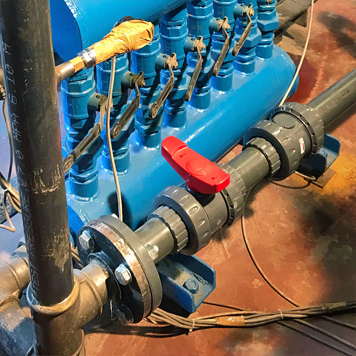
Basic Components of Pneumatic System
Air Intake Filters are used to filter out the contaminants from the air.Air is generated by using air compressors. Air compressors are either diesel or electrically operated.Since the air compressor increases the temperature of the air, an intercooler is used to reduce the temperatureThe water vapor or moisture in the air is separated from the air by using a dryer.Receiver Tank
- An air receiver is essential to every compressed air system to act as a bu↵er and a storage medium between the compressor and the consumption system.
The air is compressed slowly in the compressor. But since the pneumatic system needs continuous supply of air, this compressed air has to be stored. The compressed air is stored in an air receiver.
The air receiver smoothens the pulsating flow from the compressor. It also helps the air to cool and condense the moisture present. The air receiver should be large enough to hold all the air delivered by the compressor. The pressure in the receiver is held higher than the system operating pressure to compensate pressure loss in the pipes.
- There is no generally accepted method of sizing air receivers but a commonly used formula is based on the mass balance: \[ V=t C p_a /(p_1-p_2) \] where \(t\) is the time for the receiver to go from upper to lower pressure limits (min), \(C\) is the free air needed (scfm), \(V\) volume of the receiver tank (cu ft), \(p_a\) is the atmospheric pressure (\(14.7\)psia), \(p_1\) is the maximum tank pressure (psia), and \(p_2\) is the minimum tank pressure (psia).
Piston Type, Double Acting compressor
 The pulsation of air can be reduced by using double acting compressor as shownAs the piston moves, the air is compressed on one side whilst on the other side of the piston, the air is sucked in.Due to the reciprocating action of the piston, the air is compressed and delivered twice in one piston stroke. Pressure higher than 30bar can be produced.For more information about 'Double acting cylinder compressor' click on the following link : url
Piston Type, Multi-stage compressor
As the pressure of the air increases, its temperature rises. It is essential to reduce the air temperature to avoid damage of compressor and other mechanical elements.Intercooler is used to reduce the temperature of compressed air during the compression stages. The inter-cooling reduces the volume of air which used to increase due to heat. The compressed air from the first stage enters the intercooler where it is cooled.This air is given as input to the second stage where it is compressed again.The multi-stage compressor can produce a pressure of around 50bar.For more information about 'Double acting cylinder compressor' click on the following link : url
Continues on next tab
Since the graph has a slope of 10 mm/kg, the sensitivity is 10.
Compressor
- The piston compressor (sometimes also called reciprocating compressor) is by far still the most common type of air compressor in use in industry today. It is available in wide range of types and sizes. It is a mechanical device which converts mechanical energy into fluid energy. The compressor increases the air pressure by reducing its volume which also increases the temperature of the compressed air. It is capable of compressing iar up to 1200kPa (12bar) as a single stage compressor and up to 14000kPa (140)bar as a multi-stage compressor.
Pneumatic Compressor Types
- In the positive displacement type, a specified quantity of air is trapped in a compression chamber and the volume which it occupies is mechanically reduced, causing a corresponding rise in pressure prior to discharge.
Positive Displacement Compressors:
Piston Type, Single Acting Compressor The simplest form is single acting cylinder compressor.It produces one pulse of air per piston stroke. As the piston moves down during the inlet stroke the inlet valve opens and air is drawn into the cylinder.As the piston moves up the inlet valve closes and the exhaust valve opens which allows the air to be expelled.The valves are spring loaded.The pressure developed is about 3-40 bar.For more information about 'Single acting cylinder compressor' click on the following link : url
Screw Compressor
 For medium flow and pressure applications, screw compressor can be used.It is simple in construction with less number of moving parts. The air delivered is steady with no pressure pulsation.It has two meshing screws. The air from the inlet is trapped between the meshing screws and is compressed.The contact between the two meshing surface is minimum, hence no cooling is required.These systems are more common then piston type since they are much cheaper.
Vane Compressor
The unbalanced vane compressor consists of spring loaded vanes seating in the slots of the rotor.The pumping action occurs due to movement of the vanes along a cam ring. The rotor is eccentric to the cam ring. As the rotor rotates, the vanes follow the inner surface of the cam ring.The space between the vanes decreases near the outlet due to the eccentricity. This causes compression of the air.These compressors are free from pulsation. If the eccentricity is zero no flow takes place.
Continues on next tab
Since the graph has a slope of 10 mm/kg, the sensitivity is 10.
Piston Type, Combined Multi-stage compressor
 In this type, two-stage compression is carried out by using the same piston.Initially when the piston moves down, air is sucked in both through the inlet valve and the intercooler.During the compression process, the air moves out of the exhaust valve into the intercooler.As the piston moves further the stepped head provided on the piston moves into the cavity thus causing the compression of air.Then, this is let out by the exhaust port.
Diaphragm Compressor
 These are small capacity compressors. In piston compressors the lubricating oil from the pistons walls may contaminate the compressed air. The contamination is undesirable in food, pharmaceutical and chemical industries.For such applications diaphragm type compressor can be used.The piston reciprocates by a motor driven crankshaft. As the piston moves down it pulls the hydraulic fluid down causing the diaphragm to move along and the air is sucked in.When the piston moves up the fluid pushes the diaphragm up causing the ejection of air from the outlet port. Since the flexible diaphragm is placed in between the piston and the air no contamination takes place.
 Axial Compressor
 Centrifugal Compressor
Youtube Centrifugal Compressor video
Since the graph has a slope of 10 mm/kg, the sensitivity is 10.
Lobe Compressor
 The lobe compressor is used when high delivery volume but low pressure is needed. It consists of two lobes with one being driven and the other driving.The animation above shows the construction and working of Lobe compressor. It is similar to the Lobe pump used in hydraulic systems.The operating pressure is limited by leakage between rotors and housing. As the wear increases during the operation, the efficiency falls rapidly.
Dynamic Compressors (Turbo Compressor)
When very large volume of compressed air is required in applications such as ventilators, combustion system and pneumatic powder blower conveyors, the dynamic compressor can be used.There are 2 main types of dynamic compressor, they are centrifugal and axial.Centrifugal systems use centrifugal force to hurl air out from the fins, centrifugal systems can generally obtain greater pressures than the axial type compressor.Axial type compressor use a set of fan blades in line to generate large air flow, pressures from this method aren’t expected to reach much over 0.5bar. The axial compressors are largely used for ventilation and as part of air processing.The pressure needed is very low in such applications.The impeller rotates at a high speed. Large volume of low pressure air can be provided by blowers.The blowers draw the air in and the impeller flings it out due to centrifugal force.Positive displacement compressors need oil to lubricate the moving parts, whereas the dynamic compressors have no such need.
-
Summary
-
Tutorials
dfdfdfd