-
Introduction to Programmable Logic Controllers (PLC's)
- PLC's have been used in industry in one form or another for the last 30 years. The newest models may not resemble their earlier counterparts but many of the concepts in the first units are still in use.
- A PLC is a user-friendly, microprocessor- based specialized computer that carries out control functions of many types and levels of complexity. It is programmed using a programming panel or keyboard. They are typically used to control the operating sequence of machines, production lines and industrial processes.
- Its purpose is to monitor crucial process parameters and adjust process operations accordingly.
- They are dedicated to receiving input signals and transmitting output signals in response to the program stored in the microprocessors memory.
- They are used extensively because the PLC is easy to set up and program.
- It can be programmed (to a degree), controlled, and operated by a person unskilled in operating (programming) computers.
- Essentially, a PLC's operator draws the lines and devices of ladder diagrams with a keyboard/mouse onto a display screen.
- The resulting ladder diagram is converted into computer machine language and run as a program.
-
Disadvantages of using PLC's
Some applications are single-function applications. It does not pay to use a PLC that includes multiple programming capabilities if they are not needed. Their operational sequence is seldom or never changed, so the reprogramming available with the PLC would not be necessary.In relay systems, the stop button electrically disconnects the circuit; if the power fails, the system stops. This, of course, can be programmed into the PLC; however, in some PLC programs, you may have to apply an input voltage to cause a device to stop. These systems may not be fail-safe.General Connection of PLC to a process
General PLC Control Loop
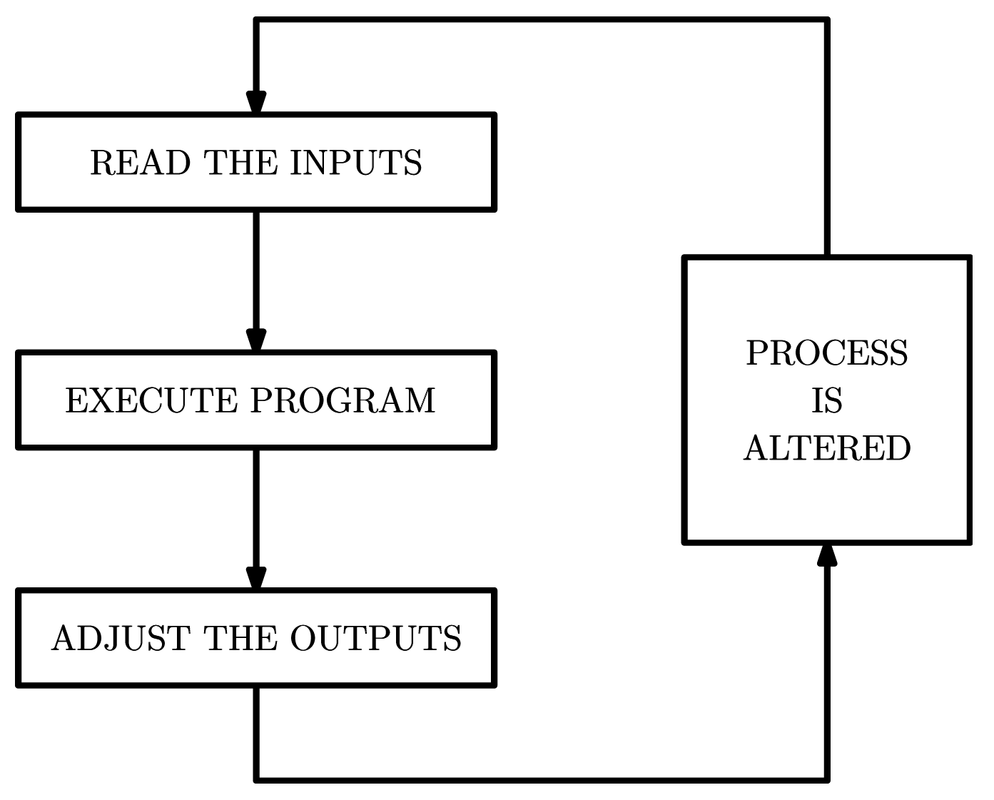 Figure: General PLC control loop.
The program reads the inputsThe outputs are operated according to the instructions in the program.The actuator alter the process, hence the inputs to the PLC change.The loop is repeated every few milliseconds.
Example: Temperature Control System via PLC
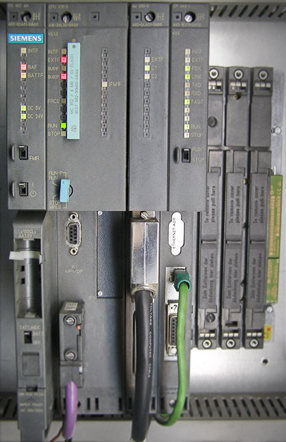
Common PLC Brands
Allen BradleySiemensABBOmronMitsubishiRockwellSchneider ElectricTelemechanique
The smallest PLC's have six input ports and six output ports, they are typically used to control a single machine on a factory floor. They cost approximately £100. The largest PLC's have several thousand input and output ports and can cost tens of thousands of pounds.
Advantages of using PLC's
- They are flexible:
In the past, each different electronically controlled production machine required its own controller; 15 machines might require 15 different controllers.Now it is possible to use just one model of a PLC to run any one of the 15 machines.Furthermore, you would probably need fewer than 15 controllers, because one PLC can easily run many machines.Each of the 15 machines under PLC control would have its own distinct program (or a portion of one running program).
- Implementing Changes and Correcting Errors:
With a wired relay-type panel, any program alterations require time for rewiring of panels and devices.When a PLC program circuit or sequence design change is made, the PLC program can be changed from a keyboard sequence in a matter of minutes.No rewiring is required for a PLC-controlled system.Also, if a programming error has to be corrected in a PLC control ladder diagram, a change can be typed in quickly.– For example consider the automotive industry which is faced annually with major changes in production as new models are designed. This changeover previously required electricians and maintenance personnel to work long hours rewiring machinery. Each changeover period was costly. The PLC's were therefore developed to ease these changeover problems.
- Large Quantities of Contacts:
Different from relay-based panel systems, PLC's do use software contacts which allows them to use large quantities of contacts at the same time. This reduces the costs considerably.Suppose that a panel-wired relay has four contacts and all are in use when a design change requiring three more contacts is made. Time would have to be taken to procure and install a new relay or relay contact block. But, using a PLC, however, only three more contacts would be typed in. Contacts are now a “software” component.
- Lower Cost:
Increased technology makes it possible to condense more functions into smaller and less expensive packages.Now you can purchase a PLC with numerous relays, timers, and counters, a sequencer, and other functions for a few hundred pounds.A PLC programmed circuit can be evaluated in the lab. The program can be typed in, tested, observed, and modified if needed, saving valuable factory time.
- Visual Observation:
A PLC circuit's operation can be seen during operation directly on a CRT screen.The operation or mis-operation of a circuit can be observed as it happens.Logic paths light up on the screen as they are energized.Troubleshooting can be done more quickly during visual observation.
- Ladder or Boolean Programming Method:
The PLC programming can be accomplished in the ladder mode by an engineer, electrician or possibly a technician. Alternatively, a PLC programmer who works in digital or Boolean control systems can also easily perform PLC programming.
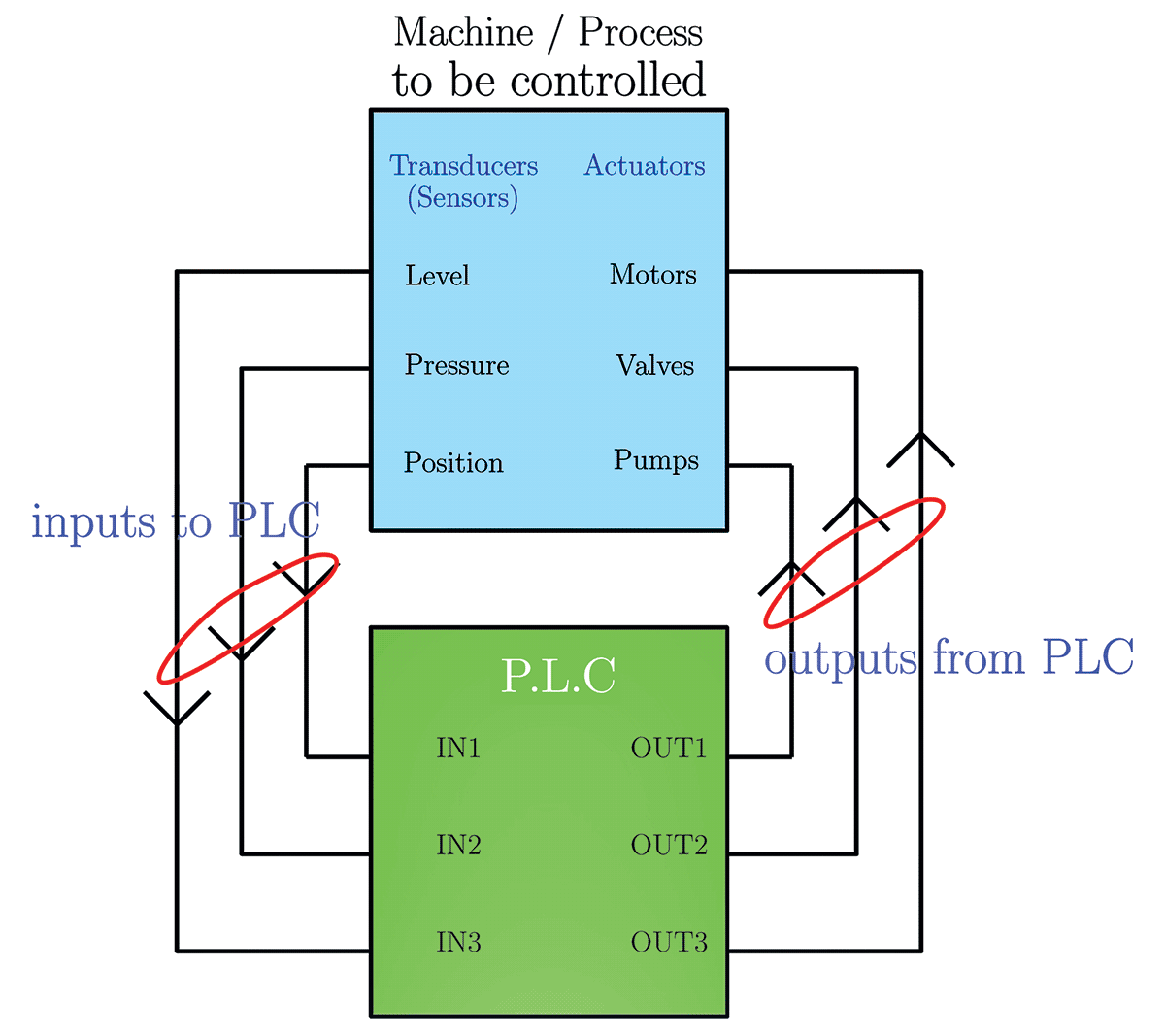
General Connection of PLC to a process
Figure shows in general how a PLC is connected to a machine/processTransducers are positioned at strategic locations on the process to be controlled. The output of transducer is usually conditioned to be logic signal (i.e. +5V, +12V or +24V and 0V)Each transducer is connected to an input (IN1, IN2, etc) of the PLCEach output of the PLC (OUT1, OUT2, etc) is connected to an actuator on the process
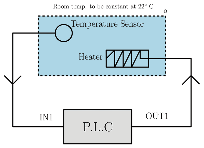
Example: Temperature Control System via PLC
Figure shows how a PLC is used to control the temperature of the room at a constant $22^\circ$CThe temperature sensor sends $+5V$ to IN1 of the PLC when the temperature is above $+22^\circ$ and $0$ Volts when below $+22^\circ$.The program in the microprocessor of the PLC reads IN1. If IN1 is $0$Volts, OUT1 is activated, switching on the heater and this heats the room and eventually the temperature sensor will be above $22^\circ$C. The signal at IN1 of the PLC will then change to $5$Volts. The program then switches OUT1 off, the room cools down and IN1 will eventually become $0$Volts again. This is repeated over and over to keep the room around $22^\circ$C.- Note: A PLC would not be used for a single input, single output system application like this. But it does describe the basic concept.
-
Display Device
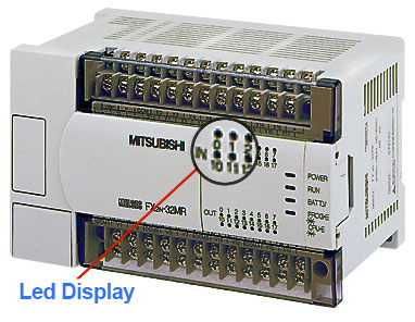
Figure: PLC LED Display for Inputs / Outputs
The figure above shows a typical PLC display. Applying $+24V$ to IN1 will illuminate LED associated with this input. $0V$ will turn the LED off. Similarly if an output relay is energised, the associated LED will be illuminated.
Power Supply and Programming Panel
- Power Supply
The power supply provides the +5 Volts and 0 Volts to the microprocessor / CPU, memory, input circuits, output circuits and programming panel / keyboard.
- Programming Panel / Keyboard
This is used to enter a program into the microprocessor memory. The operating sequence of a machine or process is controlled by these programs. To alter a process simply edit the existing program or enter a new program. The keyboard or keypad is often a separate unit which plugs into the rest of the PLC system, since the keyboard is used infrequently. This reduces cost.
The Architecture of a PLC
- This chapter describes the design, structure and operation of a programmable logic controllers internal components. All PLC's have microprocessor (Central Processing Unit), memory to store program code and instructions, and input/output circuits.
Input Module
📷 The most common input interface circuit uses an opto-coupler arrangement such as that shown in figure. Each input channel(port) (IN $i$) of input module has its own individual configuration. An opto-coupler is a device which uses light to couple signals from one system to another; in this case the input transducer and the microprocessor circuit. In incorporates a light emitting diode (LED) and a photo transistor for this purpose. The device provides a very large degree of electrical isolation between the transducer side and the CPU since each part has their different grounds.
When +24V DC is applied to the input port (IN$i$), a current of approximately $20mA$ flows through the opto-coupler LED causing it to emit light and so turn on the photo transistor. When the photo transistor ON, current flows through the resistance $R$, the display LED and the transistor. So the display LED lights up. Thus it informs us that an input is applied (IN$i$=Logic $1$). The collector voltage becomes approximately $0V=$Logic $0$. Then the output of the inverter will be Logic 1 which is same with the input channel. When the voltage in the channel changes to $0V$, the opto-coupler will turn off together with the display LED. Hence the input to the inverter will be $+5V$ and the output to the microprocessor circuit will be $0V$ which is nothing but the applied voltage to the transducer.Output Module
Most PLC output modules use relay circuits. A traditional relay is a switched controlled by an electro-magnet. Relays are used in PLC's because they can handle large currents and offer high degree of isolation between the PLC circuits and the load circuits.
📷 A typical relay will be capable of switching a few amps. A typical electro-magnet relay based output circuit is shown in this figure.
The transistor switches current through the relay coil to close its contacts. The transistor is operated by the microprocessor. Each output has associated with a display led (part of display component) which lights up when the output relay contacts are closed. $+Vcc$ is the voltage supplied to the relay contacts and this will be the voltage supplied to the actuator when the relay contacts close. On some PLC's, it is possible to connect different supply voltage to each output.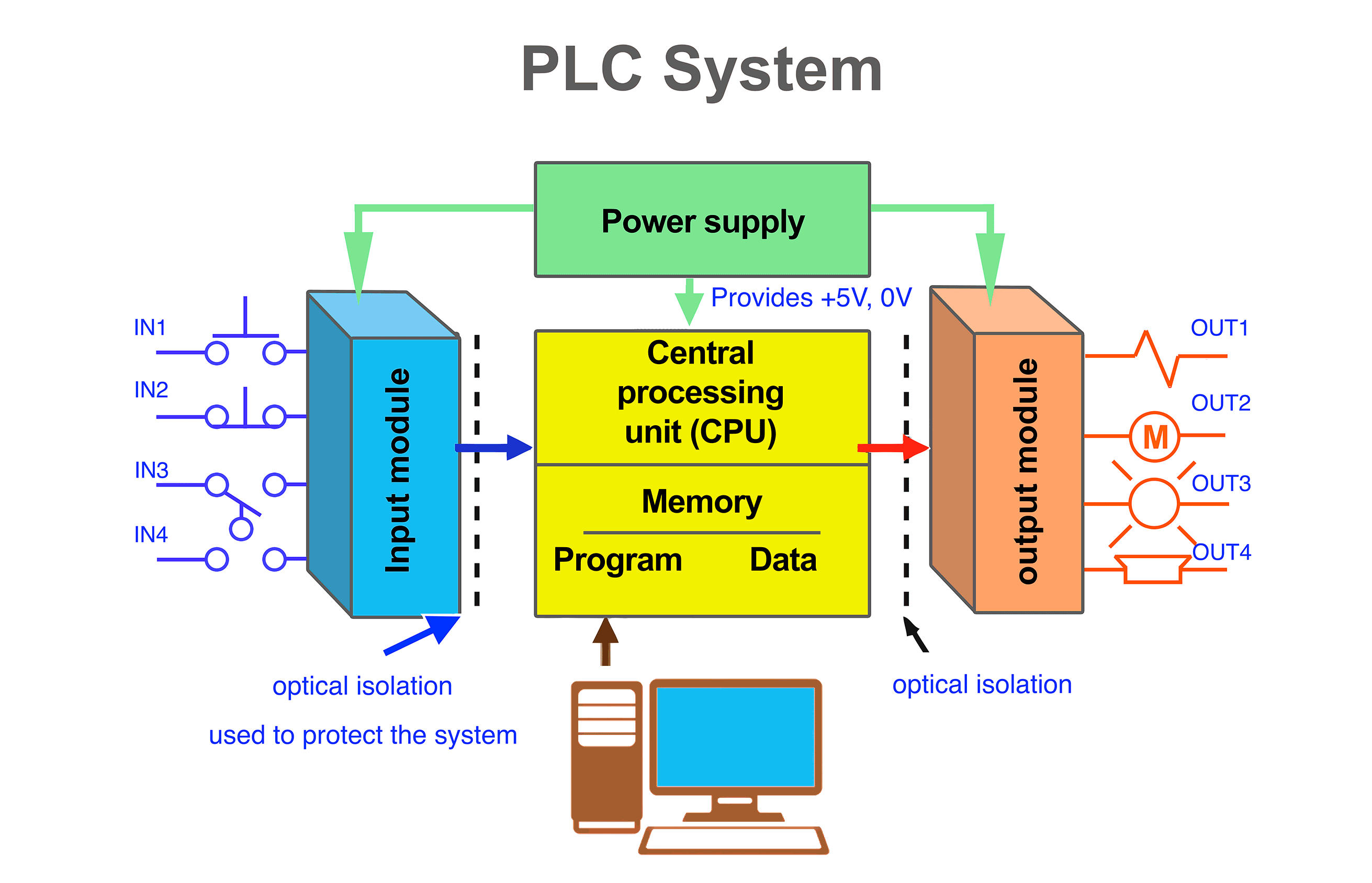
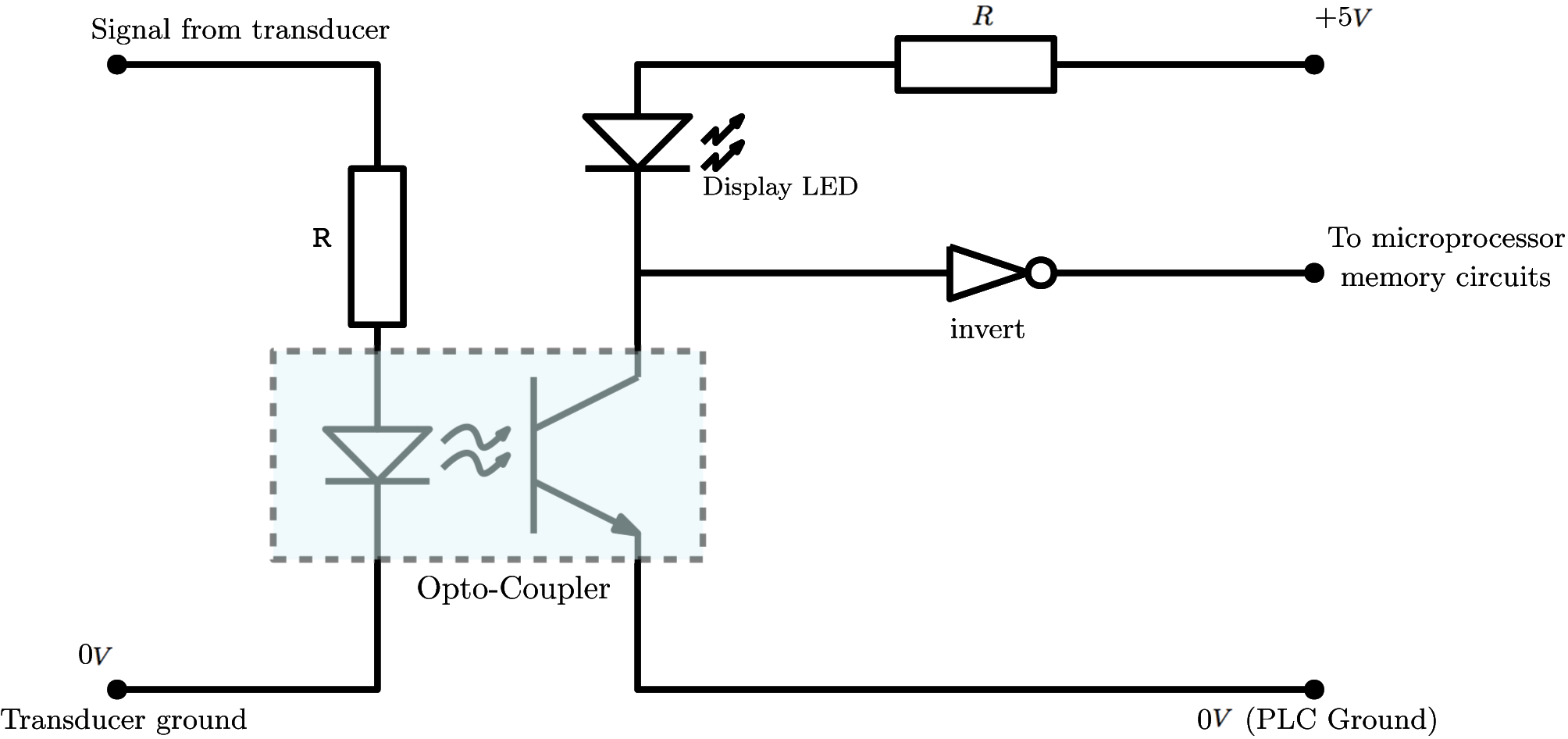
Figure: Input Module

Figure: Output Module
-
Differences between electrical circuit ladder diagrams and PLC ladder diagrams
- The power supply is not included in the ladder diagram program
- Each rung must start with normally open and normally closed contacts and must be terminated with an output
- There must always be one output on each rung. An output is, for example, a PLC output relay, timers, counters etc.
- Each line of the ladder diagram program is known as a rung.
- The last rung must be an END statement
- Other elements such as timers, counters, ADC's and DAC's and shift registers can be incorporated into ladder diagram
- The best way to explain ladder diagrams, and ladder programs, is using worked examples which compare conventional control methods with PLC control.
Example 1: Normally Open Contacts
- 📷 The figure shown here is a practical example which uses normally open contacts in the ladder diagram
Example 2: Normally Closed Contacts
- 📷 Figure shown here is a practical example which uses normally closed contacts in the ladder diagram
Note on ladder programs
- LOAD instruction is used to read the PLC inputs, or to be more precise the input memory registers contents.
- OUT instruction sets the output memory register (and hence PLC outputs)
- NOT instruction is used in conjection with LOAD to define normally closed contacts
- END instruction is always used on the last line of the program, when this instruction is reached, the program returns to line 0 to repeat the same flow again.
Continues on next tab
Figure: Relay Systems and Equivalent PLC symbolsLadder Diagram Program
- The electrical circuits of processes and machines can be drawn in ladder diagram form. These ladder diagrams are then be converted into a program which is entered into the memory of a PLC. This process is known as ladder diagram programming. The original electrical circuit can be replaced bt the PLC.
- The ladder diagram which are created to program PLC are slightly different from those shown in the previous page. A typical ladder diagram program is shown in figure.
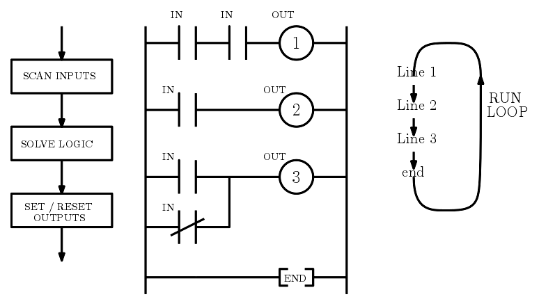
Figure: PLC Ladder Diagram PrograLm
Example 1: Normally Open Contacts
- Figure shows a practical example which uses normally open contacts in the ladder diagram
- When the switch is closed, $+24V$ is connected to IN1 of the PLC. This closes the contacts IN1 of the ladder diagram to energise control relay RC1 and hence turn load ON.
- If the switch is opened again, the contacts IN1 will spring open de-energising relay RC1 turning load OFF.
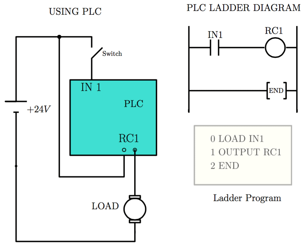
Figure: Normally Open contacts: The input contacts (IN1 etc) are not real contacts, they are part of the program.
Example 2: Normally Closed Contacts
- Figure shows a practical example which uses normally closed contacts in the ladder diagram
- Initially control relay RC1 is energised through normally closed contacts IN1.
- When the switch is closed, contacts IN1 will open de-energising control relay RC1 and switching OFF the load.
- When the switch is opened, contacts IN1 return to their normally closed state, hence RC1 is energised and the load is ON.
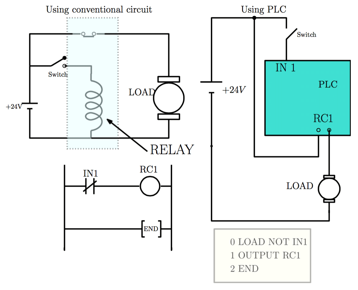
Figure: Figure: Normally Open contacts: The input contacts (IN1 etc) are not real contacts, they are part of the program.Relay system and the equivalent PLC ladder symbols
- 📷 Programmable Logic Controllers are programmed using Ladder Diagram techniques and the symbols used are based on relays as shown in this figure. When the switch is closed, the relay coil is energised, producing a magnetic field. This magnetic field pulls the relay contacts and the normally open (NO) contacts are pulled to close, whereas normally closed (NC) contacts are pulled to open. When the switch is opened, the relay coil is de-energised and the contacts spring back to their original states.
Ladder Diagram Circuits
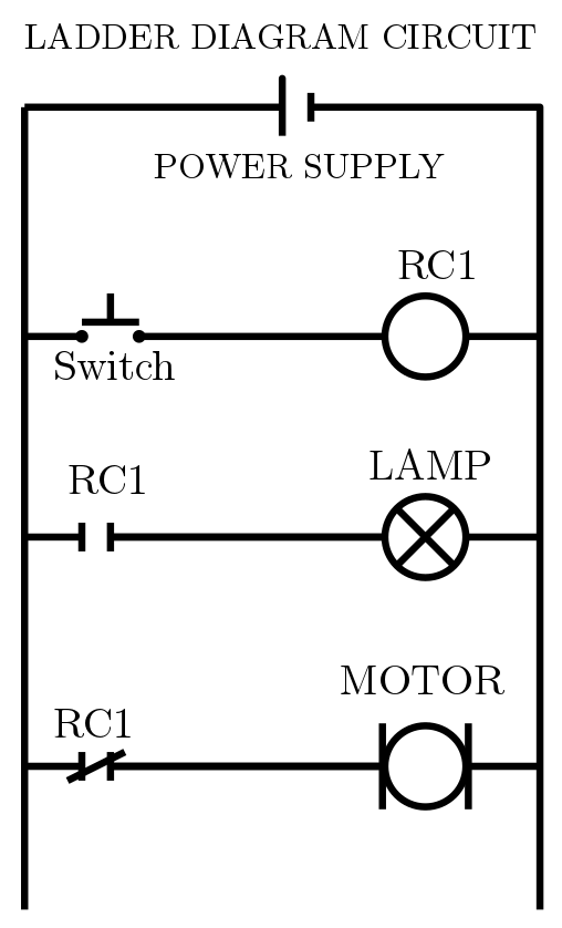
- Ladder diagrams are an alternative way of drawing electrical circuit diagrams. Figure shows an example of a ladder diagram.When the system is started, or energised, only Motor turns. When the switch is pressed, relay coil RC1 is energised and its associated contacts change state. The normally open (NO) contact will close, turning the lamp on. The normally closed (NC) contact in the last rung will open turning off the motor. Opening the switch, will de-energise the relay coil (RC1) and return the contacts to their original states, switching off the lamp and turning on the motor.
Ladder Diagram Program
- 📷 Ladder Diagram Program

-
Timers
- Why do we need them?
In many control tasks there is a need to control the time running in the process. For example, a robot or a cylinder might need to be controlled to operate for a particular interval of time, or perhaps be switched on after some time interval. PLCs thus have timers as built-in devices.
Timers count seconds or fractions of a second by using internal microprocessor clock. They are used to delay the operation of PLC outputs or to hold outputs energised for a preset time. The pre-set value of a timer is the delay period required in the process and is typically in the range $0.1-999$ seconds in steps of $0.1$ seconds.Example 10: Delay in Operation of an Output
- 📷 Example 10: Figure here shows a timer being used to delay turning on lamp 1 and delay turning off lamp 2.
Example 11: Operating an Output for a Pre-set Time
- 📷 Example 11: Figure here shows how a PLC output can be turned ON for a pre-set time before being turned OFF.
Example 12: Sequencing outputs using timers
- 📷 Example 12: The ladder diagram shows how to use 3 timers to repeatedly energise and de-energise control relays RC1, RC2 and RC3 one after the other as indicated in the timing diagram shown in the next slide.
Example 12b: Timing diagram and the code for PLC
- 📷 Example 12b: Timing diagram and the code for PLC
Example 3: Logical AND Function (Contacts in Series)
- Figure shows an AND function.
- When Switches SW1 AND SW2 are closed IN1 AND IN2 contacts close energising the control relay RC1 turning ON the load.
- It is important to note that closing only one switch will not turn on the load.
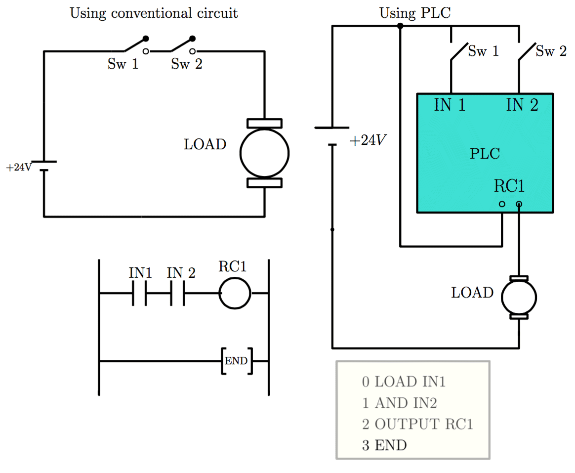
Figure: Logical AND with PLC software
Example 4: Logical OR Function (Contacts in Parallel)
- Figure shows an OR function.
- When Switches Sw1 OR Sw2 are closed IN1 OR IN2 contacts close energising the control relay RC1 turning ON the load.
- It is important to note that closing only one switch is sufficient to turn on the load.
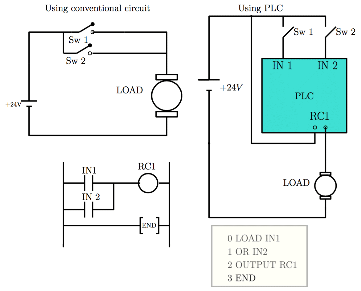
Figure: Logical OR with PLC software
Example 5: Combined Logical AND and OR Functions (Contacts in Parallel & Series)
- Figure shows an example which uses combinations of normally open contacts, normally closed contacts, AND and OR functions.
- Closing Sw1 or Sw2 will close contacts IN1 OR IN2 respectively and the control relay RC1 will be energised through the normally closed contacts IN3, turning ON the load
- When Sw3 is closed IN3 contacts will open so the load will be turned OFF.

Figure: Combined Logical AND and OR with PLC software
Example 6: Multiple Outputs
- In the ladder programming, it is possible to connect more than one control relay to a contact.
- This allows one input to energise more than one output.
- Figure shows an example of this case

Figure: Multiple outputs case.
Example 7: Coil Feedback
- A control relay can be associated with a contact with the same label. When the control relay is energised, its associated contact changes state.
- Figure shows an example of this. When the switch is closed, IN1 contacts are closed and the output control relay RC1 is energised. As soon as the control relay RC1 is energised, its associated input contacts are also closed energising RC2.
- The load is therefore turned ON. Opening the switch will de-energise control relay RC1 hence opening contacts of RC1 and turning the load OFF.
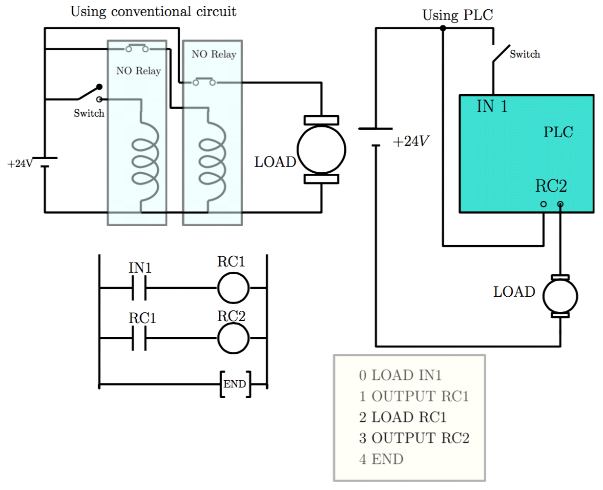
Figure: Coil feedback system: Note hat RC1 is an internal (software) relay and not associated with a physical input or output
Example 8: Latch Circuit
- A latch circuit is used to hold a control relay energised even if the input contact which energised it turned off. An example of a latch circuit is shown in the figure below.
- When the switch is closed, IN1 contacts are closed and the relay coil RC1 is energised. The Load is turned ON and contacts of RC1 are also closed. Control relay RC1 is now also energised through the input contacts of RC1. If the switch is now opened, IN1 contacts will open, but control relay RC1 will remain energised through contacts RC1. The load therefore remains turned ON.
- The output is said to be LATCHED ON.

Figure: Latch Circuit and the corresponding PLC ladder diagram.Example 9: Breaking the Latch Circuit
- Figure shows how to break a latch circuit. When the switch Sw1 is closed momentarily, contact IN1 closes momentarily and control relay RC1 is latched on.
- To break this latch circuit, close switch Sw2 to open contacts IN2 de-energising control relay RC1 and hence opening input contacts RC1.

Figure: Latch Circuit and the corresponding PLC ladder diagram.
Example 10: Delay in Operation of an Output
- Figure shows a timer being used to delay turning on lamp 1 and delay turning off lamp 2.
- Timers normally open (NO) and normally closed (NC) contacts are connected to RC1 and RC2.
- Initially RC1 is de-energised and RC2 is energised. Hence, lamp 1 is off, lamp 2 is ON. When the switch is closed, IN1 contacts are closed energising T1. Timer T1 has a pre-set delay of 5 sec. 5 seconds after the timer is energised, its associated contacts change state. RC1 is energised and Lamp 1 is turned ON, RC2 is de-energised and Lamp 2 goes OFF. Opening the switch will reset the timer and its contacts back to their original de-energised states.
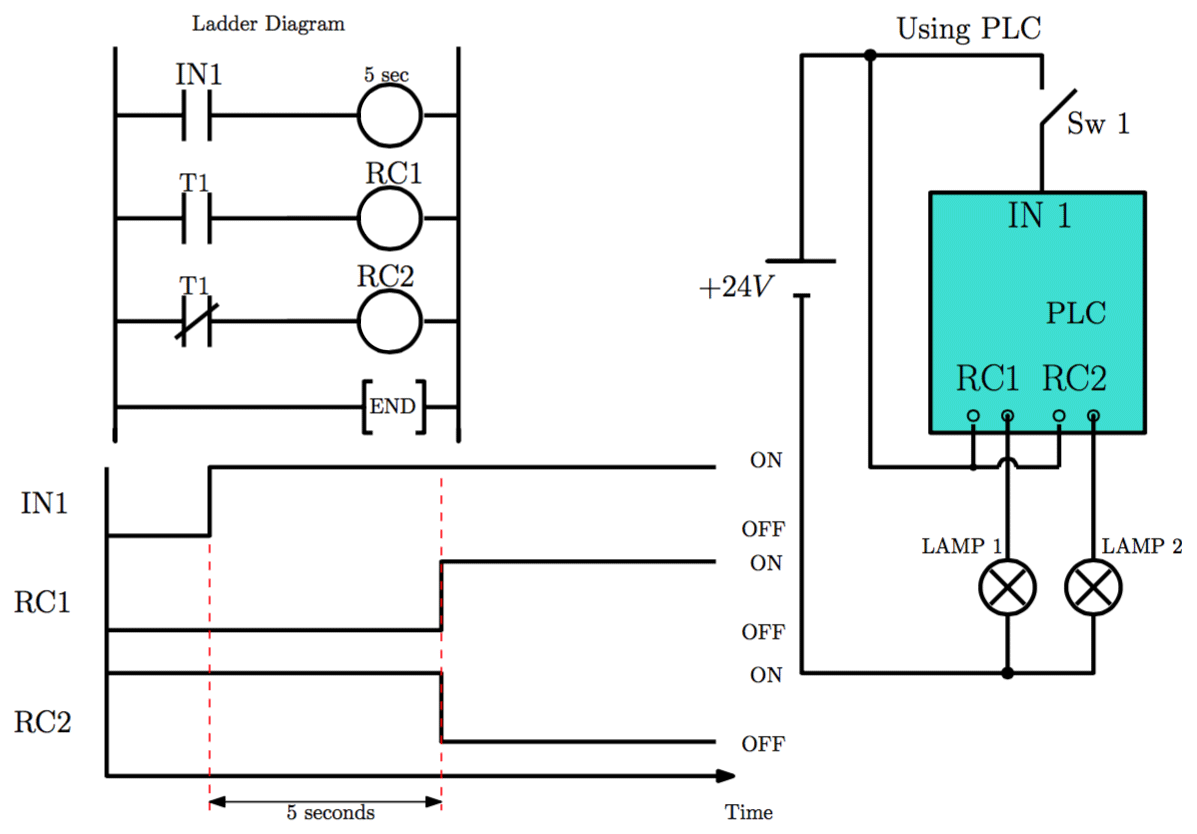
Figure: Using Timer in PLC
Example 11: Operating an Output for a Pre-set Time
- Figure shows how a PLC output can be turned ON for a pre-set time before being turned OFF.
- When the switch Sw 1 is closed, the timer T1 and the control relay RC1 are energised, turning the lamp ON. Five seconds later the timer contacts T1 open de-energising control relay RC1 turning OFF the lamp.
- [NOTE:] The contacts IN1 must be held closed to keep the timer energised during the delay period. Opening contacts IN1 reset the time delay back to the pre-set value and returns the contacts associated with the timer back to their de-energised state.
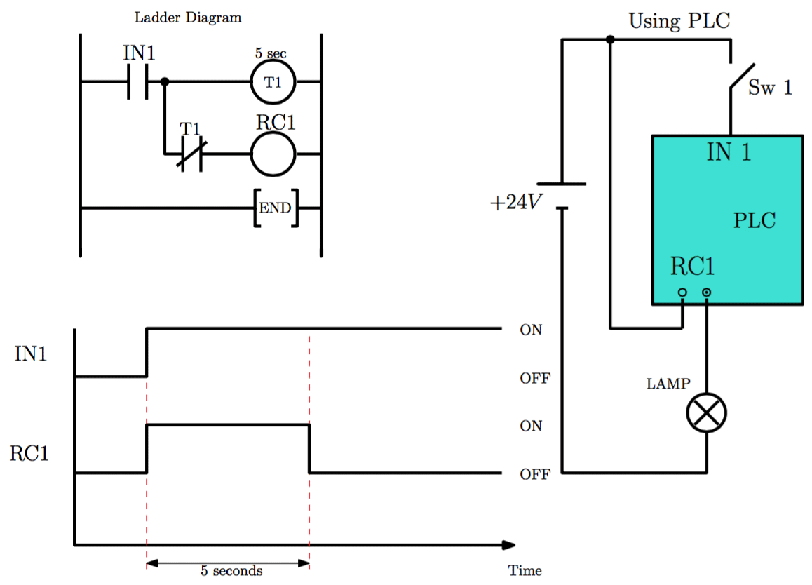
Figure: Using Timer in PLCExample 12: Sequencing outputs using timers
- The ladder diagram shows how to use 3 timers to repeatedly energise and de-energise control relays RC1, RC2 and RC3 one after the other as indicated in the timing diagram shown in the next slide.
- The sequencing starts when IN1 (push button with spring return) is momentarily pressed. This energise timer T1 and control relay RC1 for 5 seconds.
- When the 5 sec delay is completed, NC contacts of T1 is energised to open and control relay RC1 is de-energised. NO contacts of T1 closed to energise RC2 and T2.
- 5 seconds later NC contacts of T2 is opened and RC2 is de-energised and T2 resets itself. However NO contacts of T2 are closed to energise RC3 and start the timer T3. After 5 seconds T3 resets itself and start T1 again. External switch IN2 breaks all the latch circuit to stop the sequencing.

Figure: Sequencing with multiple timers
Example 12b: Timing diagram and the code for PLC

Example 3: Logical AND Function (Contacts in Series)
- 📷 Example 3: Figure shows an AND function.
Example 4: Logical OR Function (Contacts in Parallel)
- 📷 Example 4: Figure shows an OR function.
Example 5: Combined Logical AND and OR Functions (Contacts in Parallel & Series)
- 📷 Example 5: Figure shows an example which uses combinations of normally open contacts, normally closed contacts, AND and OR functions.
Example 6: Multiple Outputs
- 📷 Example 6: In this ladder programming, it is possible to connect more than one control relay to a contact.
Example 7: Coil Feedback
- 📷 Example 7: A control relay can be associated with a contact with the same label. When the control relay is energised, its associated contact changes state.
Example 8: Latch Circuit
- 📷 Example 8: A latch circuit is used to hold a control relay energised even if the input contact which energised it turned off. An example of a latch circuit is shown in this figure.
Example 9: Breaking the Latch Circuit
- 📷 Example 9: Figure here shows how to break a latch circuit. When the switch Sw1 is closed momentarily, contact IN1 closes momentarily and control relay RC1 is latched on.
- Why do we need them?