-


Programmable Logic Controllers (P.L.C's)
- Basics of Pneumatic and Hydraulic Systems, Controlled by a PLC
A great amount of pneumatic, hydraulic and electrical motor systems are used on a vast scale within automatic machines and plant and it is useful to understand the basic operation, symbols and control problems associated with electro-pneumatic, electro-hydraulic and electro-mechanical systems. An understanding of these systems enables us to create suitable ladder diagrams and programs for PLCs and so that to control these systems.
- Basics of Pneumatic and Hydraulic Systems, Controlled by a PLC
-
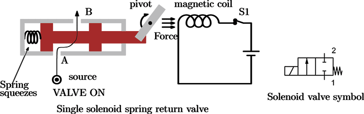
Figure: 2/2 Solenoid operated, spring return valve
A single solenoid and spring can also be used to switch a valve ON and OFF as shown in figure.The spring will always push the spool to the right keeping valve in the OFF position. Closing the switch energises solenoid S1 and pushes the spool to the left to squeeze the spring and turning the valve ON.When the solenoid is de-energised, the valve is turned OFF.The standard symbol used to represent 2/2 solenoid operated spring valve is shown in the right most figure.The use of 2/2 solenoid operated spring valve to operate a single acting cylinder is demonstrated in the video which can be seen in tab 8.8
Controlling pneumatic cylinders
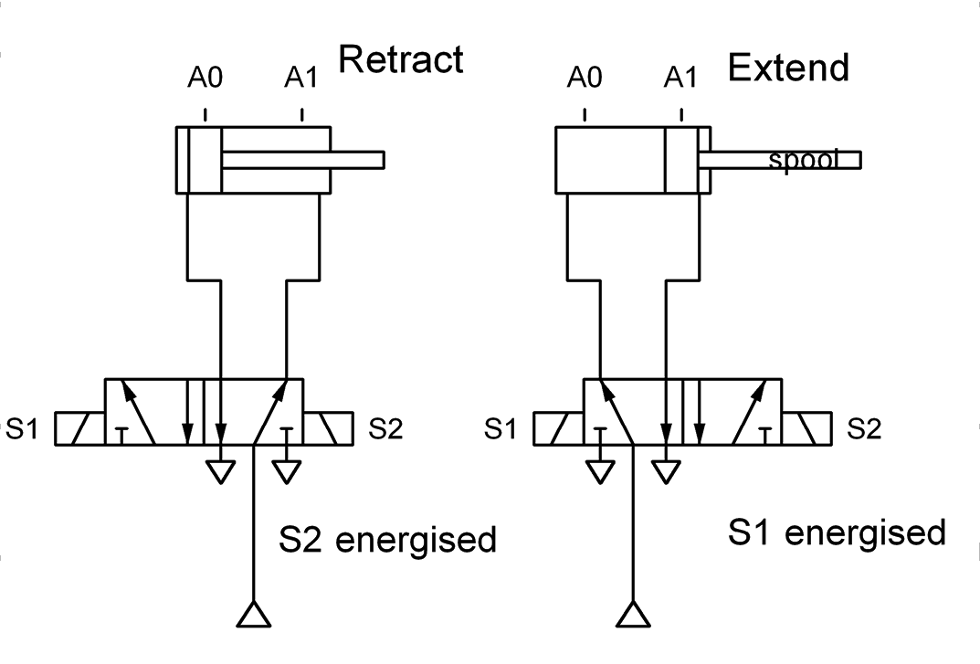
The most commonly used valve to control the extending and retracting of a pneumatic or hydraulic piston is to use 5 port, two position (5/2) solenoid operated, solenoid return valve.Energising the appropriate solenoids will extend or retract the piston. Referring to the figure, energising solenoid S1 will move the valve spool into a position which directs air forcing the piston to extend (A0 $\to$ A1).Similarly, energising solenoid S2 will move the valve spool into a position which directs air forcing the piston to retract (A1 $\to$ A0).NOTE: If both S1 and S2 are energised at the same time, the spool will not move, i.e. LOCKED signals. This is a common problem in PLC controlled systems. In the next section we shall discuss the ways of avoiding LOCKED signals in PLC programs.
Continues on next tab
Solenoid operated pneumatic, hydraulic and fluid ON/OFF valves
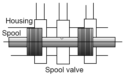
Figure: Valve
These valves have two main parts: the valve spool and the valve housing (case). Figure shows a typical valve spool and the its housing. The valve spool is dumbbell shaped with a narrow centre attached to larger ends. The valve housing (case) is cylindrical shaped and spool is an exact fit inside the housing.There are holes on the housing which are called the ports. These ports allow air or fluid to enter or exit the valve.The spool can slide from side to side inside the housing.
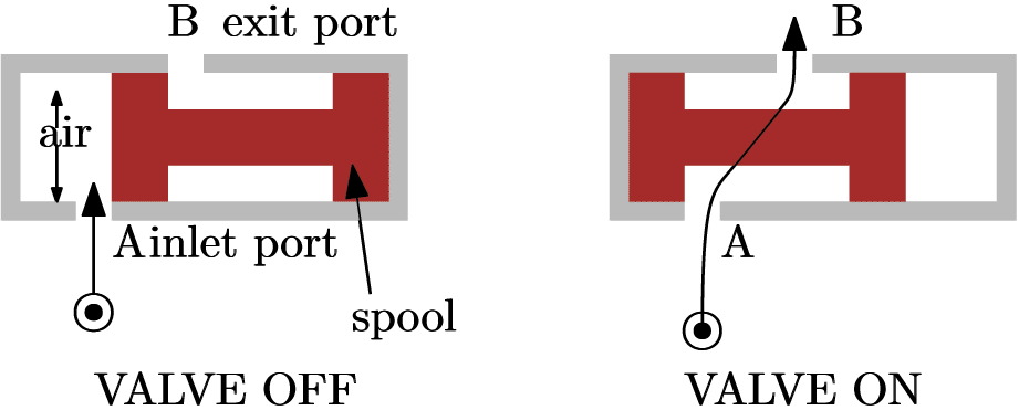
Figure: Operation of valve
The spool can slide from side to side inside the housing.The air/fluid can pass through the valve ports and exit the other side as shown in figure (right). This situation is called valve switched ON or moving the spool can stop fluid passing through the valve as shown in figure(left). This situation is called valve switched OFF.This valve is known as two port, two position (2/2) valve because the valve has 2 ports and the spool has two operating positions.In order to move or control the position of the spool, either pneumatic pilot valves or magnetic fields can be used. In the previous section we have seen how pneumatic pilot air can be used to control the spool. From now on, we shall discuss how the valves can be controlled by magnetic fields (solenoids).
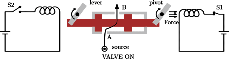
Figure: 2/2 Solenoid operated, solenoid return valve
Magnetic fields produced by solenoids can be used to move the valve spool as shown in the figure.Closing switch S1 will energise the associated serially connected coil pushing the spool to the left by the use of lever mechanism. This operation turns ON the valve since the air from the source can pass through A and B.Closing the switch S2 energises the left coil and pulls the top of left lever to the left pushing the spool to right. This operation turns OFF the valve.If both solenoids are energised at the same time, the magnetic fields oppose each other and the spool will not move. This is a condition known as blocked or locked signals.This valve is known as a 2 port, 2 position (2/2) solenoid operated, solenoid return valve..
-
Example 3: Extending, retracting a pneumatic piston using PLC timers
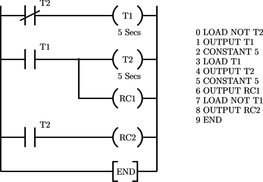
Figure: We use 2 timers T1 and T2 instead of latch circuits
The previous pneumatic control problem can be solved using a ladder diagram which uses timers instead of latch circuits, as shown in figure. This solution is based on the on the cylinder timer circuit discussed in the previous chapters.The 2 timers T1 and T2 set and reset each other at 5 seconds intervals with the result that RC1 and RC2 are toggled (i.e., switched so that RC1 is energised, RC2 is de-energised and vice versa) every 5 seconds.
Example 4: Automatic sequencing of 3 pistons using PLC’s
- Part 1 📷 Example 4: Automatic sequencing of 3 pistons using PLC’s
Part 2 (below) - Example 4: Automatic sequencing of 3 pistons
Figure: Ladder diagram
The task of the PLC is to extend then retract piston A, then piston B, then piston C using the arrangement shown in the figure given in the previous slide.This sequence A+, A-, B+, B-, C+, C- is continuously repeated when switch SW1 is closed.3 pneumatic pistons A,B and C are to be controlled using 5/2 solenoid operated, solenoid return valves.To achieve this sequence, the valve solenoids have to be energised in the following order S1, S2, S3, S4, S5, S6.Each solenoid has to be energised for a short period, at least long enough for the valve to switch the direction of the air.
Continues on next tabExamples of Engineering Systems Controlled by PLC’s
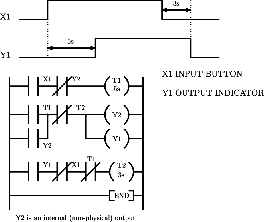
Figure: We want to obtain waveform Y1
which depends on the button input X1
as shown in the above figure.
Example 1: Timing
After 5 seconds the X1 button is pressed, the output indicator Y1 turns ON and 3seconds after the input X1 is released, Y1 turns OFF.We need 2 timers to count 5sec. and 3 sec of delays, namely T1 and T2Y2 is an internal relay which latches the current state of the output Y1.Rung 1 : 5sec timer starts counting as soon as X1 is pressed and Y1 (Y2) is OFF.Rung 2 : Whenever T1 reaches 5 seconds Y1 turns ON together with Y2 also NC contacts of T1 opens to reset timer T2.Rung 3 : When Y1 is ON, X1 is OFF and T1 is reset T2 starts counting for 3 seconds.Rung 2 : After 3 seconds the input X1 is released, T2 turns OFF its contacts switching the output Y1 OFF.
Example 2: Extending, retracting a pneumatic piston
- Part 1 📷 (this link) - Example 2: Extending, retracting a pneumatic piston
Part 2 (below) - Example 2: Extending, retracting a pneumatic piston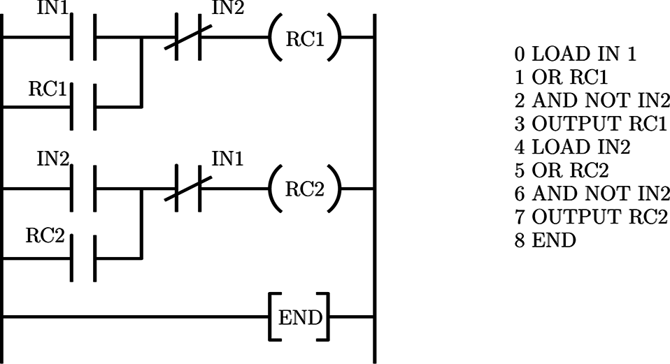
Figure: Rung 1 is used for A+, Rung 2 is used for A-
The ladder diagram for the control action is shown in figure. Two latch circuits (Rung 1 and Rung 2) are used.When contact IN1 is momentarily closed RC1 is energised via the latch circuitWhen IN2 is momentarily closed, RC1 is de-energised (IN2 resets the latch) and RC2 is energised via second latch circuit.Second latch circuit is reset when IN1 contacts close. This avoids LOCKED signals.
2 Sets of Reading obtained by 2 different measurement devices of the same quality Instrument 1 20.1mm 20.2mm 20.0mm 20.1mm 20.1mm 20.1mm 20.0mm Instrument 2 19.9mm 20.3mm 20.0mm 20.5mm 20.2mm 19.8mm 20.3mm
Example 2: Extending, retracting a pneumatic piston
- Task
The task of the PLC is to move the piston in and out of the double acting cylinder shown in the arrangement in the next slide. When Sw1 is momentarily closed piston A will extend out of the cylinder (A+). When switch Sw2 is momentarily closed piston A is to retract into the cylinder (A-).- System description
Interfacing the 24 volts solenoids to the relay output port is straightforward. The input switches can either be activated manually by the user or the piston itself. In the latter case, either switches can be mounted externally so that they are activated by the piston at either end of its stroke or, provided the piston is magnetic, Reed switches at the end of the cylinder may be used.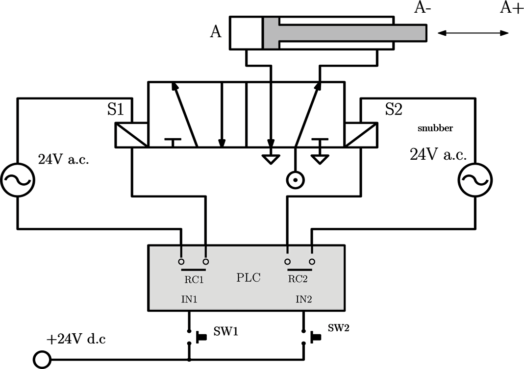 Figure: PLC interconnection
Example 4: Automatic sequencing of 3 pistons using PLC’s
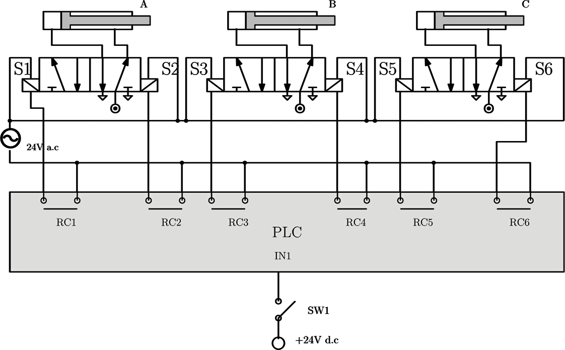 Figure: PLC interconnection for controlling 3 pistons sequentially (A+,A-,B+,B-,C+,C-, continuously repeated)
-
Example 6: Tea Maker
- Part 1 📷 (this link) - Example 6: Tea Maker
- Part 2 - Example 6: (below) Tea Maker
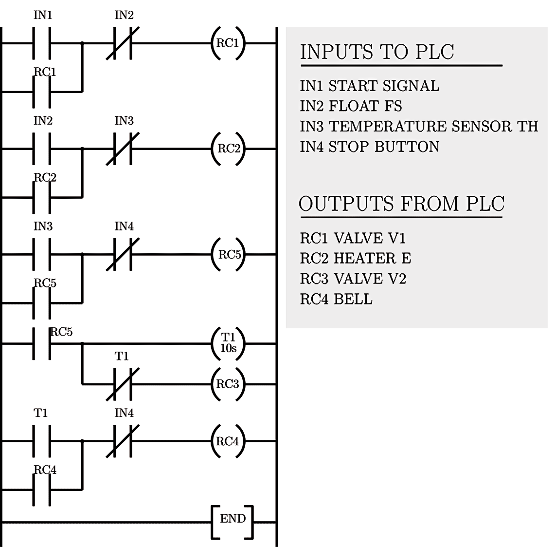
NOTE: RC5 is known as a dummy output. This output is not connected to any actuators on the process. It is only used on other rungs in the ladder diagram.NOTE: Dummy output also called an auxiliary output.Example 5: Automatic sequencing of 3 pistons using PLC’s (using limit switches)
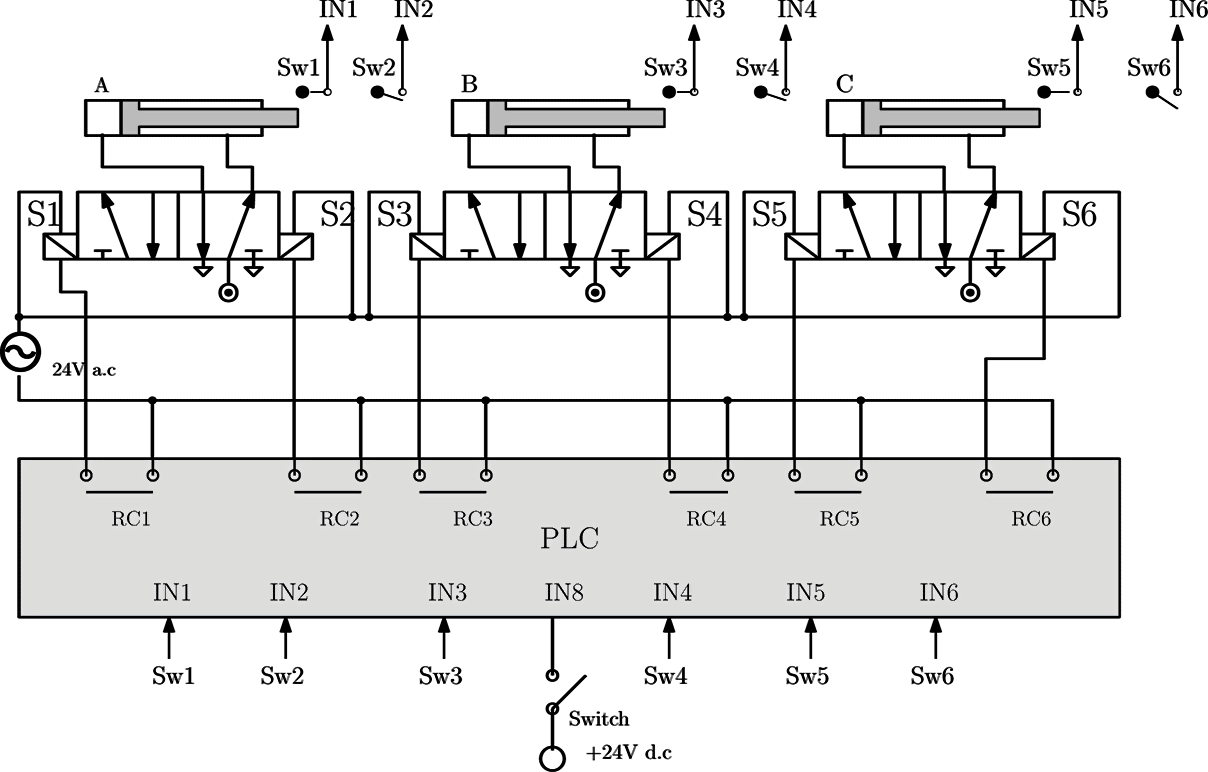
Figure: PLC interconnection for controlling 3 pistons sequentiallyExample 6: Tea Maker (part 1)
- Figure shows a system for making a pot of tea. Water tank (T) contains cold water. Water flows from this tank through valve V1 into the kettle K
- The float switch FS detects when the kettle is full. The heating element E heats the water to boiling point as detected by the temperature sensor TH.
- When the water is at boiling point valve V2 opens to pour water into the teapot. There is no float switch to detect when the teapot is full, instead valve V2 is opened for 10 seconds then closed, this fills the teapot with enough water.
- A bell then rings to indicate the process is completed. The bell is manually turned off by a spring return push button switch.
- When the float switch or thermostat is activated a +24 volt signal is sent to PLC.
- The process is started by an external presentable timer which sends a short pulse to the PLC every 24 hours.

- The temperature transmitter senses the temperature of the lube oil as it leaves the cooler and sends an air signal that is proportional to the temperature controller. Next, the temperature controller compares the actual temperature of the lube oil to the setpoint (the desired value).
If a difference exists between the actual and desired temperatures, the controller will vary the control air signal to the temperature control valve. This causes it to move in the direction and by the amount needed to correct the difference. For example, if the actual temperature is greater than the setpoint value, the controller will vary the control air signal and cause the valve to move in the open direction.
- (B) represents the lube oil temperature control loop in block diagram form. The lube oil cooler is the plant in this example, and its controlled output is the lube oil temperature. The temperature transmitter is the feedback element. It senses the controlled output and lube oil temperature and produces the feedback signal.
The feedback signal is sent to the summing point to be algebraically added to the reference input (the setpoint). Notice the setpoint signal is positive, and the feedback signal is negative. This means the resulting actuating signal is the difference between the setpoint and feedback signals.
The actuating signal passes through the two control elements: the temperature controller and the temperature control valve. The temperature control valve responds by adjusting the manipulated variable (the cooling water flow rate). The lube oil temperature changes in response to the different water flow rate, and the control loop is complete.
Example 5: Automatic sequencing of 3 pistons using PLC's (using limit switches)
- Part 1 📷 (this link) - Example 5: Figure: PLC interconnection for controlling 3 pistons sequentially
Part 2 - Example 5: (below) Automatic sequencing of 3 pistons using limit switches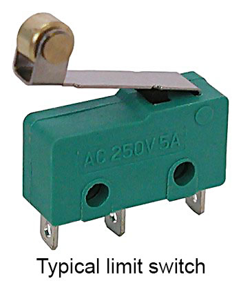
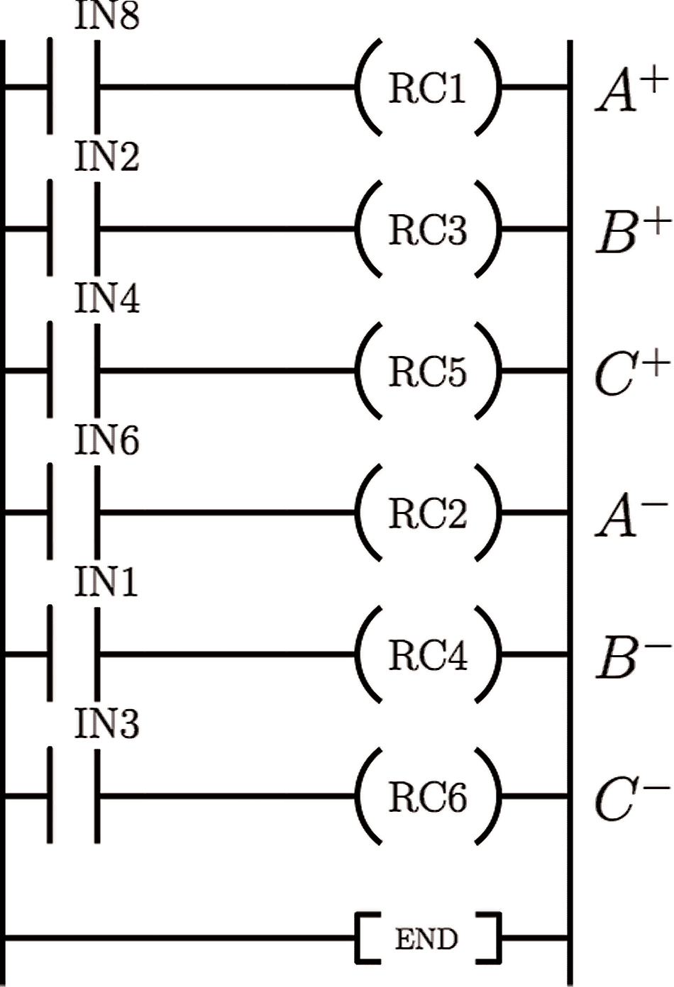
Limit switches (Sw$i$, $i=1,\ldots, 6$) can be positioned at each end of the pistons stroke (A+ and A- positions etc.)These switches (please look at the figure on the left) are normally open spring metal micro switches. The piston rod forces these switch contacts closed, when they are not in contact with the piston rod, they spring open.+24V signal from these switches are connected to the PLC inputs. The PLC therefore definitely knows if a piston is extended or retracted. Hence, the system is much safer than relying on timers.In the previous example, one cylinder could get stuck but the other pistons would continue to cycle, which could be unsafe or cause further damage to the machine or process.NOTE: The start switch (connected to IN8) will only needed to be closed momentarily, then opened again to achieve one cycle of the above cylinders. Otherwise, cylinders would lock in the A+, B+, C+ position.
-
Example 8: Automatic door
- Part 1 📷 Example 8: Automatic door
- Part 2 - Example 8: Automatic door (Ladder diagram)

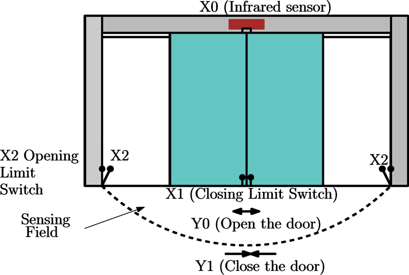
X0 = ON if someone enters the sensing field of the infrared sensor. Y0 will be ON and latched, and the door will be opened as long as the opening limit switches X2 = OFF.When the door touches the opening limit switches, X2 = ON. The timer T0 will start to count for 7 sec if no one enters the sensing field (X0 = OFF). After 7 sec., Y1 will be ON and latched and the door will be closed.During the closing process, X0 = ON if someone enters the sensing field. The NC contact X0 will be activated to turn Y1 off. Because X0 = ON, X2 = OFF and Y1 = OFF, Y0 will be ON and the door will be opened once again.
Example 7: Liquid Mixer
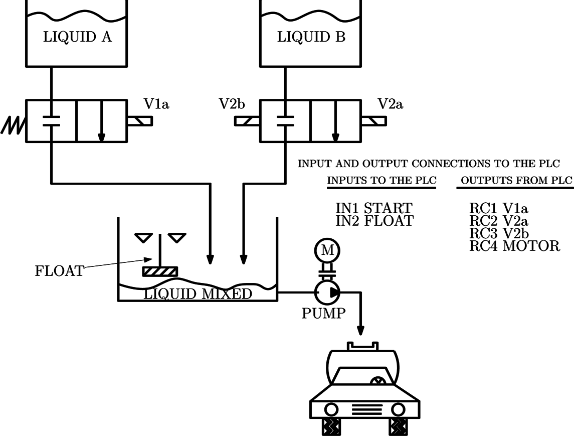
- Figure shows a process where two liquids A and B are mixed together. The mixture is then pumped into the tanker for delivery.
- The process is to be controlled as follows:
- V1 and V2 operate (simultaneously) until mixing vessel is full as detected by the float switch.
- V1 and V2 switch off
- Liquid is pumped to the tanker (it takes 20 minutes to fill the tanker)
Example 7: Liquid Mixer
- Part 1 📷 Example 7: Liquid Mixer
- Part 2 - Example 7: Liquid Mixer, Ladder diagram
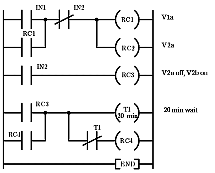
Rung 1: Start (IN1) latches on V1 and V2aRung 2: Float (IN2) energises V2b (RC3) and breaks latch on Rung 1Rung 3: RC3 energises timer and Motor (M) (RC4) for 20 minutes
Example 8: Automatic door
- When someone enters the infrared sensing field, opening motor starts working to open the door automatically till the door touches the opening limit switch
- If the door touches the opening limit switch for 7 sec and nobody enters the sensing field, the closing motor starts working to close the door automatically till the closing limit switch touched together.
- Stop the closing action immediately if someone enters the sensing field during the door closing process.
-
(Cont.)
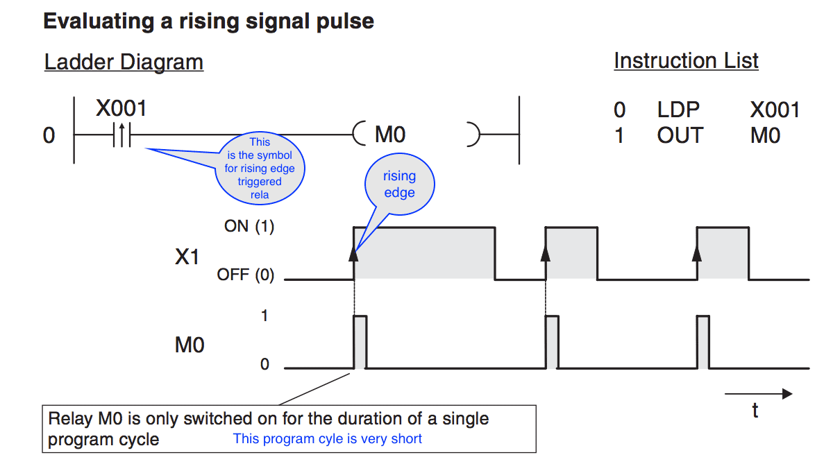
- During program execution operations that respond to rising and falling pulses only deliver a value of “1” when the signal state of the referenced device changes.
- When do we need this?
Suppose you have a conveyor belt with a sensor switch that activates to increment a counter every time a package passes it on the belt. If you don’t use a pulse-triggered function you will get incorrect results because the counter will increment by 1 in every program cycle in which the switch registers as set. If you only register the rising pulse of the switch signal the counter will be incremented correctly, increasing by 1 for each package.
- Pulse-triggered execution of operations:
Timers in Mitsubishi PLCs
- Types of timers
When you are controlling processes you will often want to program a specific delay before starting and stopping certain operations. In PLCs this is achieved with programmable internal timers.There are 2 kinds of timers in Mitsubishi PLCs. These are Normal (Ordinary) Timers and Retentive Timers.Timers are really just counters that count the PLCs internal clock signals (e.g. 0.1s pulses). When the counter value reaches the setpoint value the timer’s output is switched on.All timers function as make delay switches and are activated with a “1” signal. To start and reset timers you program them in the same way as outputs. You can poll the outputs of timers as often as you like in your program.Normal Timers
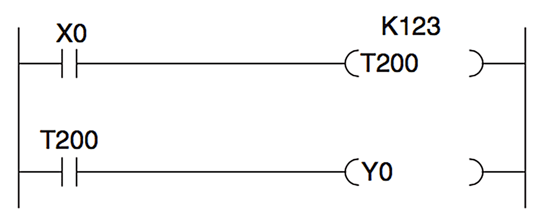 In the above example timer T200 is started when input X0 is switched on. The setpoint value is $123 \times 10\mathrm{ms} = 1.23 \mathrm s$, so T200 switches on output Y0 after a delay of $1.23 \mathrm s$. The signal sequence generated by the following program example is as follows:
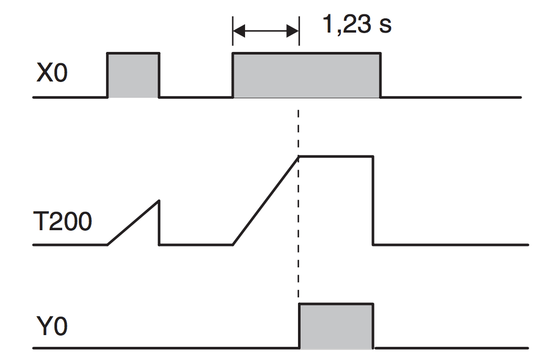 The timer continues to count the internal $10\mathrm{ms}$ pulses as long as X0 remains on. When the setpoint value is reached the output of T200 is switched on.If input X0 or the power supply of the PLC are switched off the timer is reset and its output is also switched off.
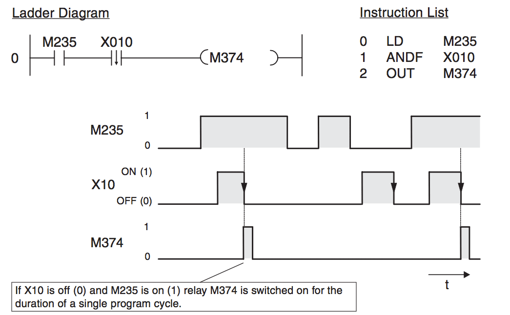
Device name Type Function X Input Input terminal on the PLC (e.g. for a contactor or lamp Y Output Output terminal on the PLC (e.g. connected to a switch M Relay A buffer memory in the PLC that can have two steps: ON and OFF T Timer A "time relay" that can be used to program timed functions C Counter A counter D Data register Data storage in the PLC in whichyou can store things like measured values and the results of calculations
Advanced Topics in PLC
- The content of the section
So far we have seen fundamental components -such as NC, NO contacts, relays, timers - that are used in almost every PLC that is used in industry.We have also used a generic method to demonstrate the usage of these elements without considering specific PLC brands. Note that every PLC brand has its own ladder diagram structure and components. The rule of thumb is that as the price of the PLC increases, the capability, I/O ports, number of timers, counters and the number of commands all increase.In the lab sessions of this module, we use Mitsubishi PLCs. Therefore we shall continue with Mitsubishi-specific commands.
Mitsubishi PLCs: Code Structure
Code structure
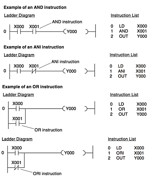
1. A program instruction consists of the instruction itself (sometimes referred to as a command) and one or more (in the case of applied instructions) operands, which in a PLC are references to devices.2. The illustrations below show how program instructions are represented in the Ladder Diagram (LD, left) and Instruction List (IL, right) programming language formats:

- 📷 Examples of devices
Commonly codes used in Mitsubishi PLCs
Pulse-triggered execution of operations
- In PLC programs you will often need to detect and respond to the rising or falling edge of a bit device’s switching signal. A rising edge indicates a switch of the device value from “0” to “1”, a falling edge indicates a switch from “1” to “0”.
-
Counters in Mitsubishi PLCs
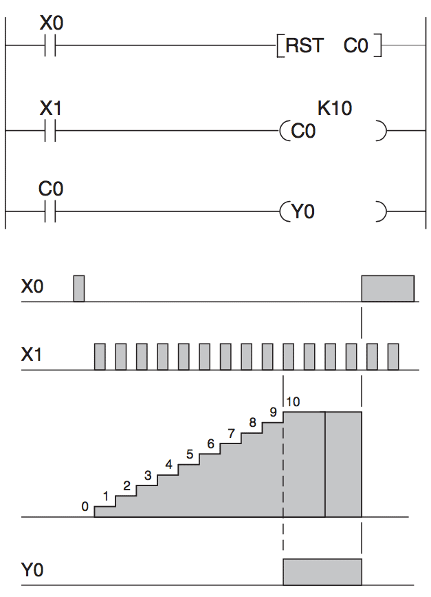
FX family also have internal counters that you can use for programming counting operations.Counters count signal pulses that are applied to their inputs by the program. The counter output is switched on when the current counter value reaches the setpoint value defined by the program.Consider the example on the left. When X0 is switched on Counter C0 is reset. and on the each rising edge of X1, the value of the counter is increased by one until the value reaches to the setpoint KXX (in our example it is 10).As soon as the setpoint vale is reached the output Y0 is activated by the counter output relay C0.Once the counter value has reached the setpoint value any additional pulses on input X1 no longer have any effect on the counter.Timers in Mitsubishi PLCs (Cont.)
- Retentive Timers
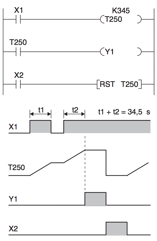
In addition to the normal timers, described in the previous tab, Mitsubishi PLCs also have retentive timers that retain their current time counter value even if the device controlling them is switched off.
The current timer counter value is stored in a memory that is retained even in the event of a power failure.Timer T250 is started when input X0 is switched on. The setpoint value is 345 x 0.1 s = 34.5s. When the setpoint value is reached T250 switches output Y1 on. Input X2 resets the timer and switches its output off.When X1 is on the timer counts the internal 100ms pulses. When X1 is switched off the current time counter value is retained. The timer’s output is switched on when the current value reaches the setpoint value of the timer.
NOTE: In FX1N, FX2N and FX3U series PLCs, Timers T0 to T199 are 100ms step size normal timers whereas T250 to T255 are of retentive type.
- We shall start with the design of a proportional controller (P) for the system having a transfer function $ G(s)=\large\frac{1}{s^3+3s^2+3s+1} $ where $s$ is the Laplace variable which stands for the time-derivative operation $d/dt$. According to this transfer function, the associated simulation screen should look like the following
 Here $\tau_I$ is the integral time constant $T_i$, $\tau_D$ is the derivative time constant $T_d$ and $K_C$ is the control gain $K$. Finally $\alpha$ stands for the derivative filter constant which needs to be tuned during the design.
- Following the Ziegler-Nichols technique, the critical gain is found to be $K_C=7.83$ by setting $T_i=10000$, $T_d=0$. Hence, for the proportional control the control gain is found to be $K=3.91$ which gives the following system response. It is clear that the performance of the proportional control is very poor. The response is oscillatory and there is $25\%$ steady-state error, (set point=$1$, steady-state response=$0.75$)

- Following the Ziegler-Nichols technique, the critical gain is found to be $K_C=7.83$ and the critical period, $T_C=3.7s$. Hence, for the proportional+integral control, the control gain and the integral constant are found to be as $K=3.13$ and $T_i=0.83\times 3.7=3.07 $ which give the following system response. It is clear that the performance of the PI control is very similar to the proportional controller but there is no steady-state error.

- Following the Ziegler-Nichols technique, the critical gain is found to be $K_C=7.83$ and the critical period, $T_C=3.7s$. Hence, for the proportional+integral control, the control gain, the integral constant and derivative constant are found to be as $K=4.7$ and $T_i=0.5\times 3.7=1.85$ and $T_d=0.125\times 3.7=0.46$ which give the following system response. It is clear that the performance of the PID control is much better than the PI and P controllers.

- Retentive Timers
-
Example of usage of CMP instruction
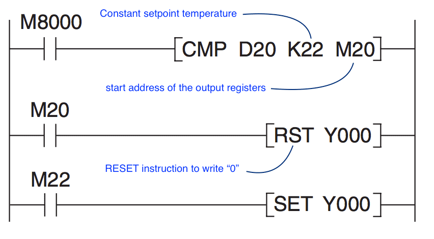
Fan Control
In this example the CMP instruction is executed cyclically. M8000 is always “1” when the PLC is executing the program. Register D20 contains the value for the current room temperature. Constant K22 contains the setpoint value of $22^\circ \mathrm C$. Relays M20 and M22 show when the temperature goes higher or lower than the setpoint. If the room is too warm output Y0 is switched off. If the temperature is too low M22 switches output Y0 on again. This output could be used to control a pump for adding hot water, for example.- 📷 Fan Control Diagram
Comparison with Logic Operations:
($>$, $<$, $=$, $\ge$, $\le$, $\neq$)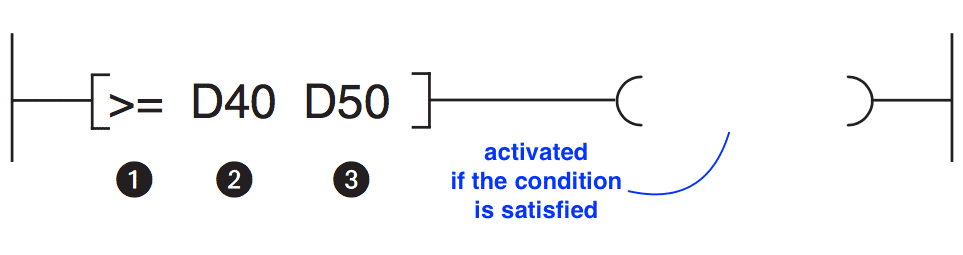
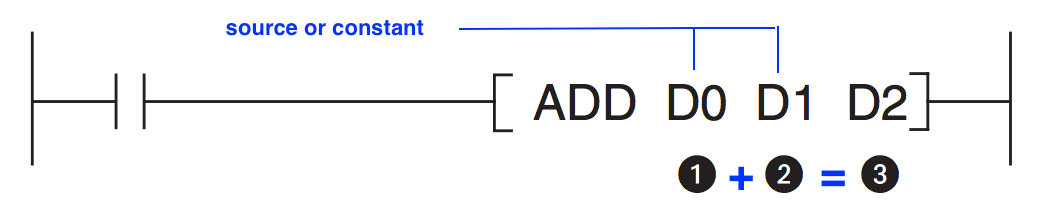
- ❶ Compare Condition
- ❷ First compare value
- ❸ Second compare value >=, <=, >, <, =, <>
If the condition evaluates true the signal state after the comparison is set to “1”. A signal state of “0” shows that the comparison evaluated as false. The following comparisons are possible:$\large =$ The output of the instruction is only set to "1" if (value 1 $\large=$ value 2)$\large>$ The output of the instruction is only set to "1" if (value 1 $\large>$ value 2)$\large<$ The output of the instruction is only set to "1" if (value 1 $\large<$ value 2)$\large>=$ The output of the instruction is only set to "1" if (value 1 $\large\ge$ value 2)$\large<=$ The output of the instruction is only set to "1" if (value 1 $\large\le$ value 2)$\large<>$ The output of the instruction is only set to "1" if (value 1 $\large\neq$ value 2)MATH Operations
For example, assume you are using a counter to keep track of the number of parts manufactured, and you would like to display how many more parts must be produced in order to reach a certain quota. This display would require the data in the accumu- lated value of the counter to be subtracted from the quota re- quired. Other applications include combining parts counted, subtracting detected defects, and calculating run rates.All the controllers of the Mitsubishi FX family can perform all four basic arithmetical operations and can add, subtract, multiply and divide integer numbers (i.e. non-floating-point numbers). These instructions are described in this section.The controller base units of the FX2N, FX2NC and FX3U series can also process floating-point numbers. This is done with special instructions but we shall not cover those instructions in this course and stick to operations of integer numbers.It is very likely that these mathematical operations can produce numbers which might fall out of the 16 bits or 32 bits range, known as overflow, therefore after every addition or subtraction you should always program instructions to check the states of the special relays listed below to see whether the result is $0$ or has exceeded the permitted value range.Special Registers devoted to Math Operations
- M8020
This special relay is set to "1" if the result of an addition or subtraction is 0- M8021
Special relay M8021 is set to "1" if the result of an addition or subtraction is smaller than $-32,767$ ($16$-bit operations) or $-2,147,483,648$ ($32$-bit operations).- M8022
Special relay M8022 is set to "1" if the result of an addition or subtraction is greater than $+32,767$ (16-bit operations) or $+2,147,483,647$ (32-bit operations).Registers
The PLC’s relays are used to store the results of operations temporarily. However, relays can only store values of On/Off or 1/0, which means that they are not suitable for storing measurements or the results of calculations. Values like this can be stored in the registers of the controllers of the FX family.Registers are 16 bits or one word wide. You can create double word registers capable of storing 32-bit values by combining two consecutive data registers.A normal 16-bits register can store values in between (-32,768 – 32,767), whereas an 32 bits register can store values in between (-2,147,483,648 – 2,147,483,647)Data registers can be used as memory in your PLC programs. A value that the program writes to a data register remains stored there until the program overwrites it with another value.
Moving data between Registers
When you use instructions for manipulating 32-bit data you only need to specify the address of a 16-bit register. The more significant part of the 32-bit data is automatically written to the next consecutive register. For example, if you specify register D0 to store a 32-bit value D0 will contain bits 0 through 15 and D1 will contain bits 16 through 31.
The PLC uses data registers for storing measurements, output values, intermediate results of operations and table values. The controller’s math instructions can read their operands directly from the data registers and can also write their results back to the registers if you want. However, these instructions are also supported by additional “move" instructions, with which you can copy data from one register to another and write constant values to data registers.
Move instruction
- 📷 Move instruction diagram
Compare instructions: CMP
- Checking the status of bit devices like inputs and relays can be achieved with basic logic instructions because these devices can only have two states, “0” and “1”. However, you will also often want to check the contents of word devices before doing something – for example switching on a cooling fan when a specified setpoint temperature is exceeded. The controllers of the MELSEC FX family provide a number of different ways to compare data.
In the below example the CMP instruction controls relays M0, M1 and M2. M0 is “1” if the contents of D0 is greater than 100; M1 is “1” if the contents of D0 is precisely 100 and M2 is “1” if D0 is less than 100. The state of the three bit devices is maintained even after the input condition has been switched off because their last state is stored.
- ❶ Input Condition
- ❷ First value to be compared
- ❸ Second value to be compared
- ❹ First of three consecutive relays or outputs, which are set (signal status “1”) depending on the result of the comparison:
Device 1: ON if Value 1 $>$ Value 2Device 2: ON if Value 1 $=$ Value 2ON if Value 1 $<$ Value 2
- We shall start with the design of a proportional controller (P) for the system having a transfer function $ G(s)=\large\frac{1}{s^3+3s^2+3s+1} $ where $s$ is the Laplace variable which stands for the time-derivative operation $d/dt$. According to this transfer function, the associated simulation screen should look like the following
Here $\tau_I$ is the integral time constant $T_i$, $\tau_D$ is the derivative time constant $T_d$ and $K_C$ is the control gain $K$. Finally $\alpha$ stands for the derivative filter constant which needs to be tuned during the design.Move instruction
- Following the Ziegler-Nichols technique, the critical gain is found to be $K_C=7.83$ and the critical period, $T_C=3.7s$. Hence, for the proportional+integral control, the control gain and the integral constant are found to be as $K=3.13$ and $T_i=0.83\times 3.7=3.07 $ which give the following system response. It is clear that the performance of the PI control is very similar to the proportional controller but there is no steady-state error.
- Following the Ziegler-Nichols technique, the critical gain is found to be $K_C=7.83$ and the critical period, $T_C=3.7s$. Hence, for the proportional+integral control, the control gain, the integral constant and derivative constant are found to be as $K=4.7$ and $T_i=0.5\times 3.7=1.85$ and $T_d=0.125\times 3.7=0.46$ which give the following system response. It is clear that the performance of the PID control is much better than the PI and P controllers.
-
Solenoid Valves Video
Example: Using special registers in Math operations
These special relays can be used as enable flags for continuing with additional math operations. In the following example the result of the subtraction operation in D2 is used as a divisor. Since dividing by 0 is impossible and causes an error the division is only executed if the divisor is not 0.In this example, when M8000 relay is activated, content of register D1 is subtracted from D0 and the result is recorded into D2. Then, when M8020 is not activated, in other words if the previous subtraction does not produce a $0$ result, D3 $\div$ D2 is performed and the result is transferred to D5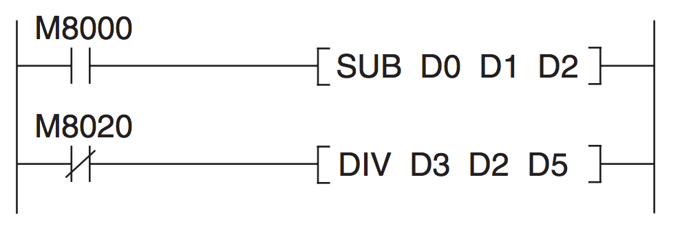
Math Operations:
- 📷 Math operation: Addition
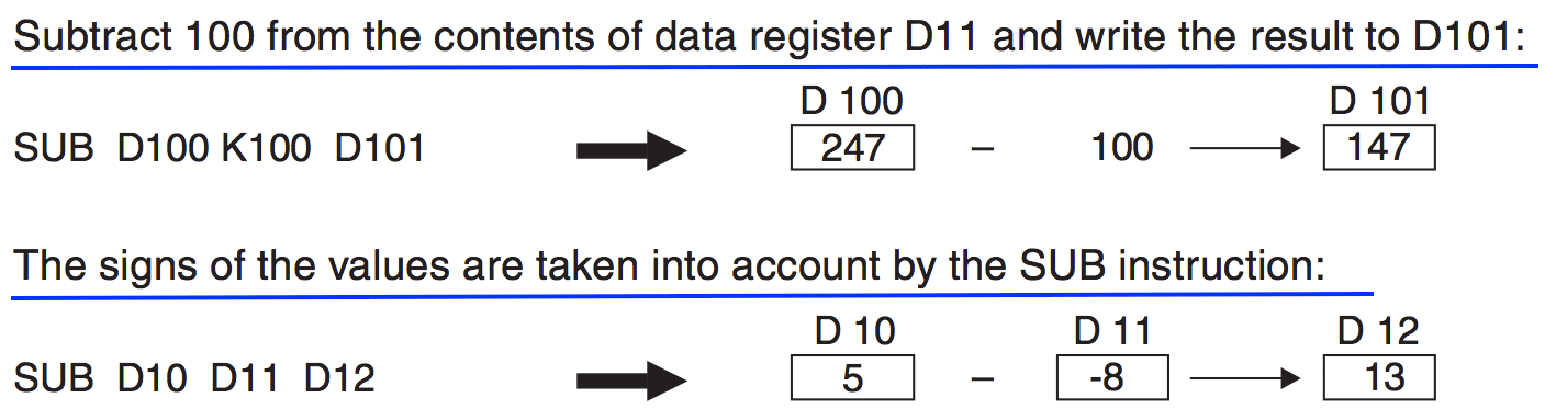
- 📷 Math operation: Subtraction
- 📷 Math operation: Multiplication
- 📷 Math operation: Division
Example: Speed Trap
- You are asked to design a speed trap which calculates the speed of the vehicle in between two points A and B where two photocell sensors PC1 and PC2 are mounted, respectively. The distance between points A and B is 200 meters. The speed of the vehicle is calculated using the time that it takes for the vehicle to go from PC1 to PC2.
- The distance between point A and point B is to be recorded into the data register D12 (in meters). The operator has the choice to check the vehicle speed or not and this is achieved by pressing the push button giving input X004.
- When the operator activates the input X004, the speed of the vehicle is needed to be calculated and the final speed needs to be stored in data register D20 (in km/h).
The detectors PC1 and PC2 can be used to start and stop the timer which records the time elapsed for the vehicle in between point A and B. You can use T200 for this keeping in mind that T200 is a 10ms timer. Which means that for example, if we have T2=$213$ then the exact time calculated by the timer=$213 \times 10 = 2130\mathrm{ms}$.
- 📷 Speed Trap (Cont.)
- 📷 Speed Trap (Cont.)
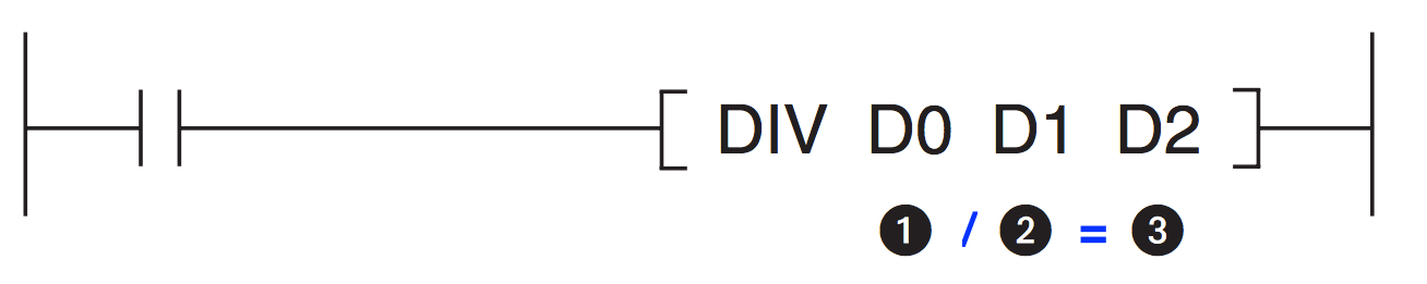
Math operation: Division

Math operation: Addition
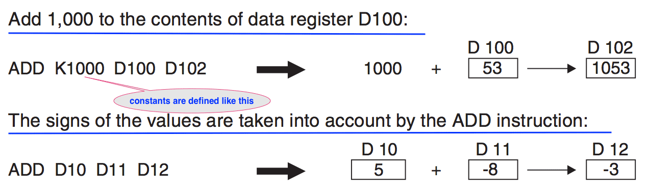
Math operation: Subtraction

Math operation: Multiplication


Speed Trap (cont.)
Device PLC Device Description PC1 X000 Start Timing PC2 X001 Stop Timing Button X004 Calculate Speed Input T200 A 10ms timer D010 Elapsed time for travel between PC1 and PC2 D012 Distance between PC1 and PC2 PC1 D020 The speed of the vehicle between PC1 and PC2

Speed Trap (cont.)
