-
Design of Pneumatic Systems
- Introduction
A pneumatic system is a system that uses compressed air to transmit and control energy. Pneumatic systems are used in controlling train doors, automatic production lines, mechanical clamps, etc. Pneumatic control systems can be designed in the form of pneumatic circuits. A pneumatic circuit is formed by various pneumatic components, such as cylinders, directional control valves, flow control valves, etc. Pneumatic circuits have the following functions:
1. To control the injection and release of compressed air in the cylinders.
2. To use one valve to control another valve. In this unit, we shall discuss the equipment that is used in pneumatic systems. We are going to start with learning about directional control valves and cylinders together with their usage in real applications. Finally, we shall discuss how to design complex sequential pneumatic circuits which perform complex tasks.
- Introduction
-
Single-acting cylinder working principle
- If we stop the supply of air then the spring inside the cylinder causes the piston to instroke to its starting position and the piston is said to be negative . As this happens, the air inside the cylinder is pushed back out.
 Single-acting cylinders are easy to use and control but they do not produce very big forces. This means that we need to be careful of what we use them for.
 Double-acting cylinder
- A double-acting cylinder has no spring inside to return it to its original position. It needs two air supplies, one to outstroke the piston and the other to instroke the piston. To outstroke a double-acting cylinder we need compressed air to push against the piston inside the cylinder. As this happens, any air on the other side of the piston is forced out. This causes the double-acting cylinder to outstroke. When the piston has fully outstroked it is said to be positive.
To instroke a double-acting cylinder we need to reverse this action. We supply the compressed air to the other side of the piston. As the air pushes the piston back to its original position, any air on the other side is again forced out. This causes the piston to instroke and it is said to be negative.
Directional Control Valves and Cylinders
Pneumatic and hydraulic systems use directional control valves to direct the flow of fluid through a system; They are ON/OFF devices either completely open or closed.They might be activated to switch the fluid flow direction by means of mechanical, electrical or fluid pressure signal.
- Pneumatic equipment
Pneumatic equipment can be split up into two basic categories of cylinders and valves.
Cylinders are the ‘muscles’ of pneumatic systems as they are used to move, hold and lift objects. They can even be used to operate other pneumatic components. Cylinders are operated by compressed air and they covert the stored energy in the compressed air into linear motion.
Pneumatic Cylinders
- types of pneumatic cylinders
There are two types of cylinder that we will be using: single-acting cylinders and double-acting cylinders.- Single-acting cylinder
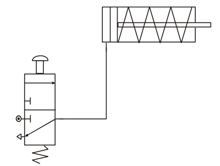
A single-acting cylinder requires only one air supply. If we supply compressed air to a single-acting cylinder, the air pushes against the piston inside the cylinder and causes it to outstroke. When the piston has fully outstroked it is said to be positive.

- If we stop the supply of air then the spring inside the cylinder causes the piston to instroke to its starting position and the piston is said to be negative . As this happens, the air inside the cylinder is pushed back out.
-
Example
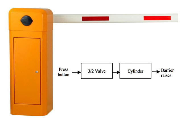
- A park barrier system is to prevent people parking illegally. The car park attendant checks all the cars entering and leaving the car park. The barrier is raised and lowered by a single-acting cylinder. The attendant pushes a button to operate the system.
- When the button is pressed, the valve changes state and supplies air to the single-acting cylinder. This causes the piston to outstroke with enough force to raise the barrier.
When the button is released, the valve returns to its original state and the piston is able to instroke ready for the process to begin again.Example: Brake System
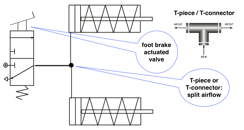
- A delivery lorry uses a pneumatic braking system. The brakes operate when the driver presses the foot brake. Two single-acting cylinders should outstroke at the same time and press against the wheels. The pneumatic circuit is shown below.
Valves
- Valves control the flow of compressed air to a cylinder. They can be used to turn the air on or off, change the direction in which the air is flowing or even slow down the airflow. The most common type of valve is the 3/2 valve.
- 3/2 Valve
A 3/2 valve gets its name because it has three ports and two states. A port is where we can connect a pipe and a state is simply a position that the valve can be in. The ports are numbered to help us make the right connections. The numbers will be stamped onto the casing of the valve.
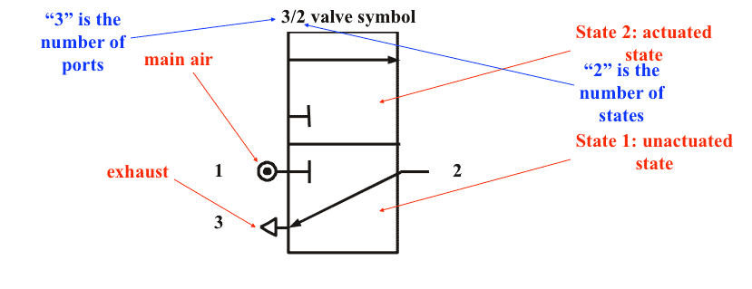
- Port 1 - Main air
This port is connected to main air. Remember that our main air is supplied through a manifold and produced by a compressor. Main air is identified by the symbol shown in the figure.- Port 2 - Output connection
This port lets us make connections to other components. Remember, the purpose of valves is to control the flow of air to other components, usually cylinders.- Port 3 - Exhaust
This port allows air trapped in the circuit to escape or exhaust. Remember, for our cylinders to instroke and outstroke, they need the air on the other side of the piston to escape.Valves States
- State 1 - off/unactuated state
In this state, the main air supply through the valve is blocked and so air is unable to reach other components, such as cylinders. However, any air within the cylinder is able to exhaust through the valve and this will allow the cylinder to return to its original position.- States 2 - on/actuated state
In this state, the main air supply is able to flow freely through the valve and supply components, such as cylinders, with air.Valve actuators

-
(Cont.)A further disadvantage is that the 3/2 valve needs to be actuated until the double- acting cylinder has fully outstroked or instroked. Releasing the valve before the stroke is complete will mean the piston will stop short of its final position.We have greater control over a double-acting cylinder if we control its outstroke and instroke using a 5/2 valve. This valve has five ports and two states of operation. The ports are always numbered in the same way.

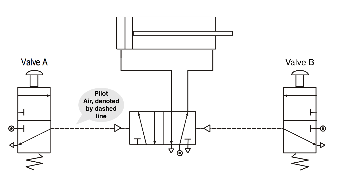
5/2 Valves with pilot air
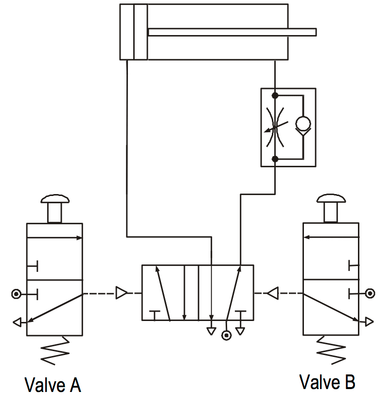
- 5/2 valves can be operated or actuated in the same way as 3/2 valves. However, the most common way of actuating a 5/2 valve is by pilot air. A pilot air 5/2 valve will change state when a brief air signal acts at either end of the valve. This signal is most often supplied from a 3/2 valve. In the example shown below, the button on valve A only needs to be pressed for a moment in order to change the state of the 5/2 valve. The 5/2 valve supplies the double-acting cylinder with air to make it outstroke.
5/2 Valves
- This example is for a 5/2 valve. This has 5 main ports and 2 states.
 When the valve is operated at the 14 end port 1 is connected to port 4 (also port 2 is connected to port 3).
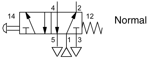 When reset to the normal state at the 12 end port 1 is connected to port 2 (also port 4 is connected to port 5).
Exercise
- A door entry system is controlled by pneumatics. The system makes use of a double-acting cylinder. Part of the circuit diagram is shown below. Complete the diagram, at the link below, so that the door will open and close automatically when fully opened.
Supportive information on the WEB
Standard Symbols for Single Acting Cylinders
 Single-acting, sprung instroked
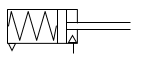 Single-acting, sprung outstroked
 Single-acting, sprung instroked, magnetic
 Single-acting, sprung outstroked, magnetic
Standard Symbols for Double Acting Cylinders
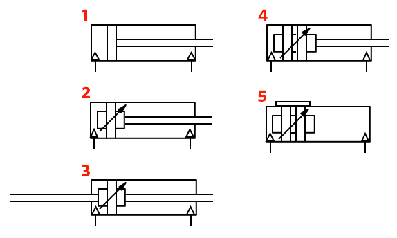
1 Double acting, non-cushioned
2 Double acting, adjustable cushions
3 Double acting, through rod, adjustable cushions
4 Double acting, magnetic, adjustable cushions
5 Double acting, roles, magnetic, adjustable cushions
Example: Parking door with double acting cylinder
- In some applications, especially the one which use high pressures, the piston can move very fast. This can be dangerous or it may prevent the circuit from working properly. To slow down the speed of a piston, we use a flow control valve. There are two types of flow control valves available to us. The first type is called a restrictor (or sometimes a throttle valve). This valve works by reducing the amount of space that the air can flow through. We can adjust the airflow by turning the small screw on top of the valve. The symbol for a restrictor is shown below.
Problems with 3/2 Valves
There are many problems when controlling a double-acting cylinder with two 3/2 valves. It is easy to push or pull the piston. This is because you do not have a constant supply of air to keep the piston in place. When you actuate the 3/2 valve, it outstrokes the piston. When the 3/2 valve is not actuated, air is free to escape or exhaust back through the valve. This means that any force or effort placed on the piston will make it move easily.Question #1 - In a circuit diagram of a pneumatic valve, a pilot signal which control the position of states are denoted by a ___________ .
Question #2 - Which of the following is a disadvantage to use 3/2 valve in a pneumatic system?


-
Logic in Pneumatic Systems
- Logic AND
This involves connecting 3/2 valves together in series. This means that the output from one valve becomes the input to another. The piston outstrokes only valve A and B are operated at the same time. The table, which is also known as Truth Table, summaries every possible operation case.

Valve A Valve B Cylinder Off Off Instroke On Off Instroke Off On Instroke On On Outstroke
Logic OR
- Logic OR
Sometimes we need to control a pneumatic circuit from more than one position. This can be done using OR control circuits. These circuits are quite simple but they need another component called a shuttle valve. A shuttle valve is used to change the direction of air in a circuit. It has a small ball inside that gets blown from side to side. When air is supplied from valve A, the ball gets blown across and the air is directed towards the cylinder. When air is supplied from valve B, the ball is blown to the other side and again the air flows into the cylinder.

Continues on next tabFlow Control Valves
- First type flow control valve Sometimes this can be dangerous or it may prevent the circuit from working properly. To slow down the speed of a piston we use a flow control valve. There are two types of flow control valve available to us. The first type is called a restrictor (or sometimes a throttle valve). This valve works by reducing the amount of space that the air can flow through. We can adjust the airflow by turning the small screw on top of the valve. The symbol for a restrictor is shown below.
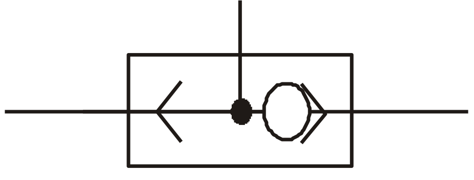
- Second type flow control valve
The problem with this type of restrictor is that it always slows down the speed of the piston in both directions. In many cases, we would only want either the outstroke or the instroke to be slowed down. Also, if we study the piston movement very carefully, we sometimes find that it is quite jerky not smooth as we would want it to be.
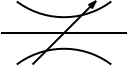
To solve these problems we can use a component called a unidirectional restrictor. As its name suggests, it only slows down the air in one direction. The symbol is shown below.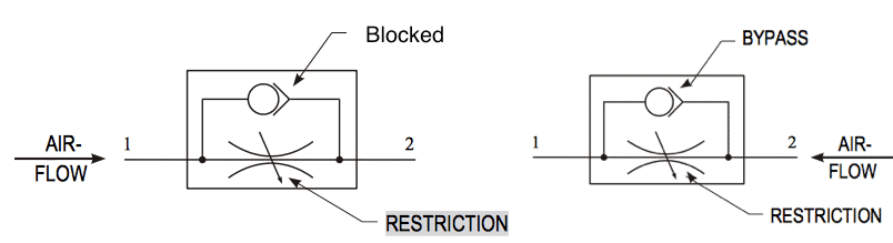
Usage of flow control valves
- The restrictor is placed so that it slows down the exhaust air coming from the cylinder. When ‘valve A’ is pressed, the 5/2 valve changes state and starts to supply the cylinder with air to make it outstroke. Air trapped on the other side of the piston escapes through the restrictor slowly. This makes the piston outstroke slowly. Note that we always restrict the exhaust air coming from a cylinder as this makes the piston move much more smoothly.
- Logic AND
-
Sequential Control: A case Study
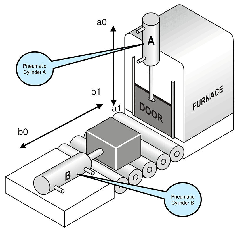 Many pneumatic systems and machines are designed to perform a range of tasks in a certain order or sequence. This usually involves the use of two or more cylinders working together to complete the task.For example, a company has automated its production line that involves metal blocks being placed in a furnace for heat treatment. One cylinder is used to open the furnace door and another pushes the metal blocks into the furnace.
- The sequence of operations for this process is as follows (see diagram above):
An operator pushes a button to start the process. (START)The furnace door is opened. (a0)The block is pushed into the furnace and the piston instrokes. (b1, b0)The furnace door is closed. (a1)The sequence stops.(STOP)
Continues on next tab
Shuttle Valve
- Operation
OR control involves connecting 3/2 valves together in parallel. This means that either valve will outstroke the cylinder.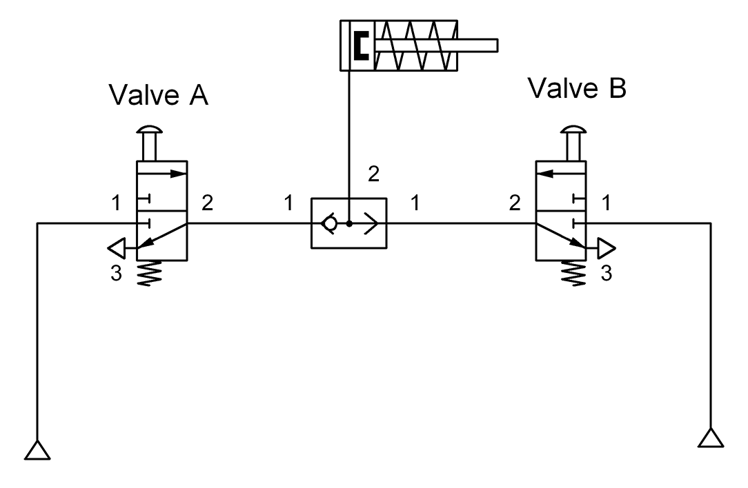
Valve A Valve B Cylinder Off Off Instroke On Off Outstroke Off On Outstroke On On Outstroke
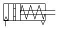
Time Delay
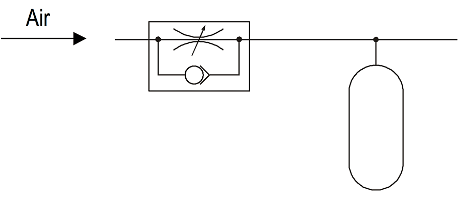 Sometimes in a circuit we want a pause or delay before something else happens. To create a delay we need to use two components – a unidirectional restrictor and a reservoir. A reservoir is simply an empty container, just like an empty bottle. The bigger the reservoir, the longer it takes to fill up with air. To make the delay longer we use a unidirectional restrictor in front of the reservoir. This slows down the air so that the reservoir takes even longer to fill. The length of time it takes to fill creates the delay. We can change the length of a delay by changing the size of the reservoir or adjusting the restrictor.
Question #1 - Sometimes in a pneumatic circuit we want a pause or delay before some action occurs. To create a delay we need to use two components. Which one of the following states these two components?
Question #2 - To activate a single acting cylinder from 2 different air sources one can use________.
-
(Cont.)
- STEP 2
📷 Click here to see STEP 2 diagram
- STEP 3
📷 Click here to see STEP 3 diagram
- STEP 4
📷 Click here to see STEP 4 diagram
- STEP 5
📷 Click here to see STEP 4 diagram
Design of Cascade Circuits: Group Valves for Cascade Connection
 Cascade Valve for 3-Group System
- S1, S2, S3, S4: Group selection pilot inputs.
I, II, III, IV: Group manifolds.
If we need 5 or more groups, the cascade connection can be modified in similar fashion. Cascade Valve for 4-Group System
Continues on next tab
Cascade Valve for 4-Group System
Continues on next tab
Sequential Control: A case Study
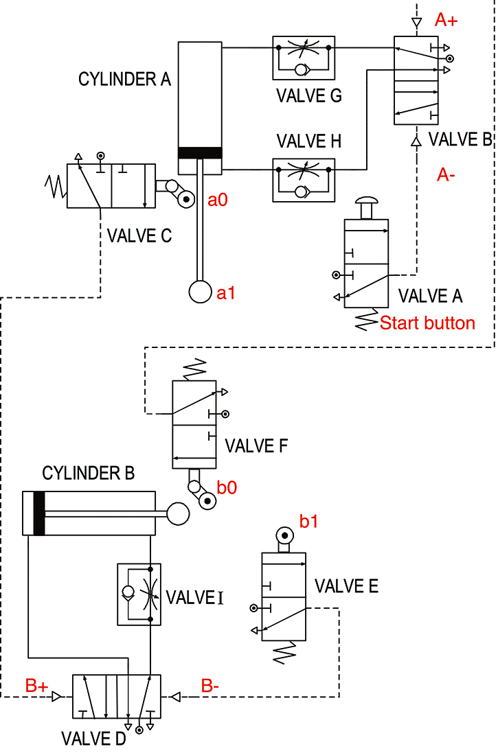
- For this system to work successfully, we need to fully understand the order and movement of cylinders A and B.
1. Cylinder A instrokes to raise the furnace door.
2. Cylinder B outstrokes and pushes the metal block into the furnace.
3. Cylinder B instrokes.
4. Cylinder A outstrokes and closes the furnace door.- The system begins by actuating valve A (START). This changes the state of valve B by (A-) and causes cylinder A to instroke, raising the door.
When fully instroked (a0), or negative, the piston trips valve C and this sends a signal to valve D (B+). This 5/2 valve changes state and sends cylinder B positive.
When fully outstroked (b1), the piston trips valve E (B-) and the cylinder instrokes.
When Cylinder B is negative (b0), valve F is actuated and causes cylinder A to outstroke (A+) and stay in the positive position. The system stops and waits for a signal from valve A, (START BUTTON).
We can summarise the sequence of this circuit as follows. Start, A, B+, B, A+, StopDesign of Cascade Circuits
- STEP 1
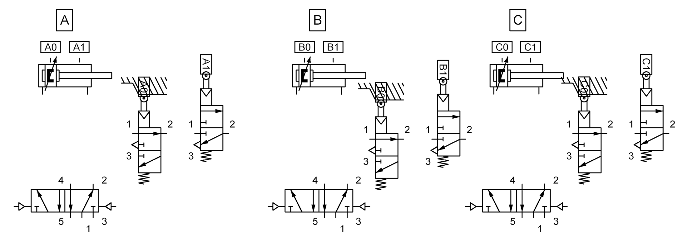
involves dividing the sequence into groups with each group’s manifold (power or main pressure line) being supplied with pneumatic power (pressure) one at a time and in sequence.Motion within each group is powered by its own group manifold.Divide the sequence into Groups so that no letter is repeated within any Group and try obtain minimum number of groups.- Example: Let us build a system that follows the sequence: START, A+, B+, B-, A-, C+, C-

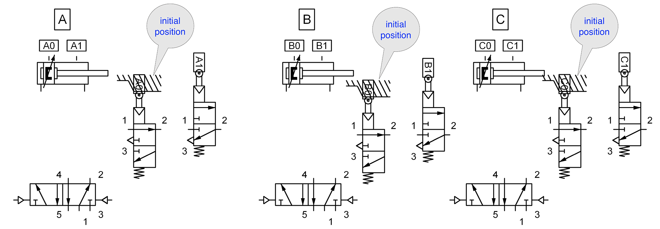
- For each cylinder, assign a label (A,B,C) 5/2 control valve with double pilot lines (i.e., without spring return), instroke and outstroke position labels (A0, A1, B0, etc) and two spring-return double pilot lines (i.e., without spring return) and two spring-return 3/2 limit valves to indicate end of strokes. 3/2 limit valves to indicate end of strokes.
- Assign one or more Group Valves or Cascade Valves to control air pressure to the Group manifold lines so that only one Group manifold line is pressurised at any one time and in sequence. This is important for not to jam the piston.
- Since we have 2 groups, we need 2 independent air manifolds (M1 and M2). When S1 is compressor, air is transferred to manifold M1, and M2 is exhausted. If S2 is activated, compressor air is transferred to M2, M1 is exhausted.
- Here (below) S1 and S2 are
control (pilot) inputs.
- Begin with START. Input to START comes from C0 limit valve and output goes to A+ pilot input of 5/2 valve of cylinder A. Note that A+ motion will trigger A1. Since A1 as well as B1 and C0 are both in Group I, their air supplies must be connected to manifold M1.
- A+ motion will extend cylinder A, which will activate output valve A1. Then A1 will trigger cylinder B to extend.
When B extends, cylinder B triggers B1 which then triggers manifold M2 by pressurising S2.
- Once S2 is pressurised, compressor air is transferred to manifold II, and air in manifold 1 is exhausted. Manifold II also triggers B- to retract cylinder B.
When cylinder B completes its trip, valve at B0 activates cylinder A to retract by pressurising A- input of 5/2 valve attached to cylinder A.
At the end of A- trip, A0 valve activates 5/2 valve of cylinder C to extend. Then, when trip of cylinder C is completed, C1 valve is activated which also activates S1 to transfer compressor air to manifold I. When manifold I is pressurised, this will invoke cylinder C to retract.
This concludes 1 cycle and the system waits in rest until START button is pressed.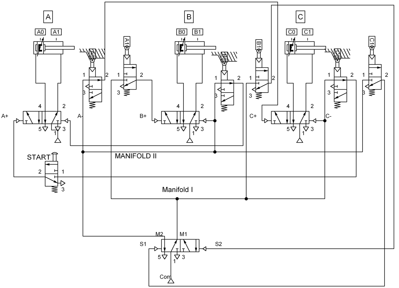
- STEP 2
-
Video Example
The following example considers the design of a pneumatic system using cascade method and it considers the computer simulation of the system (Pneumatic circuit:- ⬇ Pneumatic Example
Design Example
- We would like to design a system which has a single cylinder that operates in the following sequence: START A+ A- A+ A- STOP . Design the pneumatic circuit. This system utilises a single piston but this time it requires 4 end-position sensors (2 ⇥ A0, 2 ⇥ A1 ) positions.

- Example
📷 Click here to see a further Example
- The system has 4 groups. Therefore we need 4 air manifolds and this 4 independent manifold system is a copy of the system shown in the previous slide. Within those 4 independent air manifolds, first one feeds START and A1 valves, second feeds A2, third one feeds A3 and fourth feeds A0 The operation can be described as follows: The start button is pressurised by the air coming from the sensor valve A0 (This is the end of trip of group 4). When the operator pushs the START button, 5/2 valve triggers A+ input to extend. When the cylinder moves to A1, A1 triggers Group 2 by S2. S2 triggers A- input to retract cylinder and this procedure continues in this fashion.

-
Summary
- In this chapter we learned about the components of pneumatic circuits. We started with discussing directional control valves and their applications on common cylinders used in industry. Then we learned about how to design pneumatic circuits and systems to fulfil given complex tasks.