-

Control and Instrumentation Systems
In this part we shall discuss:- Definitions of Hydraulic and Pneumatic Systems
- Comparisons of Hydraulic and Pneumatic Systems
- Pneumatic System components: Compressors
Introduction and Motivation
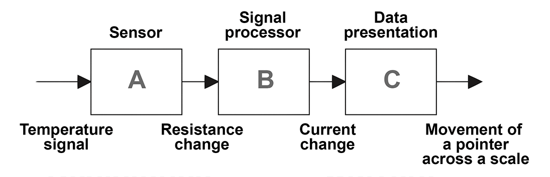
- Actuating systems are the elements of control systems which are responsible for transforming electrical signals into a mechanical action on a machine or device. The electrical signals are generally generated by the control system which utilizes microprocessors or computers. These actions might include conversion of electrical signals to linear or rotary motion or into an action which controls the amount of liquid passing along a pipe.
In this lecture, fluid power systems, namely the hydraulic and pneumatic actuation systems are discussed. A hydraulic drive system is a quasi-hydrostatic drive or transmission system that uses incompressible pressurized hydraulic fluid to power hydraulic machinery. On the other hand, pneumatics has long since played an important role as a technology in the performance of mechanical work. It is also being used in the development of automation solutions. Pneumatic systems are similar to hydraulic systems in many ways. However, in pneumatic systems, compressed air is used in place of hydraulic fluid. Pneumatic systems are widely used in different industries for the driving of automatic machines. We are going to start with discussing key differences between hydraulic and pneumatic systems.
Then we are going to learn about the fundamental components of hydraulic and pneumatic systems. However, we shall focus on pneumatic systems rather than hydraulic systems since pneumatic systems are more common in automation and industry. Also they are much more suitable to work in closed-loop control. -
- The characteristics of incompressible liquids:
The motion, which is caused by fluid entering a chamber, is slow but smooth.Because the motion of the output follows the input, the position and the velocity of the output can be accurately controlled.
- The characteristics of compressible liquids:
Since the compressed air tends to expand quickly, the output reaction is fast.However, the compressed air causes the output motion to be jumpy. Hence, it makes pneumatic systems output difficult to control.- Lubrication
Both systems require lubrication to prevent wearing. Hydraulic systems do not require external lubrication because they are self-lubricate systems. On the other hand pneumatic systems do not use oil. So, an oil mist is often added to the air stream to provide lubrication.
Continues on next tab
Actuators used in Instrumentation and Control Systems: Pneumatic Systems
- Actuation Systems
Actuation systems are the elements of control systems which are responsible for transforming the output of a microcontrollers or microprocessor or control system into a controlling action on machine or device. Therefore, an actuator is a component of a machine that is responsible for moving or controlling a mechanism or system.
An actuator moves or controls loads and mechanisms; the actuator is operated by energy namely either pressurised fluid, air or electricity, typically sourced by utilising a pneumatic, hydraulic or electric pump. The energy is then converted into a motion or force to achieve movement or control.
Pneumatic & hydraulic actuation systems
Pneumatic deals with air pressureHydraulic deals with liquid motion and pressure
- Comparisons
Both hydraulics and pneumatics are defines as fluid power. They use fluid to transmit power from one point to another. In physics, a fluid is a substance that continually deforms (flows) under an applied shear stress. Fluids are a subset of the phases of matter and include liquids, gases, plasmas, and to some extent, plastic solids.
In many ways, hydraulics and pneumatics share the same principles. However, there are a few ways in which they differ.- Transmission of power
The power in both systems is transferred through fluid. But the oil used in hydraulic systems is incompressible, similar to a solid.Pneumatic systems use air. Air is compressible like a spring.Question #1 - Considering pneumatic systems, and hydraulic systems, which statement of the following is false.
Question #2 - Hydraulic systems still require external lubrication
- The characteristics of incompressible liquids:
-
Accumulator
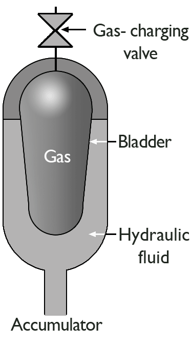 Accumulator is a container in which the oil is held under pressure against an external force, which involves gas within a bladder in the chamber containing the hydraulic fluid.If the oil pressure rises, then the bladder contracts increase the volume the oil can occupy and so reduces the pressure.If the oil pressure falls, the bladder expands to reduce the volume occupied by the oil and so increases its pressure.
Typical Pneumatic System
Pneumatic technology deals with the study of behavior and applications of compressed air in our daily life in general and manufacturing automation in particular. Pneumatic systems use air as the medium which is abundantly available and can be exhausted into the atmosphere after completion of the assigned task.
- 📷 Basic Components of a Pneumatic System
Continues on next tabActuators used in Instrumentation and Control Systems: Pneumatic Systems (cont.)
- Power supply
In a hydraulic system, a pump must be turned on to cause the fluid to flow. Where as, in a pneumatic system, compressed air confined in a tank is released to cause the fluid to flow.
Typical Hydraulic Power Supply
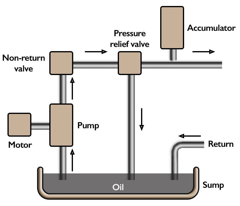 With a hydraulic system, pressurized oil (fluid) is provided by a pump driven by an electrical motor.The pump pumps oil from a sump through a non return valve and an accumulator to the system, from which it return to the sump.The pressure relief valve is to release the pressure if it rises above a safe level.The accumulator is to smooth out any short term fluctuations in the output oil pressure.
-
Receiver Tank size
- There is no generally accepted method of sizing air receivers but a commonly used formula is based on the mass balance: \[ V=t C p_a /(p_1-p_2) \] where \(t\) is the time for the receiver to go from upper to lower pressure limits (min), \(C\) is the free air needed (scfm), \(V\) volume of the receiver tank (cu ft), \(p_a\) is the atmospheric pressure (\(14.7\)psia), \(p_1\) is the maximum tank pressure (psia), and \(p_2\) is the minimum tank pressure (psia).
 Symbol used in block diagrams
- Example
\begin{equation} \begin{split} \\ & V=t C p_a /(p_1-p_2)\\ & = 5 \times \frac{1}{60} \times 1000 \times 14.7 \times (110-100) \\ & =122ft^3 \end{split} \end{equation}
For an air compressor system with mean air consumption \(1000\)cfm, maximum tank pressure \( 110\)psi, minimum tank pressure \(100\) psi and \(5\) sec time for the receiver to go from upper to lower pressure, the volume of the receiver tank can be calculated by:
Basic Components of Pneumatic System
Air Intake Filters are used to filter out the contaminants from the air.Air is generated by using air compressors. Air compressors are either diesel or electrically operated.Since the air compressor increases the temperature of the air, an intercooler is used to reduce the temperatureThe water vapor or moisture in the air is separated from the air by using a dryer.Receiver Tank
- An air receiver is essential to every compressed air system to act as a buffer and a storage medium between the compressor and the consumption system.
The air is compressed slowly in the compressor. But since the pneumatic system needs continuous supply of air, this compressed air has to be stored. The compressed air is stored in an air receiver.
The air receiver smoothens the pulsating flow from the compressor. It also helps the air to cool and condense the moisture present. The air receiver should be large enough to hold all the air delivered by the compressor. The pressure in the receiver is held higher than the system operating pressure to compensate pressure loss in the pipes.
Question #1 - In a basic pneumatic system, it is a common application to use a motor control system between the receiver tank and compressor which is activated by a pressure switch. Which one of the following might be the main reason to use such a motor control block
Question #2 - Which one of the following is the fundamental reason to use a receiver tank in a pneumatic compressor system
- There is no generally accepted method of sizing air receivers but a commonly used formula is based on the mass balance: \[ V=t C p_a /(p_1-p_2) \] where \(t\) is the time for the receiver to go from upper to lower pressure limits (min), \(C\) is the free air needed (scfm), \(V\) volume of the receiver tank (cu ft), \(p_a\) is the atmospheric pressure (\(14.7\)psia), \(p_1\) is the maximum tank pressure (psia), and \(p_2\) is the minimum tank pressure (psia).
-
Piston Type, Double Acting compressor
 The pulsation of air can be reduced by using double acting compressor as shownAs the piston moves, the air is compressed on one side whilst on the other side of the piston, the air is sucked in.Due to the reciprocating action of the piston, the air is compressed and delivered twice in one piston stroke. Pressure higher than 30bar can be produced.For more information about 'Double acting cylinder compressor' click on this link
Piston Type, Multi-stage compressor

The multi-stage compressor can produce a pressure of around 50bar.
Continues on next tab
 Since the graph has a slope of 10 mm/kg, the sensitivity is 10.
Compressor
- The piston compressor (sometimes also called reciprocating compressor) is by far still the most common type of air compressor in use in industry today. It is available in wide range of types and sizes. It is a mechanical device which converts mechanical energy into fluid energy. The compressor increases the air pressure by reducing its volume which also increases the temperature of the compressed air. It is capable of compressing iar up to 1200kPa (12bar) as a single stage compressor and up to 14000kPa (140)bar as a multi-stage compressor.
Pneumatic Compressor Types
- In the positive displacement type, a specified quantity of air is trapped in a compression chamber and the volume which it occupies is mechanically reduced, causing a corresponding rise in pressure prior to discharge.
Positive Displacement Compressors:
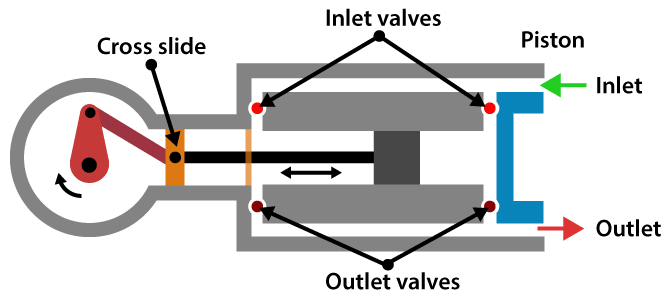
Piston Type, Single Acting Compressor The simplest form is single acting cylinder compressor.It produces one pulse of air per piston stroke. As the piston moves down during the inlet stroke the inlet valve opens and air is drawn into the cylinder.As the piston moves up the inlet valve closes and the exhaust valve opens which allows the air to be expelled.The valves are spring loaded.The pressure developed is about 3-40 bar.For more information about 'Single acting cylinder compressor' click on this link
-
Screw Compressor
 For medium flow and pressure applications, screw compressor can be used.It is simple in construction with less number of moving parts. The air delivered is steady with no pressure pulsation.It has two meshing screws. The air from the inlet is trapped between the meshing screws and is compressed.The contact between the two meshing surface is minimum, hence no cooling is required.These systems are more common then piston type since they are much cheaper.
Vane Compressor
The unbalanced vane compressor consists of spring loaded vanes seating in the slots of the rotor.The pumping action occurs due to movement of the vanes along a cam ring. The rotor is eccentric to the cam ring. As the rotor rotates, the vanes follow the inner surface of the cam ring.The space between the vanes decreases near the outlet due to the eccentricity. This causes compression of the air.These compressors are free from pulsation. If the eccentricity is zero no flow takes place.
Continues on next tab
Question #1 - Diaphragm type compressor is mostly used in ________ industry.
Question #2 - In a combined multi-stage compressor, it is a common application to use an intercooler component. What is the main reason in using an intercooler in this compressor?
Piston Type, Combined Multi-stage compressor
 In this type, two-stage compression is carried out by using the same piston.Initially when the piston moves down, air is sucked in both through the inlet valve and the intercooler.During the compression process, the air moves out of the exhaust valve into the intercooler.As the piston moves further the stepped head provided on the piston moves into the cavity thus causing the compression of air.Then, this is let out by the exhaust port.
Diaphragm Compressor
 These are small capacity compressors. In piston compressors the lubricating oil from the pistons walls may contaminate the compressed air. The contamination is undesirable in food, pharmaceutical and chemical industries.For such applications diaphragm type compressor can be used.The piston reciprocates by a motor driven crankshaft. As the piston moves down it pulls the hydraulic fluid down causing the diaphragm to move along and the air is sucked in.When the piston moves up the fluid pushes the diaphragm up causing the ejection of air from the outlet port. Since the flexible diaphragm is placed in between the piston and the air no contamination takes place.
-
 Axial Compressor
 Centrifugal Compressor
Youtube Centrifugal Compressor video
Since the graph has a slope of 10 mm/kg, the sensitivity is 10.
Lobe Compressor
 Animation by MichaelFrey
The lobe compressor is used when high delivery volume but low pressure is needed. It consists of two lobes with one being driven and the other driving.The animation above shows the construction and working of Lobe compressor. It is similar to the Lobe pump used in hydraulic systems.The operating pressure is limited by leakage between rotors and housing. As the wear increases during the operation, the efficiency falls rapidly.
Animation by MichaelFrey
The lobe compressor is used when high delivery volume but low pressure is needed. It consists of two lobes with one being driven and the other driving.The animation above shows the construction and working of Lobe compressor. It is similar to the Lobe pump used in hydraulic systems.The operating pressure is limited by leakage between rotors and housing. As the wear increases during the operation, the efficiency falls rapidly.
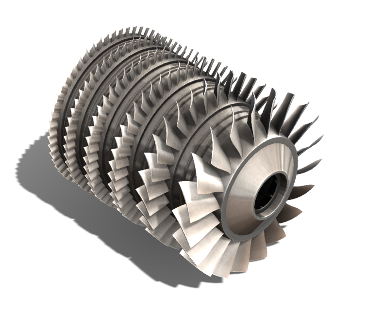
Dynamic Compressors (Turbo Compressor)
When very large volume of compressed air is required in applications such as ventilators, combustion system and pneumatic powder blower conveyors, the dynamic compressor can be used.There are 2 main types of dynamic compressor, they are centrifugal and axial.Centrifugal systems use centrifugal force to hurl air out from the fins, centrifugal systems can generally obtain greater pressures than the axial type compressor.Axial type compressor use a set of fan blades in line to generate large air flow, pressures from this method aren’t expected to reach much over 0.5bar. The axial compressors are largely used for ventilation and as part of air processing.The pressure needed is very low in such applications.The impeller rotates at a high speed. Large volume of low pressure air can be provided by blowers.The blowers draw the air in and the impeller flings it out due to centrifugal force.Positive displacement compressors need oil to lubricate the moving parts, whereas the dynamic compressors have no such need.
-
Components used in air treatment stages
- Inlet Filters
Compressed air requires filtration and drying before it leaves for pneumatic components, atmospheric air carries many particles of debris and moisture that unless filtered out can block valves or cause increased wear. Compressors usually filter air before its compressed, this is mainly to remove relatively large particles which could damage the compressor. A fine grade filter used after it is compressed helps filter the small particles which could clog or damage the pneumatic components that are used in pneumatic system set ups.- Cooler
As the air is compressed, the temperature of the air increases. Therefore the air needs to be cooled. This is done by using a cooler which is also known as a heat exchanger. There are two types of coolers commonly used. These are air cooled and water cooled coolers. In the air cooled type, ambient air is used to cool the high temperature compressed air, whereas in the water cooled type, water is used as cooling medium. These are counter flow type coolers where the cooling medium flows in the direction opposite to the compressed air. During cooling, the water vapor present will condense which can be drained away later.- Mainline Filters
These filters are used to remove the water vapours or solid contaminants present in the pneumatic systems main lines.
Please watch the animation to understand the working principle
Air Treatment in Pneumatic Systems
- These particles can cause wear of the system components and presence of moisture may cause corrosion. Compressors usually filter air before its compressed, this is mainly to remove relatively large particles which could damage the compressor. A fine grade filter used after it is compressed helps filter the small particles which could clog or damage the pneumatic components that are used in pneumatic system set ups. Atmospheric air is polluted with dust, smoke and is humid. . Hence it is essential to treat the air to get rid of these impurities. The air treatment can be divided into three stages as shown in next slide.
Air Treatment Stages
- 📷 Air Treatment Stages - larger diagram
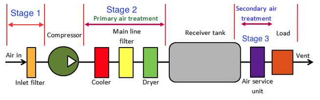 In the first stage, the large sized particles are prevented from entering the compressor by an intake filter.The air leaving the compressor may be humid and may be at high temperature. The air from the compressor is treated in the second stage. In this stage temperature of the compressed air is lowered using an inter-cooler and the air is dried using a dryer. Also a line filter is provided to remove any contaminant particles present. This treatment is called primary air treatment.In the third stage which is the secondary air treatment process, further filtering is carried out. A lubricator introduces a fine mist of oil into the compressed air. This will help in lubrication of the moving components of the system to which the compressed air will be applied.
Question #1 - Which one of the following is the main function of an inlet filter in pneumatic systems?
Question #2 - In the primary air treatment stage how many different components are used?
- Inlet Filters
-
Absorption Air dryer
 This system uses chemical substances like phosphoric pentoxide or calcium chloride for drying purposes.The moisture in the compressed air chemically reacts with the drying agent. The agent dissolves to form a liquid compound which collects at the bottom of the dryer where it can be drained out.The deliquescent agent has to be refilled regularly since it gets consumed during the drying process.
Lubricator
 The following video explains how to set up a rublicator and a regulator: lubricator and regulator system
- The compressed air is first filtered and then passed through a lubricator in order to form a mist of oil and air to provide lubrication to the mating components. The compressed air from the dryer enters in the lubricator. Its velocity increases due to a pressure differential between the upper and lower changer (oil reservoir). Due to the low pressure in the upper chamber the oil is pushed into the upper chamber from the oil reservoir, without an external power, through a tube with a adjustable valve. The main function of the valve is to control the amount of oil passing through it. The oil drops inside the throttled zone where the velocity of air is much higher and this high velocity air breaks the oil drops into tiny particles. Thus a mist of air and oil is generated. The pressure differential across chambers is adjusted by a needle valve. It is difficult to hold an oil mixed air in the air receiver as oil may settle down. Thus air is lubricated during secondary air treatment process.
Since the graph has a slope of 10 mm/kg, the sensitivity is 10.
Components used in air treatment stages (Cont.)

- Filter and Water Trap
Air filter and water trap is used toprevent any solid contaminants from entering in the system.condense and remove water vapour that is present in the compressed air.The thickness of sintered cartridge provides random zigzag passage for the air to flow-in which helps in holding the solid particles.The air entering the filter produces a whirlpool by the help of deflector cone. This centrifugal movement of the air causes the large contaminants and water vapour to be hurled, which then hit the glass bowl and at the end get collected at the bottom.A baffle plate also provided to prevent the turbulent air from splashing the water into the filter cartridge.At the bottom of the filter bowl, there is a drain which can be opened manually to remove the dirty water contaminated by solid particles.
Refrigerated Air Dryer
 The following video explains working principle of a refrigerated dryer system:
This system is consisted of two heat exchangers, a refrigerant compressor and a separator. The dryer cools the air just above \(0^o \mathrm C\) which condenses the water vapour.Then the water is collected by the separator. However such low temperature is useless for the most of the applications. Therefore, this cooled air is also used to cool the high temperature air coming out from the compressor at heat exchanger 2. The moderate temperature dry air coming out from the heat exchanger 2 is then used for actual application.
-
(Cont.)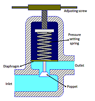
- In a non-relieving pressure regulator, the outlet pressure is sensed by a diaphragm which is preloaded by a pressure setting spring. If outlet pressure is too low, the spring forces the diaphragm and poppet to move down thus opening the valve to admit more air and raise outlet pressure. If the outlet pressure is too high the air pressure forces the diaphragm up hence reduces the air flow and causing a reduction in air pressure. The air vents away through the load. At steady state condition the valve will balance the force on the diaphragm from the outlet pressure with the pre-set force on the spring.
The summary of the air preparation
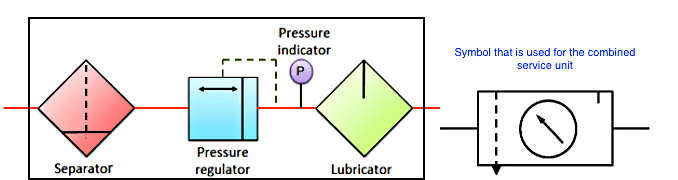
The following video summarizes the overall system which allows to obtain dry, regulated and clear air: click here for video link- During the preparation of compressed air, various processes such as filtration, regulation and lubrication are carried out by individual components. The individual components are: separator/filter, pressure regulator and lubricator.
Sometimes, these functions can be combined into one unit which is called as service unit.
- 📷 Service Unit - larger diagram
Since the graph has a slope of 10 mm/kg, the sensitivity is 10.
Pressure Regulation
- Why do we need regulation of air pressure?
In pneumatic systems, during high velocity compressed air flow, there is flow-dependent pressure drop between the receiver and load (application). Therefore the pressure in the receiver is always kept higher than the system pressure. At the application site, the pressure is regulated to keep it constant. Regulator Symbol
Pressure Regulation with a relief valve:
How does it work? The following video explains working principle of a regulator:click here for the regulator system
- Relief or relieving valve is the simplest type of pressure regulating device. It has a vent on itself. This device consists of ball type valve held on to the valve seat by a spring in tension. The spring tension can be adjusted by using the adjusting cap. When the air pressure exceeds the spring tension pressure, the ball is moves from its place, thus releasing the air and reducing the pressure. A relief is specified by its span of pressure between the cracking and full flow, pressure range and flow rate. Once the valve opens, flow rate depends on the excess pressure. Once the pressure falls below the cracking pressure, the valve seals itself.
-
Summary
Hydraulic and pneumatic systems: A hydraulic drive system is a quasi-hydrostatic drive or transmission system that uses incompressible pressurized hydraulic fluid to power hydraulic machinery. On the other hand, pneumatics systems are similar to hydraulic systems in many ways. However, in pneumatic systems, compressed air is used in place of hydraulic fluid. Pneumatic systems are widely used in different industries for the driving of automatic machines.
The power in both systems is transferred through fluid. But the oil used in hydraulic systems is incompressible, similar to a solid. Therefore, it is easy to control hydraulic systems. However, pneumatic systems use air. Air is compressible like a spring which makes these systems difficult to control
Hydraulic and pneumatic systems are quite similar in nature. Both systems require pump, lubrication, accumulator. However hydraulic systems do not require external lubrication as pneumatic systems do. The second big difference is that hydraulic systems are closed which means that oil circulates within the system and never leaves it unless there is a fault within the system, whereas pneumatic systems are considered as open systems in which the air can be exhausted and therefore always must be replaced by the compressor.
Hydraulic systems generally work quite slow compared to their pneumatic counterpart. They are widely used and accepted in heavy industry which might require transfer and control of huge powers. On the other hand, pneumatic systems work considerably faster than hydraulic systems and they are widely accepted in automation systems. Therefore, we have concentrated on pneumatic systems rather than hydraulic ones.
A basic pneumatic system involves inlet filter which removes large particles taken from the atmosphere, a compressor which moves air in the system, an air cooler which cools down the hot compressed air generated by the compressor, a separator which separates water or mist from the air, a receiver tank which accumulates the air and provides a constant pressure, valves which direct the air within the system like the relays in electrical systems and cylinders which transform air into motion.