11
-
Introduction
- Graphs provide a rich and powerful way to model relations in complex problems. Graphs can be used to model many real world problems, such as network and transport links.
- This week we will:
- Review basic graph terminology.
- Cover implementation details of different kinds of graphs.
- Study possible uses of graphs.
-
Definitions
- Vertex – a node in a graph
- Edge – link connecting two nodes (relationship)
- Adjacent – two nodes connected by an edge
- Undirected Graph - a graph in which the edges have no directional component. It is possible to move in both directions along an edge between two vertices
- Directed graph (digraph) - a graph in which the edges have directional components. It is possible to move from one vertex to the other only in the indicated direction
- Path – a sequence of distinct vertices, each adjacent to the next
- Cycle – a path containing at least three vertices such that the last vertex is adjacent to the first
- Connected graph – an undirected graph in which there is a path from any vertex to any other vertex
- In-degree – the in-degree of a node is the number of edges that end at that node
- Out-degree – the out-degree of a node is the number of edges that start at that node
- Network – a graph in which the edges are weighted
- Weighted graph – a weighted graph is a graph with weights/cost assigned to each edge
- Graph – represents relationship among nodes, and is defined as a set of vertices (V) and a set of edges (E)
-
Adjacency
- Two nodes that have an edge connection between them are said to be adjacent. If the edge is directed then the adjacency will only be as dictated by the edge direction.
- Vertices
- The vertices in the graph above can be represented as,
- $$ V = \{0, 1, 2, 3, 4, 5, 6 \} $$
- Edges
- The edges in the graph can be represented as:
- $$ E = \{\{0, 1\}, \{0, 5\}, \{0, 6\}, \{1, 2\}, \{1, 3\}, \{1, 5\}, \{2, 6\}, \{3, 2\}, \{4, 3\}, \{5, 3\}, \{6, 5\}\} $$
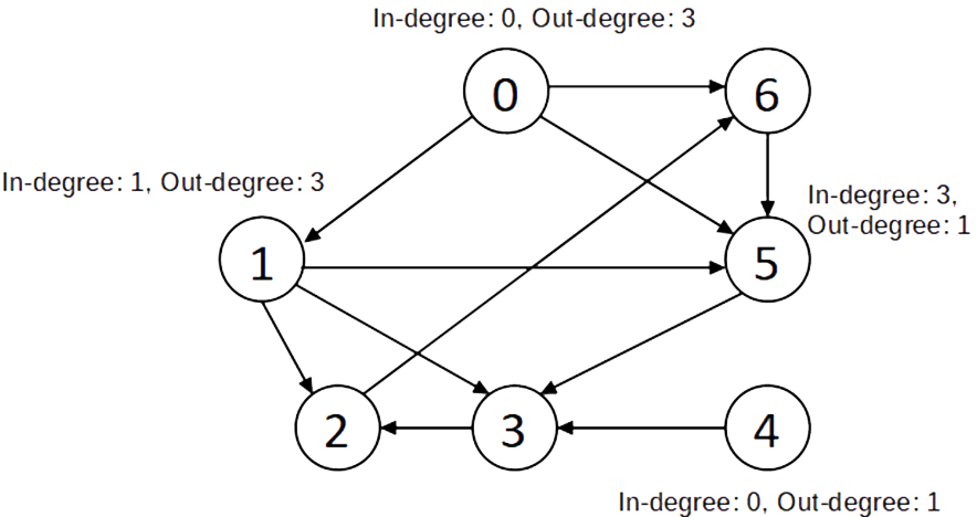
- In-degree and Out-degree
- In and Out-degree for few of the vertices are as shown:
- Adjacency
- For the above graph, the vertices adjacent to vertex 5 is vertex 3 and those adjacent to vertex 1 are {2, 3, 5}.
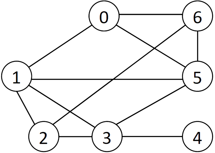
- Undirected graphs
- In an undirected graph it is possible to move in both directions along an edge between two vertices.
- Vertices
- Each vertex is part of the set V of vertices in the graph
- $$ V = \{0,1,2,3,4, 5, 6\} $$
- Edges
- Each edge can be represented as a pair of vertices
- $$ E = \{\{0, 1\}, \{0, 5\}, \{0, 6\}, \{1, 2\}, \{1, 3\}, \{1, 5\}, \{2, 6\}, \{3, 2\}, \{4, 3\}, \{5, 3\}, \{6, 5\}\} $$
- Adjacency
- For the above graph, the vertices adjacent to vertex 5 are {0, 1, 3, 6} and those adjacent to vertex 1 are {0, 2, 3, 5}.
An Example Digraph (directed graph) 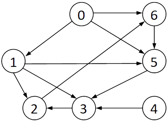
-
Graph ADT Operations
-
addVertex( ) - creates a new vertex
addEdge( ) - creates a new edge
removeVertex( ) - removes the vertex and its associated edges
removeEdge( ) - removes the edge
vertexSize( ) - returns the number of vertices in the graph
edgeSize( ) - returns the number of edges in the graph
inDegree( ) - returns number of incoming edges to a vertex
outDegree( ) - returns the number of outgoing edges from a vertex
adjacent( ) - checks if the given vertices are adjacent
-
-
Graph Representation
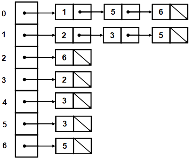
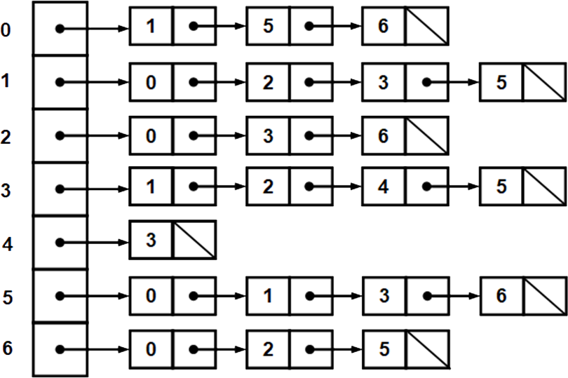
- Adjacency List for a directed graph
- This representation uses a linked list to represent the set of adjacent vertices. The connectivity (adjacency) of each vertex can then be represented through a linked list.
- The out-degree of each vertex can easily be counted using this representation e.g., vertex 3 doesn’t connect to any other vertices, out degree is 0. Vertex 1 connects to 3 others and has an out-degree of 3. For the in-degree count number of times a vertex appears in the list of connected nodes e.g., vertex 2 appears twice, in-degree is therefore 2.
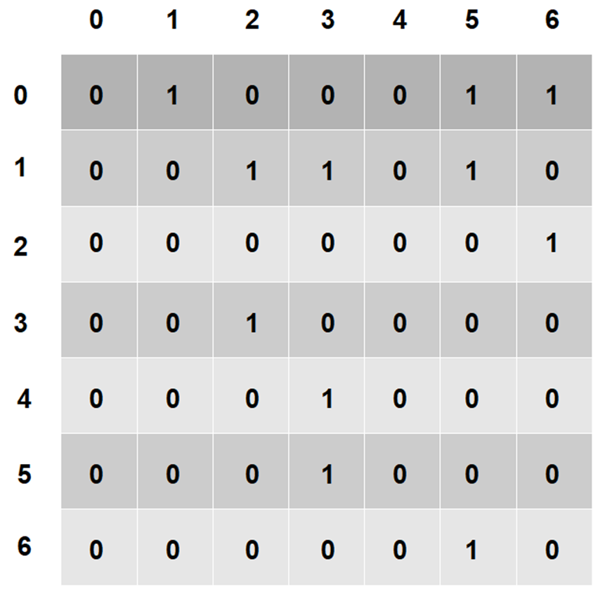
- Adjacency Matrix for a directed graph
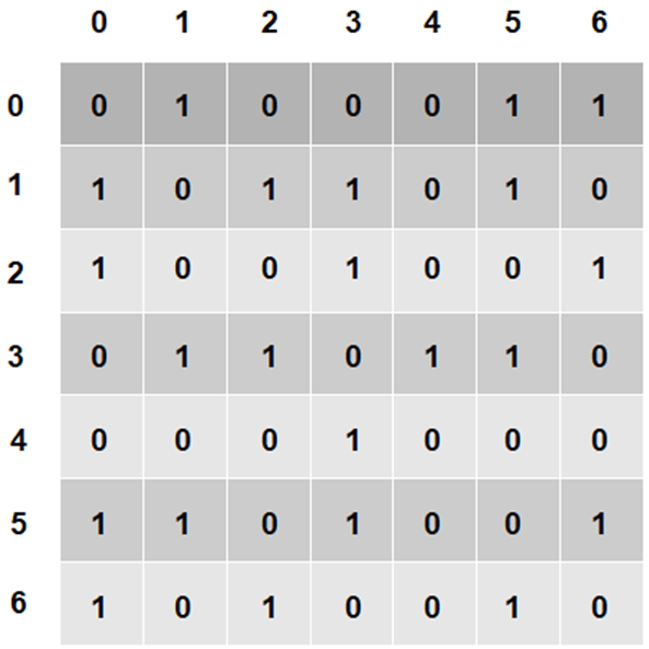
- In case of an undirected graph (shown above), the matrix will be symmetrical, that is, both A(i, j) and A(j,i) values would be the same. For example consider A(3,4) and A(4,3) being 1 indicating that one can move from 3 to 4 and also from 4 to 3.
- Adjacency Matrix for the undirected graph
- Characteristics of Adjacency List
- No wasted memory space.
- Sequential access only to find adjacent access.
- Characteristics of Adjacency Matrix
- Space is wasted.
- Easy to determine adjacency.
A directed graph. 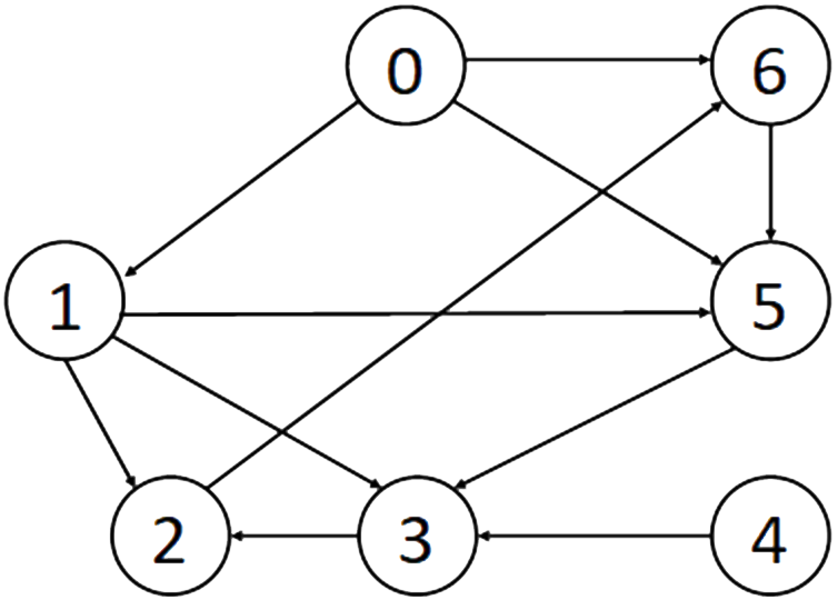
An undirected graph. 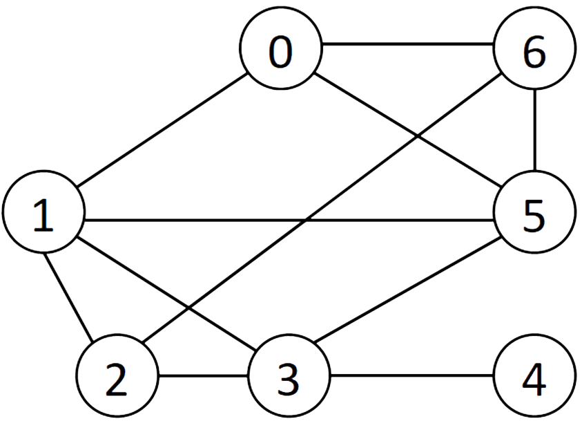
-
Graph Application
- Shortest path
- Determine the shortest path between a given vertex and other vertices. This is important to reduce costs significantly through efficient routing of goods and services.
- Critical path analysis
- Critical Path Analysis helps you to identify the minimum length of time needed to complete a project. Any delay on the critical path events are likely to delay the whole project. Thus the project can be completed in the allocated time by allocating resources appropriately.
-
Shortest Path Algorithm - Introduction
- Many real world problems require computing the shortest path in a network. This is very important problem to solve for transport links, networks, pipelines etc. For such problems we can associate a cost to each edge (that is a weighted graph) and then measure the least cost that would be involved between any two given nodes. The cost could be a measure of distance for example in a transportation link. One popular algorithm to find the shortest path between a given vertex and all other vertices is Dijkstra’s algorithm.
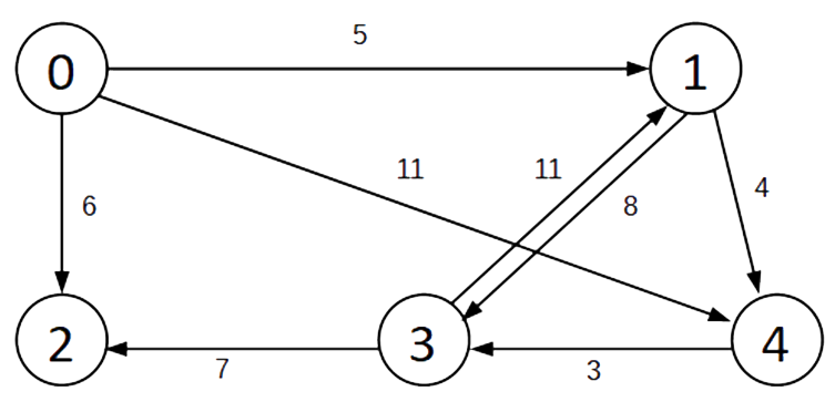
- A weighted graph
- A weighted graph will have a weight assigned to the edges. It is possible to have an edge between two vertices have a different weight in each direction. An example weighted graph is shown below.
- Shortest path
- The shortest path between any two vertices is the one with the smallest sum of the weighted edges
- Example: what is the shortest path between vertex 0 and vertex 3?
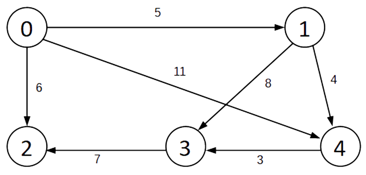
- Shortest path problem
- Consider the following graph. We need to determine the shortest path from the vertex 0 to vertex 3.
- There are two paths to consider:
- Path 1: 0 → 1 → 4 → 3
- Path 3: 0 → 1 → 3
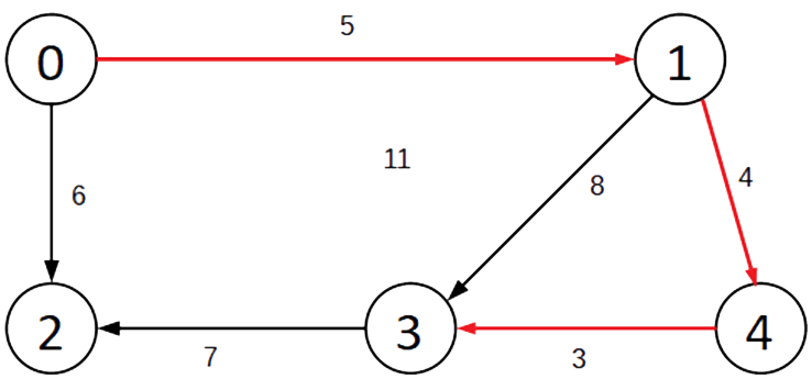
- by calculating the edge weights it can be found that the path 0 → 1 → 4 → 3 as shown on the graph with red lines is the shortest path in getting from vertex 0 to vertex 3.
-
Summary
- A graph ADT is used to represent the relationships between nodes such as in a network.
- The graph can be implemented either as an adjacency list or an adjacency matrix.
- There are many applications of graphs such as finding the shortest path or the critical path.