05
-
NRM2 Work Section 11 In-situ Concrete Works
- Concrete can be either:
- 🔗 In-situ concrete - NRM2 Work Section 11
- Precast/composite concrete - NRM2 Work Section 12
- Precast concrete - NRM2 Work Section 13
 Concrete:
Is often used for curves and complex, organic shapes / structures
Has diverse uses; statement buildings to car parks
Can have a variety of finishes; Impressions, Etchings, Timber effect- Work Section 11 In-situ concrete works notes the following 📷 items or works to be measured within this work section
- In-situ concrete : 1-7 (7)
- Surface finishes to in-situ concrete : 8-12 (5)
- Formwork : 13-32 (20)
- Reinforcement : 33-37 (5)
- Designed joints in in-situ concrete : 38-40 (3)
- Accessories cast in to in-situ concrete : 41 (1)
- In-situ concrete sundries : 42-44 (3)
- The Work Section begins by detailing the information you should have provided prior to undertaking the measurement task and lists the works and materials deemed included. It is very important to read and understand this 📷 table prior to measuring.
Some specific points to note :- Identify work in substructures, superstructures or external works separately and state explicitly
- Concrete is measured NET – no deduction for formwork, reinforcement, chairs/stools, accessories, voids (except troughed and coffered slabs)
- Concrete is deemed cast into formwork unless otherwise described
- Concrete deemed finished ‘as struck’, deemed tamped finished, horizontal
In-situ Concrete Works
- Prior to the ‘Item or work to be measured’ itself, NRM2 states that in-situ concrete must be classified as one of the following 📷 types:
- (Items in blue are generally the most common types)
- Plain in-situ concrete
- Reinforced in-situ concrete
- Fibre reinforced in-situ concrete
- Sprayed in-situ concrete
- Note that this choice of type before the ‘Item or work to be measured’ is a little different to many other work sections within NRM2.
- Once the type has been classified, each different concrete mix is measured separately; reinforced Mix A or reinforced Mix B etc; Concrete itself is measured in ‘m3’
- * only ever in ‘m2’ for sprayed in-situ (item 11.7)
- * only ever in ‘m’ for sundry work not exceeding 300 wide or thick (item 11.6.1)
- Work is described as mass, horizontal, sloping or vertical
Work is predominantly described in either: not exceeding 300 thick / wide or exceeding 300 thick / wide- Concrete can be measured and described:
- Either collectively, in ‘aggregate’
OR
The volumes of each type of work can be given separately- Item or work to be measured 1 : Mass Concrete

- Mass Concrete is UNREINFORCED bulk concrete work of any thickness and has no formwork
Possible Application/Example: 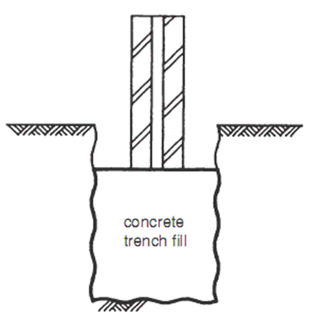
- Item or work to be measured 2 : Horizontal Work, 3 : Sloping work ≤ 15° and 4: Sloping work ≥ 15°
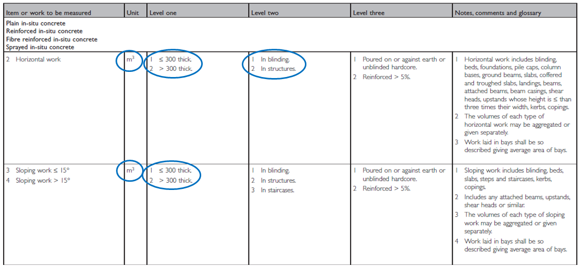
- Level One:
Works are described as not exceeding 300 or exceeding 300 thick
Level Two:
1. In blinding: generally foundations and ground beams laid on blinding or beds laid on sand / whin dust blinding
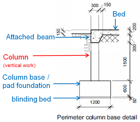
2. In structures is used (some choose to further describe as in substructures)- Here is an example of typical horizontal/sloping works within substructure: (Hover mouse over image below for additional information).
- Item or work to be measured 5 : Vertical Work

- Again, vertical work is also measured in ‘m3’ and described as either not exceeding 300 or exceeding 300.
- The volumes of each type may be given in aggregate or separately
- Note that 📷 ‘Filling to hollow walls’ is essentially cavity fill
- Item or work to be measured 6 : 📷Sundry In-situ Concrete Work
- Any other in-situ concrete works which are not classified in Items 1-5 are measured within Item 6 Sundry works. This includes works such as backsills, machine and plant bases
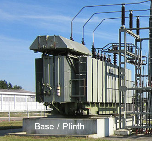 and the like.
This item also provides in Level One the need to describe whether the width (not just the thickness as previous items) does or does not exceed 300.
Depending on the thickness or width of the works, they are measured in either ‘m’ or ‘m3’
The works are then further described in Level Two as horizontal, sloping or vertical.
and the like.
This item also provides in Level One the need to describe whether the width (not just the thickness as previous items) does or does not exceed 300.
Depending on the thickness or width of the works, they are measured in either ‘m’ or ‘m3’
The works are then further described in Level Two as horizontal, sloping or vertical.- Item or work to be measured 7 : 📷Sprayed In-situ Concrete Work
- The last item for the concrete itself is sprayed in-situ concrete work
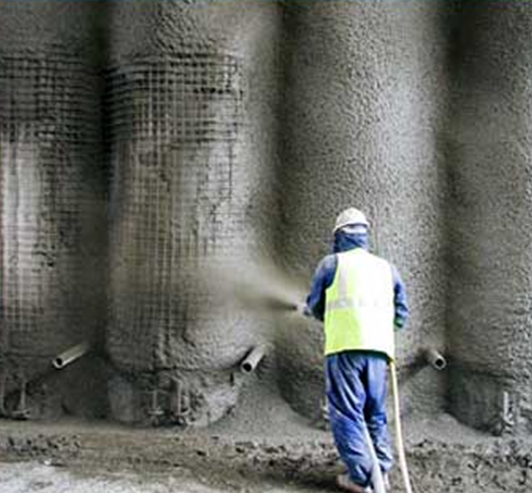 This is measured in ‘m2’ with the thickness, method of application and finish stated within the description.Levels 2 and 3 require the location and nature of location to be described.
Surface Finishes to In-situ Concrete Work

- All top surfaces of in-situ concrete are deemed to have a tamped finish (rule 7)
- Surface finishes are measured in ‘m2’ regardless of width
- (Hover mouse over photographs below for additional information).
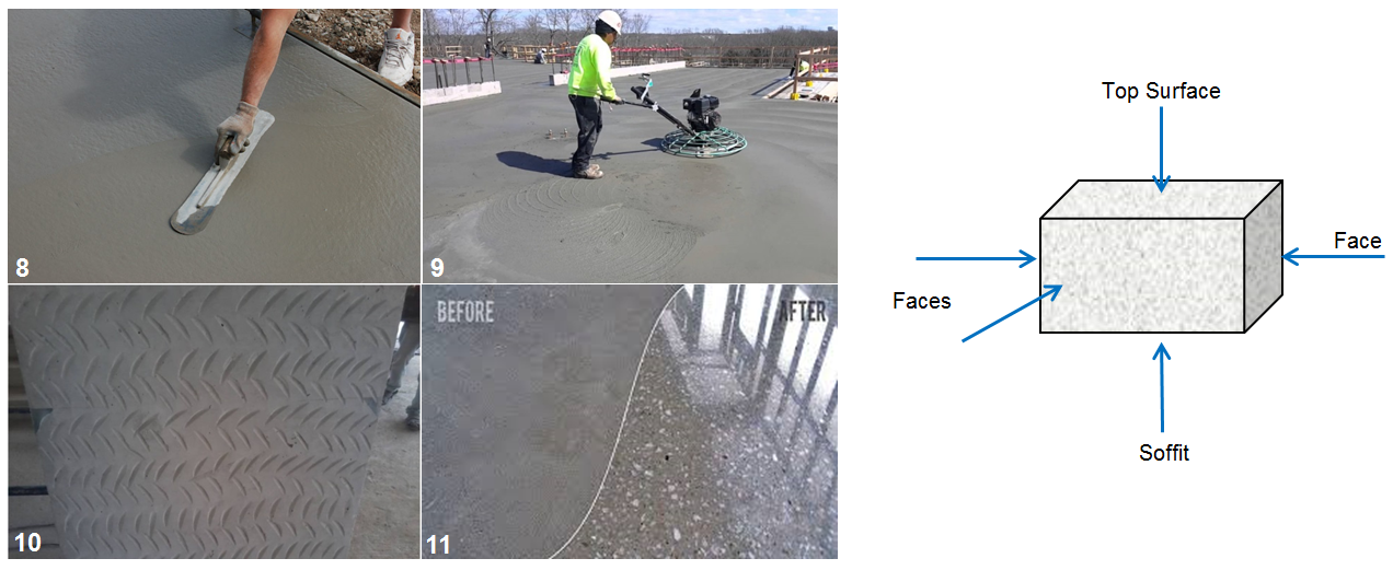
Formwork
- Formwork is a material used to contain, support and form concrete until it has gained sufficient strength to be self-supporting. Formwork can be temporary or left in permanently.
- (Hover mouse over photographs below for additional information).
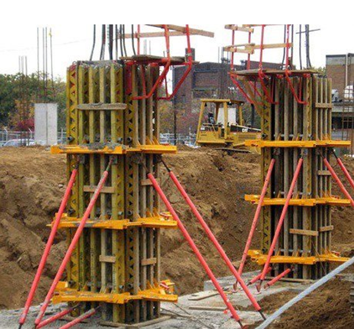
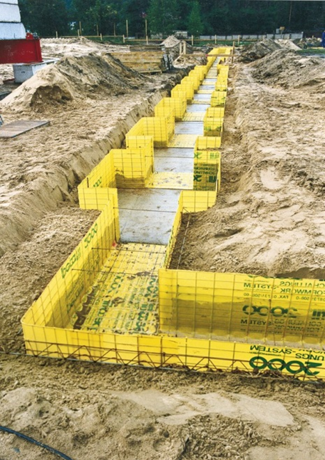
- Within NRM2, the beginning of the 📷 formwork section ‘Notes, comments and glossary’ explains 10 points in relation to formwork measurement and description as well as those items deemed included or as standard. It is important to read and understand these prior to taking off any dimensions.
- Unlike in-situ concrete itself, NRM2 requires each type of formwork to be measured and billed separately (items 📷13-21 and 📷22-32) e.g.
- Sides of foundations and bases
- Edges of horizontal work
- Sides and soffits of beams
- Sides of attached columns
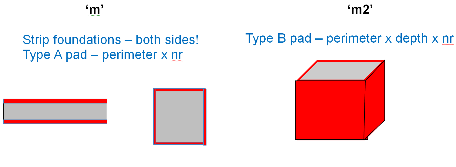
- An example of formwork for a strip foundation and pad foundations is shown above.
- Note the different units of measurement and also note the different types of categorising work within Level One:
- Height
- Concrete thickness
- Shape regularity (📷see notes 1 and 2 highlighted for shape regularity)
- Note: formwork would not be required for cavity fill as the masonry walls would be supporting the concrete.
- Example :
- Strip foundation : 600 x 150 deep
- Type A pad foundation : 2100 x 2100 x 450 deep
- Type B pad foundation : 3000 x 5000 x 550 deep
- Sides of foundations and bases
- Not exceeding 500 high – measured in ‘m’ - strip and Type A pad
- Exceeding 500 high – measured in ‘m2’ – Type B pad
- 🔗 23 Extra over and 31 Complex shapes
Reinforcement
- Items or work to be measured 33 – 37 relate to 📷concrete reinforcement.Things to note about reinforced concrete:
- Reinforced concrete needs formwork (chairs/stools) to maintain the ‘cover’ to the reinforcement
- When pouring reinforced concrete on earth or hardcore, a blinding layer of weak mix concrete is necessary
- No deduction is made for the volume of reinforcement – concrete is NET!
- Some examples of reinforcement are shown below:
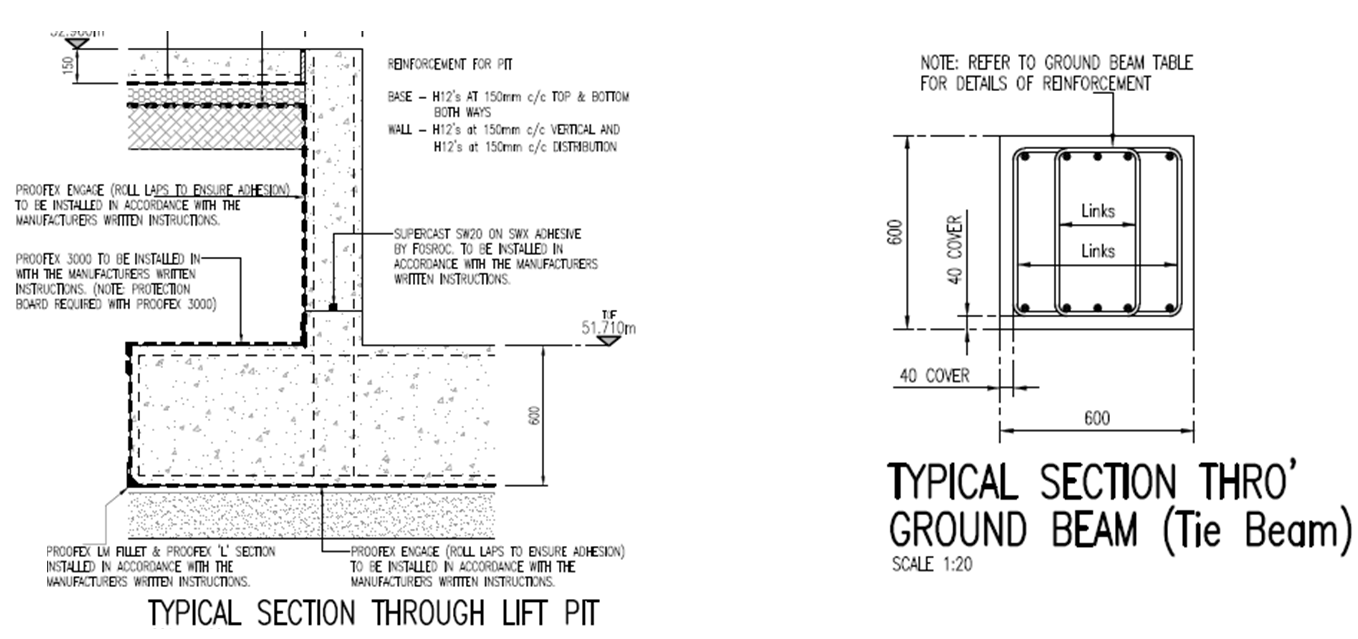
- Item or work to be measured 33 : Mild Steel Bars and 34 : High Yield Steel Bars
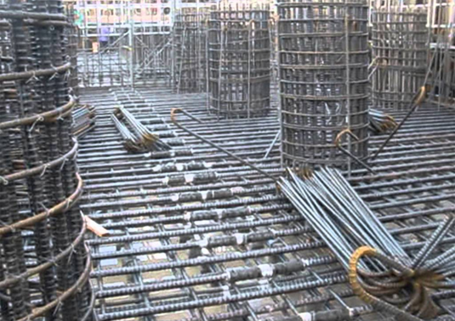
- Items 33 and 34 reinforcement bars are measured in ‘t’, remember this means they are billed to 2 decimal places!
- Generally, the tonnage for reinforcement bars is taken directly from the engineers bar bending schedule (an example of a bar bending schedule is within the supplementary information tab)
- Item or work to be measured 37 : Mesh
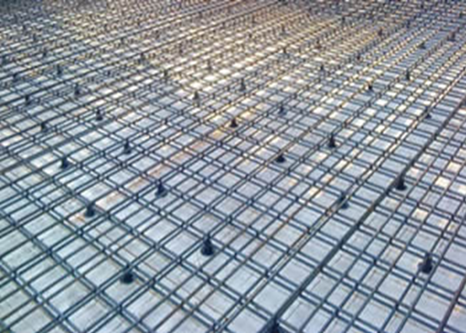
- Item 37 reinforcement mesh is measured in ‘m2’
- All laps, stools, chairs and supports are deemed included
- Voids < 1.00m2 are not deducted
- The weight per m2 and fabric reference is stated. Weights per m2 can be found from steel manufacturers and the fabric reference should be within the specification
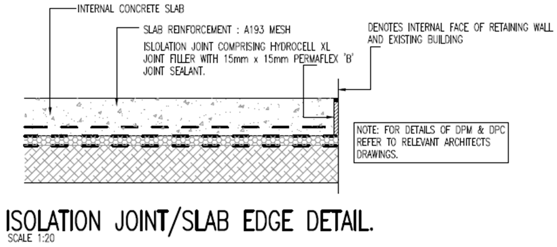
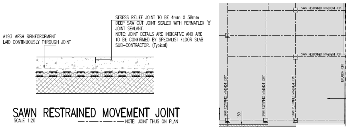
Designed Joints in In-situ Concrete
- Joints NOT located at the discretion of the Contractor, MUST be measured – See note 1
- Joints at the discretion of the contractor would include construction day joints etc…
- Some joints will also be at the discretion of specialists – such as flooring or screed subs
- Joints are 📷measured in linear ‘m’
- "Details of primers, cleaners, fillers, waterstops, backing strips, reinforcement, ties, sealants, the method of application, preparation and the like, shall be stated in the description."
- All preparation, cleaners, primers, sealers, angles, ends and the like are deemed included
- Joint types include:
- Plain (do not require formwork – see note 1)
- Formed (require formwork, deemed included – see note 2)
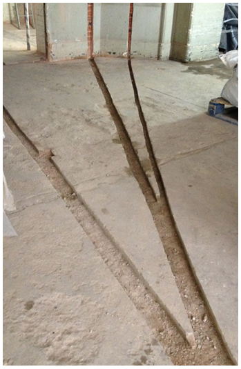
- Cut
- The following are deemed included:
- preparation, cleaners, primers, sealers
- angles, ends, intersections regardless if formed, welded or purpose made
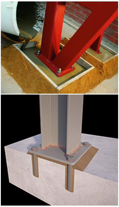
- 📷Accessories Cast Into In-situ Concrete
- Accessories cast into in-situ concrete must have the kind, quality and size or the manufacturers reference stated.
- The unit of measurement differs depending on the item, however, note Level Two which states that linear or superficial quantities must describe any appropriate spacing dimensions.
- The ‘Notes, comments and glossary’ column has detailed information regarding which accessories are included or excluded.
- 📷In-situ Concrete Sundries
- The final group of items or works to be measured within the Work Section is in-situ concrete sundries.
- All require a dimension description and all necessary formwork or temporary support is deemed included.
 x
x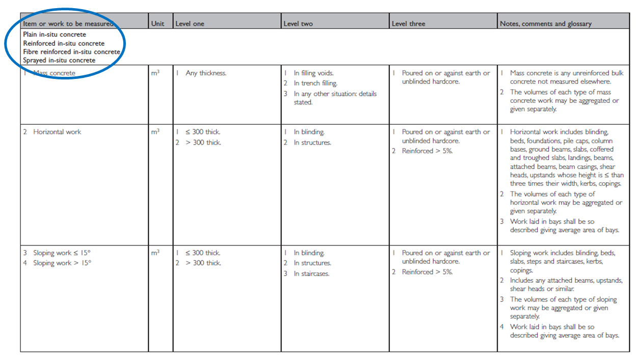 x
x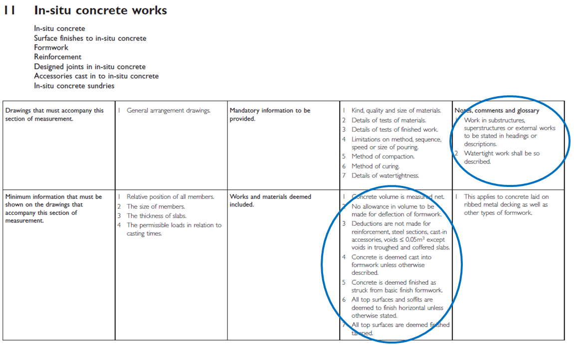 x
x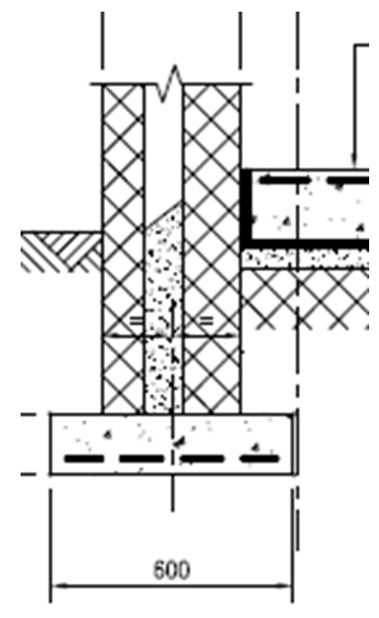 x
x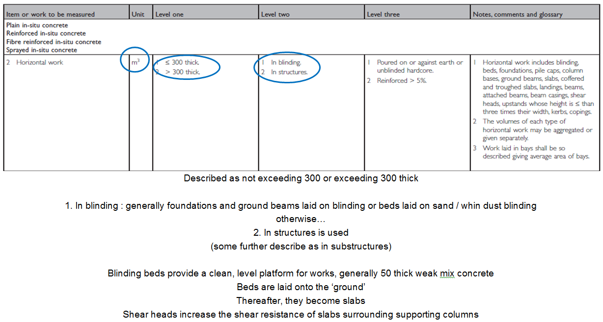 x
x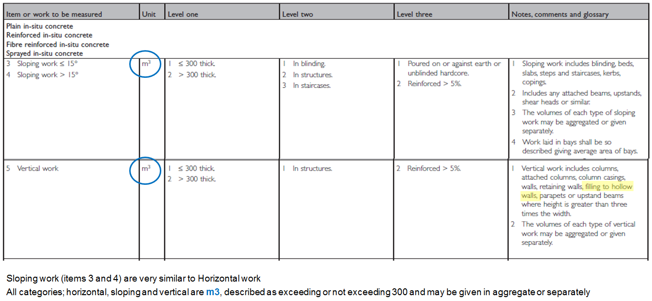 x
x x
x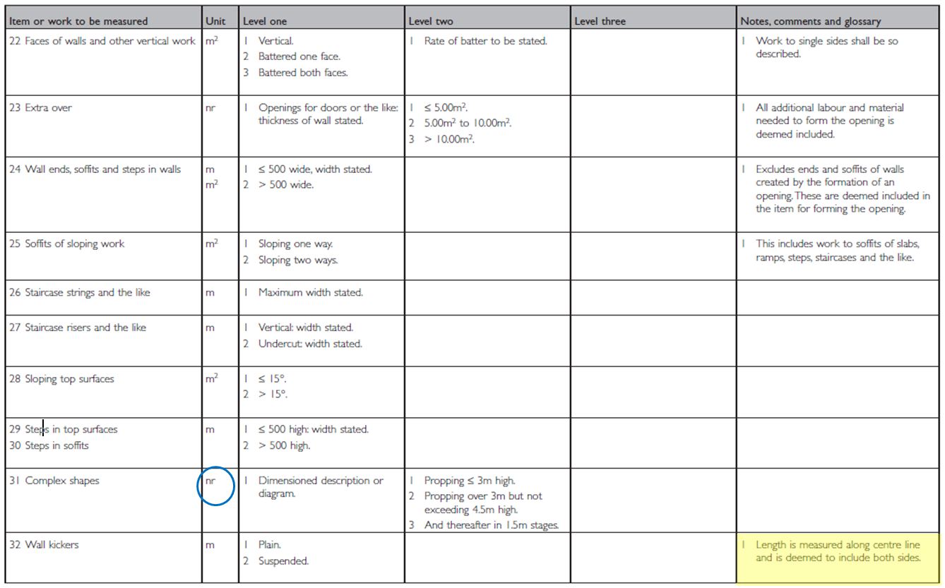 x
x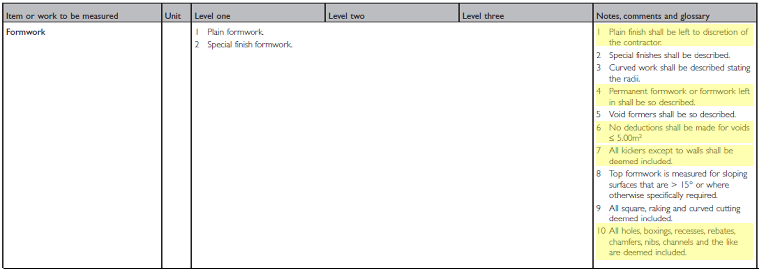 x
x x
x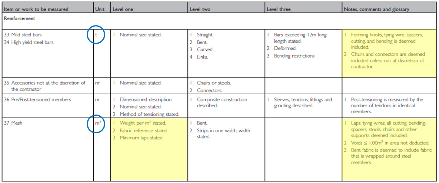 x
x x
x x
x x
x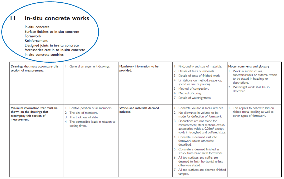
-
The Task
- Take off the quantities for the superstructure concrete frame (including excavation works).
- Starting your measurement task
- Gather all the materials you may need:
- Dimension paper/Take off Sheet
- Standard / Method of measurement
- Scale Rule
- Query Sheet
- Gather all the information:
- Drawings
- Specifications
- Schedules
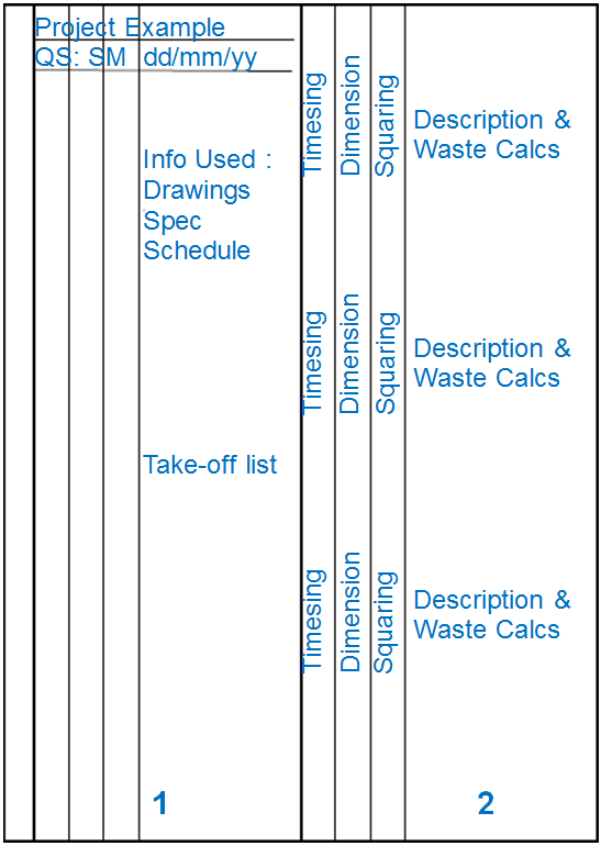
- Set up your Dimension Paper/Take off Sheet:
- Project Title / Reference
- Surveyor Reference / Initials
- Date
- Number the columns/pages
- List information used/Work Section
- Take off List
- Analyse the information:
- Do you have everything you will need?
- Is there information missing/conflicting?
- Do you require clarification/assumptions?
- Setting Out Dimensions
- Best Practice:
- Take-off list
- Write dimensions clearly
- Never use pencil or correction fluid
- Record dimensions to two decimal places; 78.12
- Record waste dimensions to three decimal places; 78.123
- Leave plenty of space
- Dimensions and descriptions are clearly bracketed
- Signpost and annotate dimensions
- State assumptions clearly
- Send query lists
- Write dimensions in the order of: length, width, height/depth
-
Take off List
- NRM2: PART 3, SECTION 11 - IN-SITU CONCRETE WORKS
- SUPERSTRUCTURE
- Concrete: Reinforced horizontal - Slabs, Attached beams (perimeter and internal)
- Reinforced vertical - Columns, Parapet wall
- Formwork: Exceeding 500 - slab soffit, edge, columns, beams, parapet wall
- Reinforcement: mesh to slabs/bar reinforcement (excluded)
-
The Task: Work Section 11 - Superstructure
-
The Task: Completed Take-off
- Dimension Paper
- This is the take-off on traditional dimension paper; it has been created using a word document and saved as individual pdf documents for 🔗Work Section 5 and 🔗Work Section 11
- Excel Take Off
- This is the take-off having been created using Excel and saved as a 🔗pdf document.
- Note that traditional measurement conventions have been applied, even when taking-off electronically:
- Project reference/QS reference/Date in top left hand corner
- Each page is numbered
- There is a list of the information (drawings and specification) used
- The dimensions are in the order of length, width, height/depth and preceded by the ‘timesing’ column
- Add and Deduct are underlined as per convention
- Waste calculations are to 3 decimal places
- Dimensions are to 2 decimal places
- Quantities to be transferred are rounded to whole numbers and highlighted/shaded to identify they have been transferred to a Bill
-
The Task: Example Bill of Quantities
- Once you have completed the take-off, it is then ready to be transferred into a 🔗Bill of Quantities.
- This example has been created using Excel and follows the Work Section breakdown structure.
-
Summary of Week
- Upon completion of this week, you should now:
- Understand the principles of taking off In-situ Concrete Works in accordance with NRM2 and measurement conventions.
- Be able to apply your knowledge of construction technology and the measurement standard when interpreting the written and drawn information to produce a take-off.
- Have an appreciation of the documentation produced following your measurement task.
-
Supplementary Information
- Conventional construction drawing hatching for concrete:

- 🔗 An Example Tender Specification
- 🔗 An Example Bar Bending Schedule
- Video Animations for Concrete Framed Structures
- 📹 3D Animation of the construction of a Multi Story Building
- 📹 Reinforced Concrete Building Design - Sketch Up Animation