-
-
Introduction to power conversion
Sources of electrical power are available in either AC form (such as generators) or DC form (such as batteries and solar cells).
Loads can require AC to operate (such as home appliances) or DC (such as mobiles, PCs…etc)
To match sources with loads the following combinations arise:
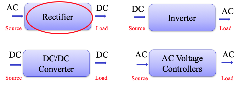
Rectification and Rectifier Circuits
Rectifiers with ability to control the magnitude of the DC voltage are described as controlled rectifiers
Rectifiers with no control over the voltage are called uncontrolled rectifiers.
Rectifiers can be fed from single phase or three phase AC supply.
Single phase rectifier circuits (Week 4)
Single phase uncontrolled half wave rectifier
Single phase controlled half wave rectifier
Single phase uncontrolled bridge circuits
Single phase half controlled bridge circuits
Single phase fully controlled bridge circuits
Three phase rectifier circuits (Week 5)
Three-phase uncontrolled half-wave circuit
Three phase fully-controlled half wave circuit
Three phase half-controlled half wave circuit
Three-phase uncontrolled full-wave bridge circuit
Three phase fully-controlled full-wave bridge circuit
Three phase half-controlled full-wave bridge circuit
Converter Operation (Week 6)
Regulation
Overlap -
Single phase rectifier circuits
Half wave rectifiers
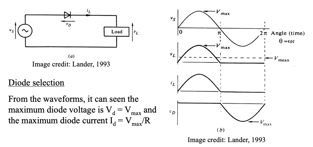
Uncontrolled half wave rectifier:
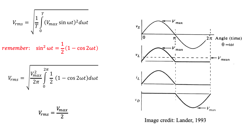
(a) Supplying a resistive loadSimplest and the most widely used rectifier circuit at low power levels. Output voltage and current of this rectifier are strongly influenced by the type of the load.
Uncontrolled half wave rectifier:
(b) Supplying a inductive loadAlmost all d.c. loads contain some inductance; the waveforms shown below are for an inductive load having the equivalent circuit shown.
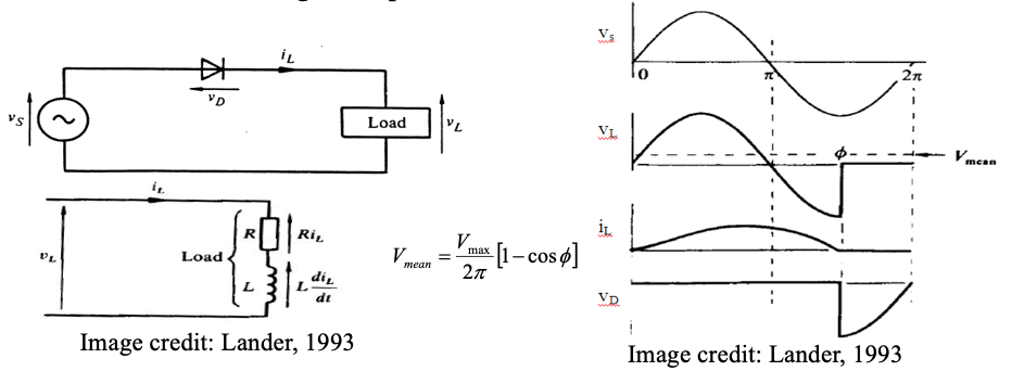
Current flow will commence directly the supply voltage goes positive, but the presence of the inductance will delay the current change, the current still flowing at the end of the half cycle, the diode remains on, and the load sees the negative supply voltage until the current drops to zero.
Thus output voltage will contain both positive and negative components.
-
Controlled half wave rectifier
The single-phase half-wave circuit can be controlled by replacing the diode by a thyristor as shown. The circuit also shows a commutating diode the purpose of which is twofold:-
● to prevent a negative load voltage
● to allow the thyristor to regain its blocking state at the voltage zero by transferring (commutating) the load current away from the thyristor.
The thyristor will start to conduct when its voltage vT is positive and receives a gate firing pulse (ig).
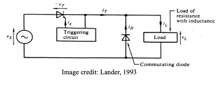
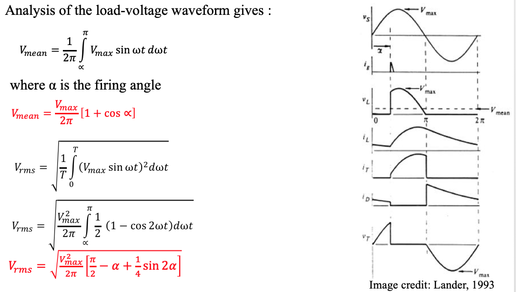
The waveforms assume the presence of a commutating diode.
Without the commutating diode, the waveforms would be similar to those of uncontrolled half wave rectifier supplying an inductive load with the exception of a delayed start
Example
The single-phase half-wave circuit with a commutating diode as shown in Figure is used to supply a heavily inductive load of up to 15A from a 240 V a.c. supply. Determine the mean load voltage for firing delay angles of 0°,45°, 90°, 135°, and 180°, neglecting the thyristor and diode volt-drops.
Specify the required rating of the thyristor and diode.
Solution

Thyristor rating:
Peak forward (or reverse) voltage = Vmax = 240√2 = 340 V
The thyristor will conduct for a maximum duration (half cycle) at α = 0° and, if level current is assumed, then using two equal time intervals the r.m.s current rating can be calculated as: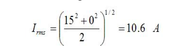
Diode rating:
PRV = Vmax= 340V. As the firing delay approaches 180°, the diode will conduct for almost the whole cycle; hence the required current rating would be 15A. -
Full wave bridge rectifiers
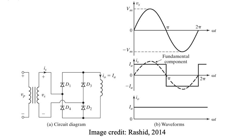
Uncontrolled full wave bridge rectifier
Variety of bridge rectifier circuit layouts are shown.
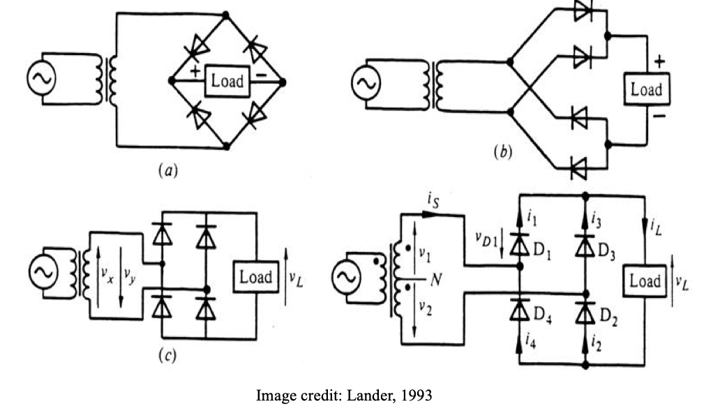
(a) Supplying resistive load
One layout of bridge rectifier circuit with waveforms are shown.
Example
Calculate the ripple factor for F.W. Uncontrolled circuit? Compare this to the H.W. circuit
Solution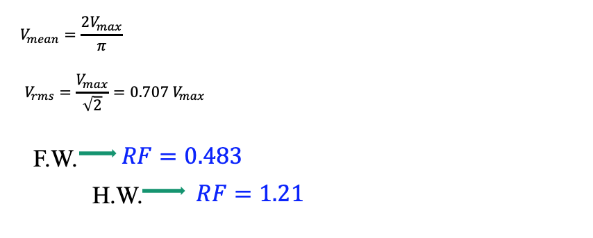
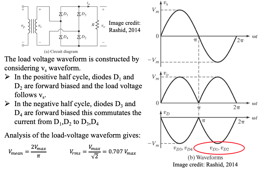
(a) Supplying inductive load
With highly inductive load, level current flows in load:
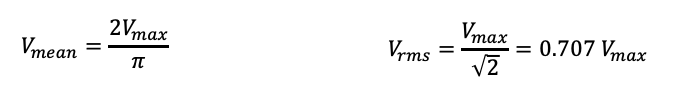
Analysis of the load-voltage waveform gives the same mean and r.m.s voltages:
Example:
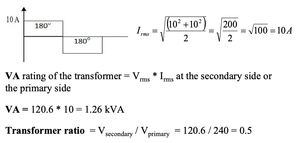
A single-phase diode bridge supplies 107 V, 10 A to a highly inductive load. The diode bridge is connected to a single phase a.c. supply via a transformer. Assuming that the diode has a volt-drop of 0.8 V, calculate:
(i) the r.m.s voltage and current at the transformer secondary side and
(ii) the transformer ratio and rating, if the primary side is connected to a 240-V typical home supply.
Solution
Find RMS voltage on the secondary of the transformer: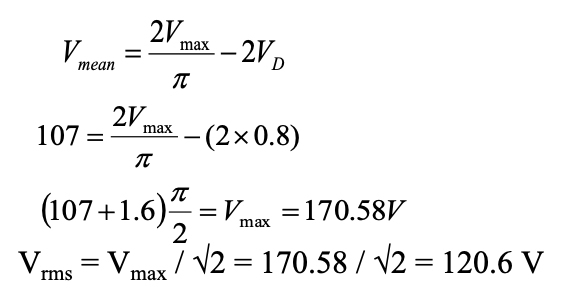
For the highly inductive load, the current will be:
-
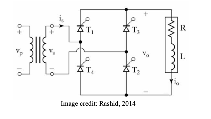
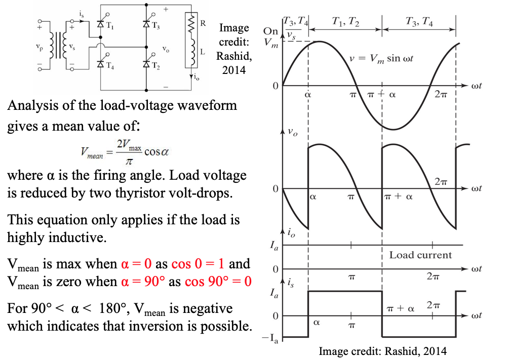
Fully controlled full wave bridge rectifier
The fully-controlled circuit shown has thyristors in place of the diodes. Conduction does not take place until the thyristors are fired. For current to flow, thyristors Tl and T2 must be fired together, as must thyristors T3 and T4 in the next half cycle.
-
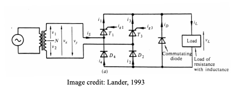
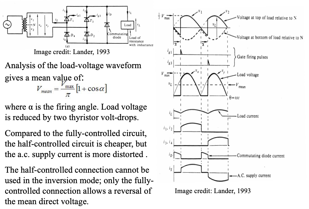
Half controlled full wave bridge rectifier
In the half-controlled circuit two of the diodes in the uncontrolled circuit are replaced with thyristors as shown. When the supply half cycle is positive and when thyristor T1 is triggered the load current flows through T1, the load and D2.
Thyristor T1 is turned off when the supply voltage enters the negative half cycle. As the load is inductive the load current still flows and it will free-wheel around the commutating diode and load loop. When Thyristor T3 is triggered during the negative half cycle, the load current flows through T3, the load and D4. The diode provides the free-wheeling path for the load current when T3 switches off.
-
Summary of Full wave bridge rectifier circuit
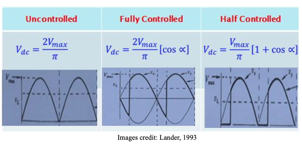
Summary of Full wave bridge rectifier circuit
- Identifying single phase rectifier circuit topologies
- Half wave uncontrolled
- Half wave controlled
- Full wave uncontrolled
- Full wave fully controlled
- Full wave half controlled- Circuit parameters (Mean/r.m.s voltage, RF, FF, diode/thyristor ratings)
- Differentiate impacts of inductive and resistive loads
- Identifying single phase rectifier circuit topologies
-
Check your understanding by answering the following:
- What is the main difference between diode and thyristor rectifiers?
- Draw the circuit diagram for:
(a) Half wave uncontrolled rectifier
(b) Half wave controlled rectifier
(c) Full wave uncontrolled bridge rectifier
(d) Full wave fully-controlled bridge rectifier
(e) Full wave half-controlled bridge rectifier
- Sketch waveforms for load voltage, load current and diode voltages in:
(a) Half wave uncontrolled rectifier with resistive load
(b) Full wave uncontrolled rectifier with resistive load
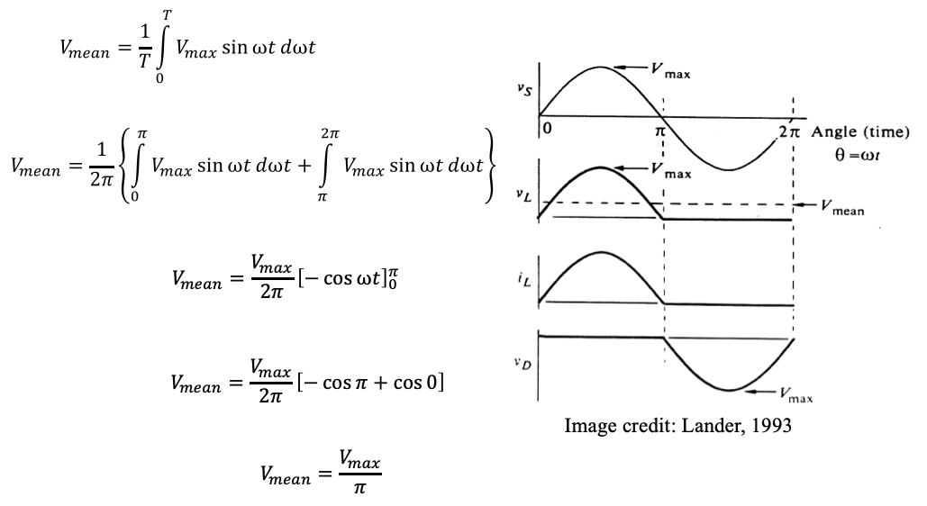
- Derive an expression for mean output voltage for:
(a) Half wave uncontrolled rectifier with resistive load
(b) Half wave controlled rectifier with commutating diode
(c) Full wave uncontrolled rectifier with resistive load
- With the aid of simple sketch waveforms:
(a) Discuss the impact that an inductive load has on the operation of single phase half wave diode rectifier circuit.
(b) Explain how the impact of the inductive load on the rectifier circuit can be mitigated.
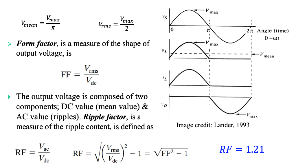
- What is the difference between form factor and ripple factor of a waveform?
- Is a full wave rectifier expected to have a higher ripple factor than half wave rectifier or vice versa? Comment on your answer.
- Given any drawing of a converter circuit in this lecture, identify the name of the converter.
- Given a set of waveforms for any converter in this lecture, identify which converter they belong to.