-
- Objectives
- to explain the role of design patterns in software design
- to discuss the distinction between architectural design patterns and detailed design patterns
- to describe a set of commonly used architectural design patterns.
-
Introduction
A Design Pattern is an existing design solution to a common problem that captures experience and good practice in a form that can be reused. All patterns are guided by a small number of software design principles (see Chapter 2 Table 1). A design pattern is normally not a complete solution that can be transformed directly into code. It is a description or template for how to solve a problem that can be used in many different situations, an abstract representation that can be implemented in different ways. Such a description simplifies communication between software practitioners. However you will find efforts available on the Internet to provide code templates in specific languages for some patterns. Patterns are not essential in the development of software solutions but are valuable sources of advice and guidance.
Patterns were introduced by Christopher Alexander in the field of building architecture, where he documented reusable architectural proposals for producing good quality building designs. In 1995 Gamma et al. [1] (the “Gang of Four” – GoF) adapted the concept of patterns for software development and catalogued 23 detailed design patterns aimed at meeting some commonly-recurring object-oriented design needs, albeit at the level objects (component/ subsystem interactions). Simplified explanations of these 23 design patterns are presented in [2]. Since then many software design patterns, pattern types and pattern catalogues have emerged, having emanated from different software development communities building different types of system using different methods, languages and tools, which also explains different naming conventions.
Pattern Types

Figure 1: Impact of Pattern Types Figure 1 shows a range of pattern types set against two axes: the extent to which they are specific to a particular application domain, and the level of design abstraction they are addressing, where low is close to code and high is close to requirements. Some of these patterns are domain independent and can in principle be used for any type of system. Some have been developed for a particular application domain e.g. enterprise design patterns [3] (where an enterprise is a large information transactional system such as an airline reservation system); game design patterns [4]. Some have been developed for different stages of the software development process e.g. requirements patterns [5], architectural patterns (see Appendix 1), runtime allocation patterns (see Appendix 1). The Gang of Four design patterns [1] are considered as detailed design patterns. The enterprise design patterns in [3] straddle architectural patterns and detailed design patterns. Sometimes one pattern uses some combination of other patterns. We will see later that one way of implementing a Model-View-Controller architectural pattern is to use an Observer pattern and a Strategy pattern which are detailed design patterns (Chapter 4).
In the discussion above what we have been referring to are Logical patterns i.e. the configuration of principal abstractions you will code up. These are distinguished from Physical patterns i.e. the configuration of physical computers that this code will be located on. The geographical location of physical hardware, its ownership, preferred supplier, and available budget are all factors that affect the choice of physical pattern. These in turn can affect the logical pattern. For example, nowadays most computer-based systems are distributed and use a Client-Server or Service-Oriented or Microservices logical pattern but normally all the Clients and the Server are all on different physical machines.
Benefits
- The benefits of patterns are that they:
- Identify and document proven design experience of recurring solutions and their trade-offs which can be used for similar problems in a given context
- Provide a common vocabulary for design and architecture
- Clarify and document existing architectures
- Move design forward and influence design decisions.
Limitations
How valuable any one pattern is will depend on the quality of the pattern documentation making clear the specific design problem and the application domain context for which it has been written. Pattern selection should be based on similarities between the available patterns and the specific design problem to be addressed within the specific application domain context. However with so many patterns available, so many different styles of documenting and cataloguing patterns and so much variation in pattern documentation quality, search and find is a very difficult task and remains an outstanding research challenge. For example, in [9] the authors propose a software architecture pattern selection model which can be followed in designing IoT systems. Often the use of an appropriate pattern relies heavily on the experience of a designer or design team. This partly becuase pattern descriptions do not come with any example implementations which can be a source of frustration for some programmers.
📹 Watch this personal perspective on software architecture process (45 mins) by Simon Brown on Architecture vs Code: Software Architecture vs. Code
💡 Exercise: Which of his views would you question and challenge ?
1A Pattern Language: Town, Buildings, Construction. Alexander, C., Ishikawa, S., Silverstein, M., Oxford University Press, New York, 1977.
-
Architectural Patterns
An architectural pattern describes:
- i. the strategic overarching structure of all or a significant aspect of a system using
- a set of components that perform a function required by the system
- a set of connectors that enable communication, coordination and cooperation among components
ii. constraints that affect how components behave and how they can be connected
iii. a semantic model that enables a designer to understand the overall properties of a system by analysing the known properties of its constituent parts.Detailed design patterns are:
i. narrower in scope
ii. often used to implement architectural patterns
iii. sometimes actually impose a rule on the architecture, describing how the software will handle some aspect of its functionality at the infrastructure level e.g. concurrency
iv. tend to address specific behavioural issues within the context of the architecture e.g. how to handle synchronisation or interrupts.Using Patterns
- In practice, designers often sketch out a first design regardless of patterns and then, using their prior knowledge and experience recognise existing patterns in their first design and incorporate these into later drafts, albeit often adapting them. One challenge using existing patterns is to understand their description and domain context for which they were envisaged to be deployed. Different pattern authors use different templates and notations to describe pattern details whilst broadly adhering to the following sections:
- Pattern name
- Pattern problem (that it is designed to address)
- Pattern solution (that describes the solution components and their relationships)
- Pattern consequences (the results and trade-offs of using the pattern)
- Pattern implementation advice.
- However, even commonly accepted and used patterns (see Appendix 1) can be difficult to agree on. This is because across different organisations, different software development communities and different individuals:
- use different names for the same pattern
- include ambiguity into their descriptions allowing different interpretations to be placed upon them
- have different level of details in the description
- devise a new pattern as a simple variation on a previous pattern but do not say this.
📹 Introduction to Patterns by Professor Doug Schmidt at Vanderbilt University (36 mins)
An Overview of PatternsOne of the criticisms of patterns is that they are not on any formal footing and it is difficult to combine patterns with any sort of rigour. Work continues to explore the theme of general and domain-specific pattern languages to address these issues [6, 7]. A 2014 study [8] of software developers revealed that key factors in encouraging the use of patterns were clear explanations of: the problem being solved and their contextual assumptions and hence their ability to integrate with existing systems; implementation issues; quality attributes possessed by software patterns, and signposts to other relevant documentation.
The architecture of a software system is rarely able to be described by a single architectural pattern. Consequently often a pattern is used as a default starting point for different types of system and is modified as design proceeds. This will be because in the eyes of the architect that approach to design seems to be the best fit to the specific requirements of the problem at hand. For example if you are building a public facing Web application, you can separate your presentation logic from your business logic from your data access logic using a Layered architectural pattern. On the presentation layer, you may decide to use a presentation pattern, such as Model-View-Controller (MVC). You might also choose a Service Oriented Architecture pattern between your Web server and Application server.
Many factors will influence the architectural patterns you choose. These factors include the capacity of your organization for design and implementation; the capabilities and experience of your developers; and your infrastructure and organizational constraints. Some patterns are deliberately designed for specific types of system. For example, in [3], where the set of patterns are for enterprise information systems, the underlying assumption is that the presentation and business logic will be developed using an object-oriented approach and the database formed from relational tables and accessed using SQL Scripts, hence many of the patterns in the book are bridges between object-oriented and relational data structures.
Appendix 1 sets out the detail of a small catalogue of commonly used architectural patterns. Draw upon them and combine them for any systems you will build. Each description sets out the problem context, problem solution, the strengths and weaknesses of the pattern, an example problem and solution, and a short discussion on some implementation issues. These descriptions capture what the pattern is like in its “pure” state. In practice patterns are often modified to suit the context at hand, sometimes to the extent that the original pattern is no longer recognisable. There are many other sources of information about these patterns and you should try to understand more than one description because each explanation will be subtly different.
- Appendix 1 presents details about:
- Layered
- Client Server
- Peer to Peer
- Model View Controller
- N-Tier aka 3-Tier, State-Logic-Display
- Repository aka Shared Data, Data-Centred, Blackboard, Rule-Based, Microkernel
- Pipe and Filter aka Data Flow
- Event-Based aka Sense-Compute-Control
- Publish-Subscribe
- Service-Oriented Architecture
- Microservices
Table 1 shows how some of them can be organized by key focus area.
Table 1: Architectural Pattern Categories by Function Category Architecture styles Communication Service-Oriented Architecture, Microservices, Event-based, Publish-Subscribe Deployment N-Tier Structure Layered Architecture, Client-Server, Pipe-and-Filter Presentational MVC 📖 Ch 6, 17, 21 of Sommerville, I, Software Engineering, 10th edition, Pearson 2016.
-
Anti-Patterns
AntiPatterns, like their design pattern counterparts, define an industry vocabulary for the common defective processes and implementations within organisations. An AntiPattern is a literary form that describes a commonly occurring solution to a problem that generates decidedly negative consequences. The AntiPattern may be the result of a manager or developer not knowing any better, not having sufficient knowledge or experience in solving a particular type of problem, or having applied a perfectly good pattern in the wrong context. AntiPatterns provide support for recognising recurring problems in software development and offer a remedy for the most common predicaments.
-
References
1. Design Patterns: Elements of Reusable Object-Oriented Software, Gamma, E., Helm, R., Johnson, R., Vlissides, J., Pearson, 1995.
2. Design Patterns Explained Simply, Shvets, A., www.sourcemaking.com
3. Patterns of Enterprise Application Architecture, Fowler, M., Addison-Wesley, 2003
4. Game design patterns. Bjork, S., Lundgren, S., Holopainen, J., in: Lecture Notes of the Game Design track of Game Developers Conference, March 4–8, San Jose,CA, USA, 2003
5. Software Requirements Patterns, Franch, X., Software Engineering (ICSE), 2013 35th International Conference, 18-26 May 2013, doi 10.1109/ICSE.2013.6606758
6. Pattern-Oriented Software Architecture: On Patterns and Pattern Languages, Buschmann, F., Henney, K, Schmidt, D.C., Wiley, 2007
7. Survey On Software Design-Pattern Specification Languages, S Khwaja, M Alshayeb, ACM Computing Surveys, 49, 1, Article 21, June 2016
8. Questionnaire Report on Matters Relating to Software Patterns, Almari, H, Broughton, C, 5th International Conference on Information Science and Applications (ICISA), 6-9 May 2014, Seoul, Korea, ISSN: 2162-9048, pp1-5.
9. Software Architecture Pattern Selection Model for Internet Of Things Based Systems, J M Pramod, M Prasanna, IET Software., 2018, Vol. 12 Iss. 5, pp. 390-396
-
Layered Pattern
The Layered pattern is useful for an application that needs to partition functionality into different cohesive layers (e.g. to reduce security risk, to separate workloads) such that a higher layer can request information from a lower layer but a lower layer can only send information (e.g. status) up to a higher layer.Problem Context:📷 Figure A2 shows a typical generic layered architecture for a generic system in which each layer has cohesive functionality. The default setting is that a layer above can only use the layer immediately below. A layer below provides services to the layer above it so the lowest-level layers represent core services that are likely to be used throughout the system. Each layer can only communicate with the layers immediately above and below it. A set of layers in which any layer can access any other layer is not a Layered pattern as intended and has few advantages. Exceptionally, a higher layer can use the services of a layer below the one immediately below it, but this needs to be made transparent in text and any notation used and the rationale documented clearly.Problem Solution:📷 Figure A3 shows a typical Enterprise Information System (EIS) conceived as having three layers in which the presentation layer is separated from the Business Logic of the application which in turn is separated from the Data Access Layer. 📷 Figure A4 shows an example digital learning EIS. The Layered pattern is also useful when having to provide new facilities on top of existing systems e.g. many financial services systems continue to rely on systems that were written 40-50 years ago in COBOL but no-one is sure how they work(!), replacing them is too costly, and changing them is too risky. So new service provision is written on top of the existing system by building a “wrapper” layer and only it can access the old system.Example Problem:✓ Layers may be easy to understand
✓ Layers are loosely coupled so that they can be developed, maintained and exchanged separately without rewriting other layers so long as the interface is maintained.
✓ Additional facilities (e.g. authentication) can be provided in each layer to increase the dependability of the system
✘ In practice, providing a clean separation between layers is often difficult and a high-level layer may have to interact directly with lower-level layers rather than through the layer immediately below it.
✘ Adding a new functionality might affect every layer.
✘ As layer numbers increase performance can become a problem because of multiple levels of translation and interpretation are required to process a service request.Consequences:Typically procedure calls are made and parameters are passed between layers. See also Appendix 1 Section 5 N-Tier Pattern.Implementation:Microsoft – Layered Application Guidelines
🔗 Chapter 5: Layered Application Guidelines
🔗 Sun Java Center - J2EE PatternsX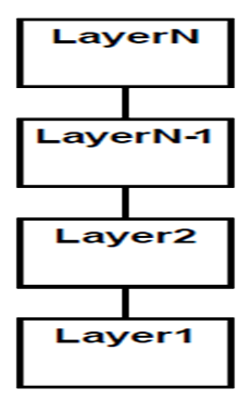
Figure A2: Layered Architecture Pattern X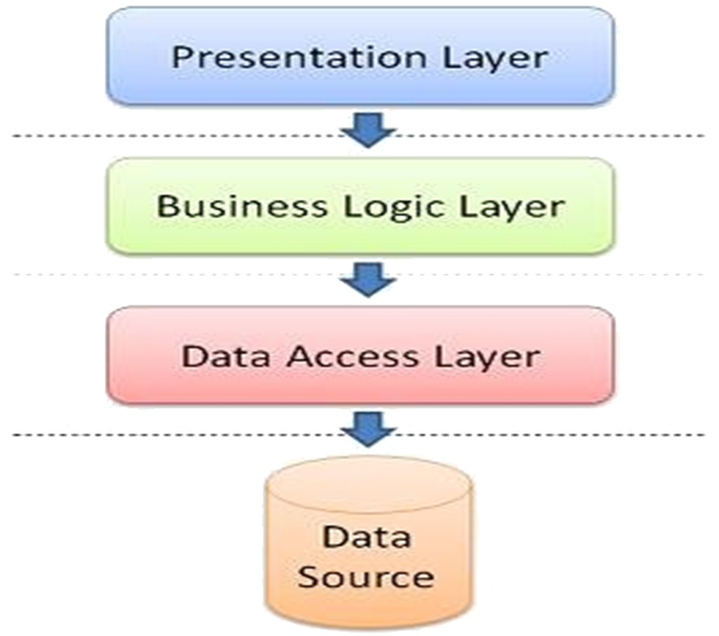
Figure A3: Typical Enterprise Information System X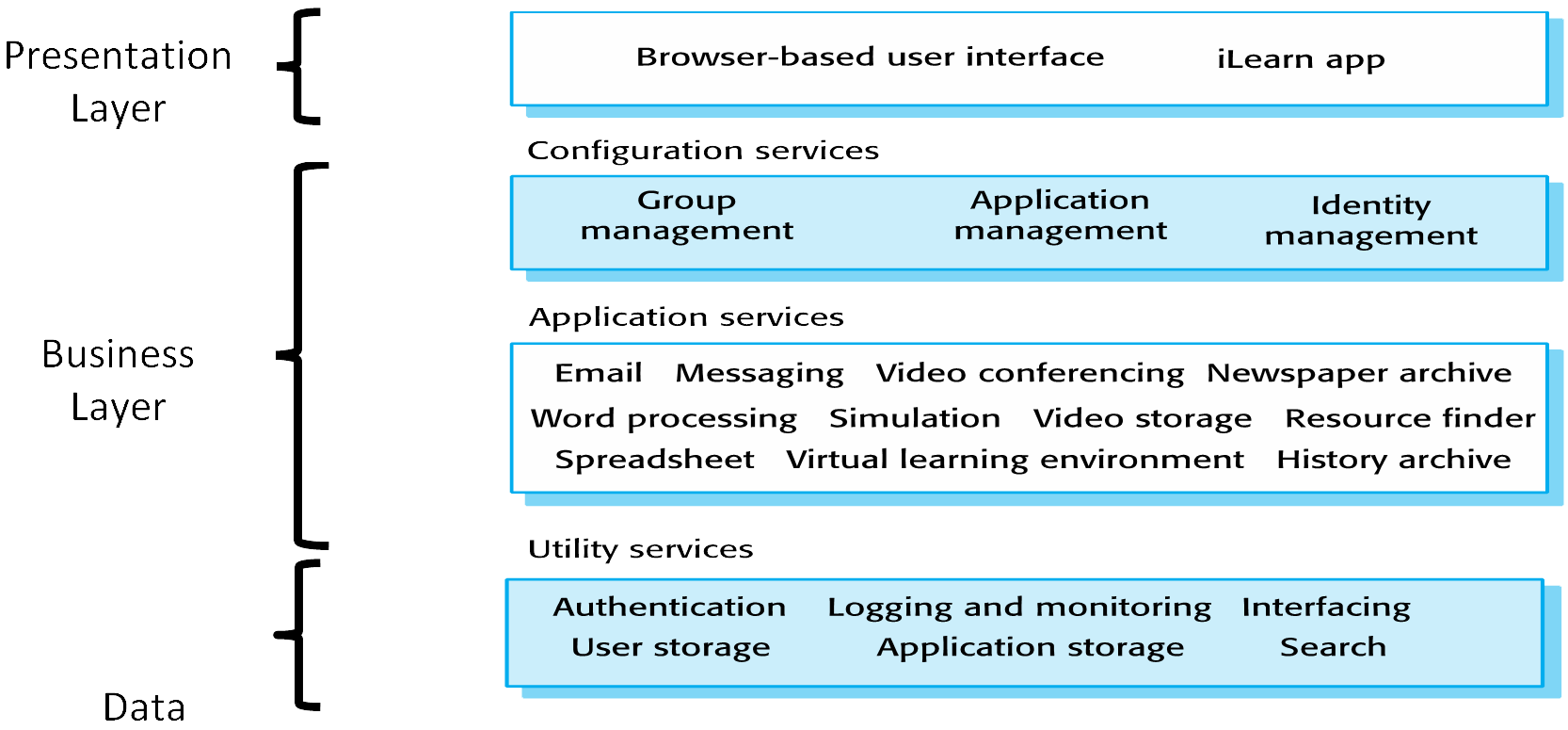
Figure A4: A Digital Learning System represented as a Layered Pattern2 2Taken from Sommerville, I Software Engineering
-
Client-Server Pattern
The Client-Server pattern is useful to describe an application in which we want to make available a shared set of resources and services accessible to a large number of clients who may be distributed across from a range of locations e.g. printing or data. It is interpreted to be more of a physical deployment pattern. At the logical level for Enterprise Information Systems each client-server relationship will be conceived to separate the presentation-business-logic logical layers.Problem Context:At its simplest this pattern can be understood as a two-layer Layered pattern. 📷 Figure A5 shows the typical client server architecture. A Client makes a resource request to a Server for services needed. The Server replies to the request and offers the service if it is able. In high security systems, servers will also check whether a Client has permission to request the service. Some components can be both Clients and Servers.Problem Solution:📷 Figure A6 shows an ATM Enterprise Information System.Example Problem:✓ Servers can be distributed across a network so if a part of the network fails not all servers fail, and this risk is reduced if duplicate servers are introduced.
✓ General functionality can be available to all clients and does not need to be implemented by all services.
✓ Easy to add new Clients and new services to the system
✘ Each service is a single point of failure and is susceptible to denial of service attacks or server failure
✘ Performance can be unpredictable because it depends on the network as well as the system management problems may be arise if servers are owned by different organisations.
Consequences:Clients are connected to servers through request/reply connectors. Clients have ports that describe the services they require. They need to know the identity of each server. Servers have to be available when clients need to use them. Servers also have ports describing what services they provide and how many Clients they can provide to at any one time. Server components can be clients to other servers. A server component perpetually listens for requests from client components (often implemented as remote procedure calls). When a request is received, the server processes the request, and then sends a response back to the client (the key issue is “when?” either immediately by way of a holding response or when request is processed). Servers may be further classified as stateless or stateful, but are usually stateless. A stateless request means a server does not retain transaction “session” information about each transaction with a client once the transaction ends. A stateful request means a server does keep record of each transaction session which often occurs in systems that allow a client to make a composite request consisting of multiple requests and the status of processing the composite request is required. In practice clients are referred to as “thick” or “thin” depending on the extent of data processing they do beyond user interface functions. Thick clients are very customizable and a user has more control over what programs are installed and their specific system 🔗 configuration. On the other hand, thin clients are more easily managed centrally, are easier to protect from security risks, and offer lower maintenance and licensing costs. Two other key factors affect the choice of thick or thin client in a system: (i) the extent to which the client needs to process the data from the services offered by the servers to add value to the user (ii) the quality (performance, reliability, security) of the network connections between the clients and the server (i.e. risk management).Implementation:Sidebar: A Web server is a program that uses HTTP (Hypertext Transfer Protocol) to serve the files that form Web pages to users, in response to their requests, which are forwarded by their computers' HTTP clients. Dedicated computers and appliances may be referred to as Web servers as well. The process is an example of the client/server model. All computers that host Web sites must have Web server programs e.g. Apache, Microsoft's Internet Information Server (IIS), Google Web Server (GWS). Web servers often come as part of a larger package of Internet- and intranet-related programs for serving email, downloading requests for File Transfer Protocol (FTP) files, and building and publishing Web pages. Considerations choosing a Web server include how well it works with the operating system, other servers, its server-side programming capability, security characteristics, and the publishing, search engine and site building tools that come with it.
When you type in a URL the web browser on the Client translates it into an IP Address which it uses to connect to the server machine. The web browser forms a connection to the server at that IP address on port 80. Following the HTTP protocol, the browser sends a GET request to the server, asking for the file "http://www.howstuffworks.com/web-server.htm." The server then sent the HTML text for the Web page to the browser. (Cookies may also be sent from server to browser in the header for the page.) The browser read the HTML tags and formatted the page onto your screen.
X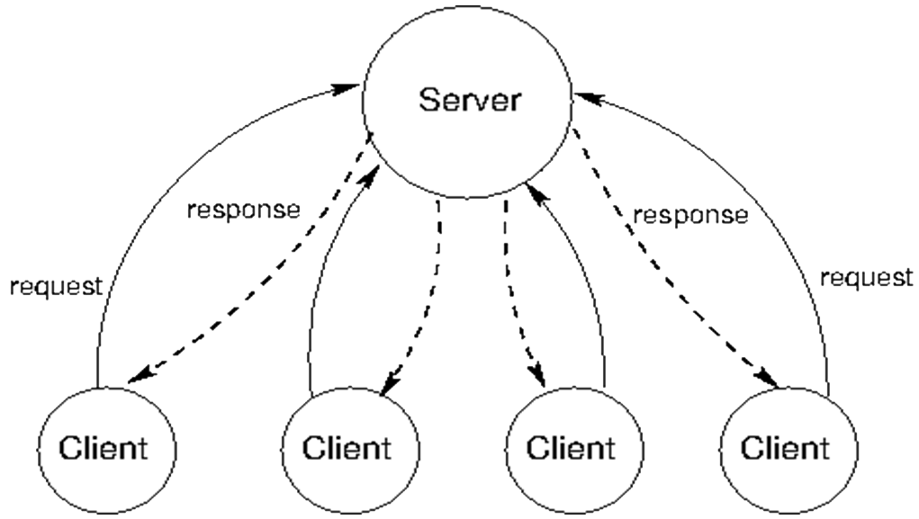
Figure A5: Client-Server Architecture X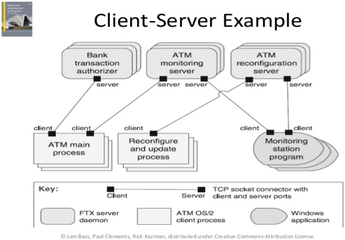
Figure A6: Banking Automated Teller Machine (ATM) Multi-Client Multi-Server Example -
Peer-to-Peer (P2P) Pattern
The P2P patterns is useful when distributed computation entities are needed to co-operate and collaborate to provide a service to a community of users e.g. file sharing, “Voice over IP (VoIP)”, routing; or when a large computationally intensive problem can be divided into sub-problems that can be done separately and in parallel.Problem Context:📷 Figure A7 shows a peer-to-peer architecture. Peers can act as functional processors and/or communication switches. All components are peers and equal in importance i.e. any component can interact with any other component by requesting its services. Communication between peers is a request/reply i.e. in client-server terms each peer component can be both a client and server.Problem Solution:Examples include BitTorrent (file sharing, see Sidebar: BitTorrent and 📷 Figure A8), Bitcoin (payment exchange, see Sidebar: Distributed Ledgers). Until 2016 Skype was perhaps the pre-eminent P2P application most people were familiar with but its owner (Microsoft) has changed it to a Client-Server architecture, principally for security and performance reasons . Examples of a computationally intensive problem using P2p are weather forecasting and multi-molecule analysis of the impact of a proposed medication during drug discovery.Example Problem:✓ Scales well because peers can be added and removed with no significant impact on the network traversal algorithms
✓ Efficient use of network capacity
✘ The significant weakness in P2P is that the distribution of control makes managing security, data consistency, data and service availability difficult. Often the lack of centralised management means that attackers can set up malicious nodes that deliver spam and malware to legitimate P2P users. One response is to make greater use of encryption. For example, the Payment Card Industry (PCI) has established a PCI Security Standards Council that has released a set of standards for third party providers to offer P2P Encryption (P2PE) programme.Consequences:Peers first connect to the P2P network and then discover other peers they can interact with. In principle peers can be added and removed without necessarily having a significant impact on the network or the application using the network. Absence of centralisation makes resource discovery an important issue. In pure P2P a request for information is sent to each peer. Sending the request to each peer and collating all the replies takes time and depends on the size of the network and the networking algorithm that traverses each peer. So in hybrid applications often peers are grouped into “localities” and some individual peers are designated as “special” and have routing, indexing or searching capabilities. Napster for example had a centralised server for indexing music and locating peers.Implementation:Sidebar: BitTorrent is P2P filesharing system. A group of computers (“swarm”) downloading and uploading the same “torrent” transfer data between each other without the need for a central server. Traditionally, a computer joins a swarm by loading a .torrent file into a BitTorrent client. The BitTorrent client contacts a Tracker specified in the .torrent file. The Tracker is a special server that keeps track of the connected computers, and shares their IP addresses with other clients in the swarm, allowing them to connect to each other. Once connected, a BitTorrent client downloads bits of the files in the torrent in small pieces, downloading all the data it can get. Once the client has some data, it can begin to upload that data to other clients in the swarm. Users downloading from a swarm are commonly referred to as Leechers or Peers. Users that remain connected to a swarm even after they’ve downloaded the complete file, contributing more of their upload bandwidth so other people can continue to download the file, are referred to as Seeders. For a torrent to be downloadable, one seeder – who has a complete copy of all the files in the torrent – must initially join the swarm so other users can download the data. If a torrent has no seeders, it won’t be possible to download – no connected user has the complete file.
📖 Read Ch11, section 11.3.2 Taylor, R et al, Software Architecture, Foundations, Theory & Practice, Wiley 2009
📹 For more on BitTorrent look at BitTorrent as Fast As Possible
Sidebar: Distributed Ledgers When money is transferred, each party involved e.g. retail banks, clearing banks marks the transaction in its ledger. Such record-keeping and reconciliation is in effect duplication. The inefficiency is exaggerated and most acute for global payments, since currency exchanges, time zone differences, cut-off times and other complexities can add days of delay. A distributed ledger is a tamperproof sequence of data that can be read and augmented by everyone. Directly connecting counterparties via a shared ledger would enable a global peer-to-peer (P2P) wholesale payments system. Payments could happen nearly instantly from and to anywhere in any currency. An immediately visible payment trail could simplify track and trace. Beyond transaction details, enriched data could be immutably linked to a transaction to allow easier, more accurate auditing of supporting documentation for a payment. Companies could gain anytime, anywhere, near-instant global access to their funds and related information. Cash could be in continual motion to meet a company’s working capital and liquidity needs worldwide. This is increasingly important as liquidity markets demand more efficient cash management. Blockchain Technology is about designs, implementations and tools to support the construction and maintenance of distributed ledgers.
🔗 What is blockchain? A primer on distributed ledger technology
3🔗 https://www.lifewire.com/skype-changes-from-p2p-3426522
X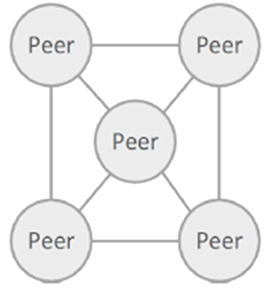
Figure A7: Peer-to-Peer Pattern X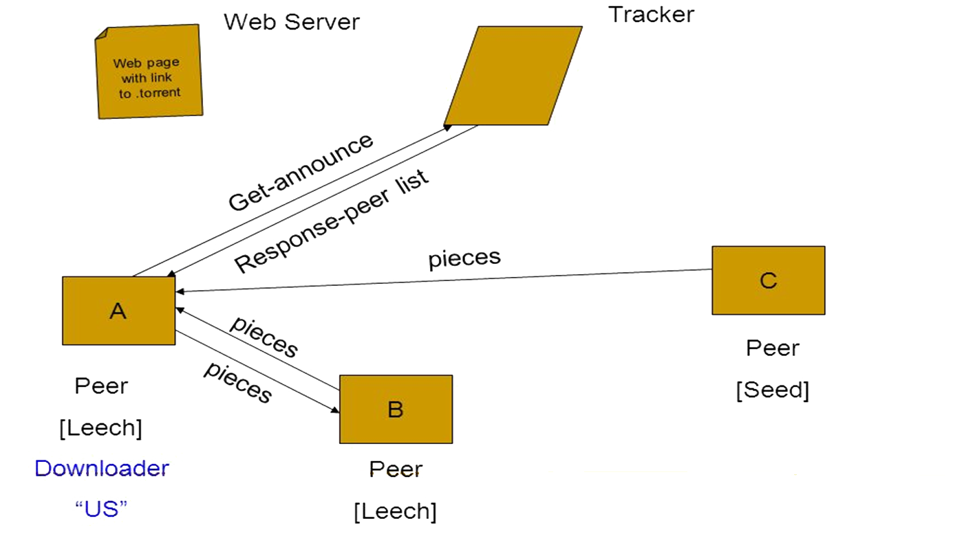
Figure A8: BitTorrent Architecture -
Model-View-Controller (MVC) Pattern
The MVC pattern is useful for an application that involves much user interaction in order to manipulate and display a lot of data e.g. for an enterprise information system (see Chapter 1 Table 1) in which the problem is how to create a design that makes it easy to change the user interface without affecting the underlying data structures and change the underlying data structures without necessarily changing the user interface.Problem Context:MVC is often used in a Layered architecture (or N-tier architecture) for the Presentation or User Services layer (tier), and in which the domain objects used in the Model would be the objects from the business layer. MVC can also be used for the user interface of an application which is not N-tier e.g. a calculator with no underlying persistence, and therefore no data access layer. It has been a dominant influence in the design of graphical user interfaces. See 📷 Figure A9. A Model subsystem contains business data and data manipulation rules. A View subsystem displays some portion of the underlying data and interacts with the user. A Controller mediates between the Model and the View and manages the notifications of state changes. The Controller subsystem accepts a request from the user, invokes processing on the Model subsystem and decides which of the graphical user interfaces (GUIs) in the View subsystem to display. The View queries the Model and might pass user interafce events to the Controller.Problem Solution:A sudden upswing/downswing (e.g. +/-5%) in share price of a large company e.g. Microsoft can have a large impact on the value of stock market indices e.g. FTSE-100, NASDAQ, Dow-Jones Index, all of which can trigger a run in buying or selling of shares in a range of companies. So Financial Traders constantly have several charts displayed simultaneously of different share groups and their real-time share price movements. Each chart/graph is a separate view and each view can be dynamically updated as the model of share prices change. The MVC pattern is widely used in user interface libraries e.g. Java Swing classes, Microsoft’s ASP.Net, Adobe Flex. 📷 Figure A10 shows an interface for a hotel reservation system.Example Problem:✓ Easy to change the implementations of Model, View or Controller without affecting the other subsystems
✘ Dividing the subsystem increases communication overhead which can affect performance (clearly important in time-critical applications), so sometimes the View and Controller subsystems are merged.Consequences:The MVC components are connected to each other via a notification e.g. callbacks that contain state updates. A change in a Model needs to be communicated to the Views so that they may be updated. An external event e.g. a user input, must be communicated to the Controller, which may update the View and/or the Model. Notifications push or pull. Implementing an MVC can be achieved by using different Detailed Design patterns (see Ch. 4). The Controller should be as small as possible and the Model should do all it can without handling the HTTP requests or output formatting details. One problem with having the View and Controller connecting to the Model is that changing the Model’s public API means you also have to adapt the Controller and Views that act on it. Changing the Controller is often straightforward, changing several Views is not. A Document Object Model manipulation library can make building webpages much easier. However, these libraries can sometimes be less effective when used to build web applications that have significant user interaction as well as needing to communicate with a backend server in real time. Without an MVC framework you may end up writing 🔗 messy, unstructured, unmaintainable and untestable code. You should consider utilizing an MVC framework if you’re building an application with a complexity of client-side processing that would make using JavaScript alone untenable and lead you to re-invent the functionality provided by an MVC framework. If you are just building an application that still has a lot of the heavy lifting on the server-side (i.e. view generation) but little on the client-side, an MVC framework is likely overkill and it will be better to use a simpler setup such as a DOM manipulation library with a few utility add-ons. In summary an MVC framework is often suitable when: 1. Your application needs an asynchronous connection to the backend
2. Your application has functionality that shouldn’t result in a full page reload (i.e. adding a comment to a post, infinite scrolling)
3. Much of the viewing or manipulation of data will be within the browser rather than on the server
4. The same data is being rendered in different ways on the page
5. Your application has many trivial interactions that modify data (buttons, switches)
Good examples of web applications that fulfil these criteria are 🔗 Google Docs, 🔗 Gmail or 🔗 Spotify.Implementation:6The Document Object Model (DOM) is an application programming interface (API) for HTML and XML documents. It defines the logical structure of documents and the way a document is accessed and manipulated.
X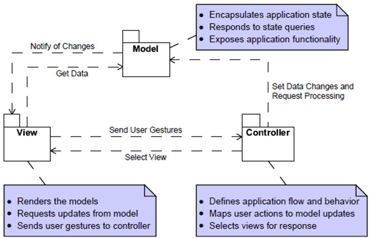
Figure A9: Model-View-Controller Pattern represented in UML X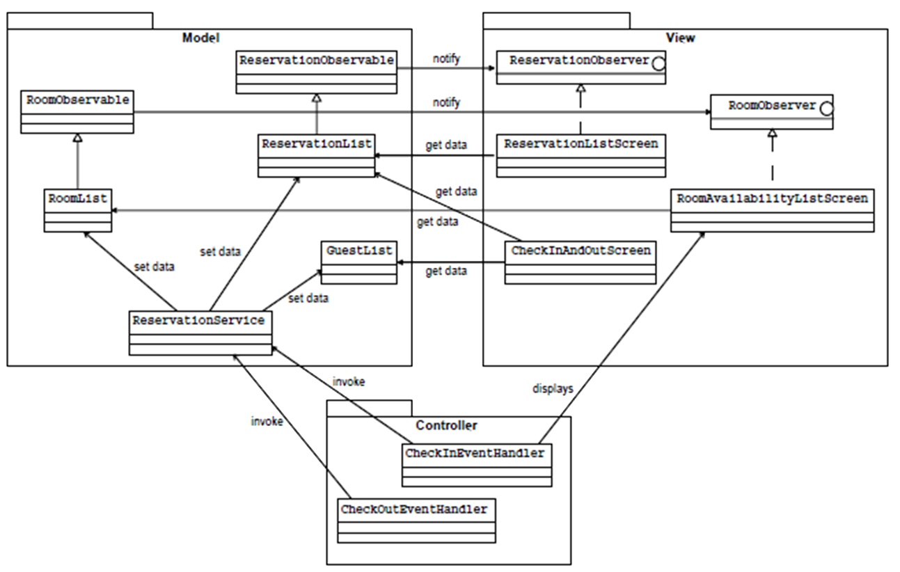
Figure A10: Hotel Reservation System represented using an MVC Pattern -
N-Tier (Multi-Tier) Pattern
This pattern is another variation on the Layered pattern but “Tiers” are often defined with an eye on the runtime environment, each tier running on an entirely different computer. For example different parts of the system infrastructure may belong to different organisations, or there may be qualitative reasons e.g. performance, security, reliability that make it a better option to do so. Many complex Enterprise Information Systems are often conceived and implemented as three distinct tiers: presentation (user interface / display); business logic (application logic); data (database / state).Problem Context:Tiers are logical groups of components though there can be a variety of criteria that govern what is “logical”. Normally components in one tier can communicate with either another component in the same tier or a component in an adjacent tier. Unlike Layers the type of communication can be two-way. For example, the presentation tier might be on a web server, which communicates over the network to the data access mechanism which might be a class library located in the business tier on a back-end application server. This in turn communicates to a database server again over the network. Separating application components into separate tiers increases the maintainability and scalability of the application. It does this by enabling easier adoption of new technologies that can be applied to a single tier without the requirement to redesign the whole solution. In addition, n-tier applications typically store sensitive information in the middle-tier, which maintains isolation from the presentation tier. (See Sidebar J2EE).Problem Solution:See 📷 Figure A11.Example Problem:✓ Easy to change the implementations of tiers without affecting the other tiers
✘ Dividing the subsystem increases communication overhead which can affect performance (clearly important in time-critical applications).Consequences:There are a number of different frameworks for building N-tier architectures.Implementation:📖 Microsoft – N-Tier Data Applications Overview
🔗 Visual Studio 2017
🔗 Visual Studio 2015The Oracle Hyperion Data Relationship Management, Fusion Edition N-tier product
🔗 Data Relationship Management N-tier ArchitectureN-Tier Architecture Explanations
📹 n-Tier Architecture Explained
📹 What Is n-Tier Architecture?Sidebar: J2EE
Sun Microsystems (now part of Oracle) designed Java EE to simplify application development in a thin client environment, 15 years ago. Java EE applications are hosted on application servers e.g. IBM's WebSphere, Oracle's GlassFish or Red Hat's WildFly server, all of which run either in the cloud or within a corporate data centre. While Java EE apps are hosted on the server side, examples of Java EE clients include an internet of things (IoT) device, smartphone, RESTful web service, standard web-based application, WebSocket or even microservices running in a Docker container. The J2EE Platform was constructed as 5 Tiers:
Client Tier
Web Browser
Java SwingPresentation Tier
e.g. JSP, ServletBusiness Tier
e.g. JavabeansIntegration Tier
e.g. JDBCResource Tier
Database
Legacy systemsThe Java EE architecture provides services that simplify the most common challenges facing developers when building modern applications, in many cases through APIs, thus making it easier to use popular design patterns and industry-accepted best practices. For example, one common challenge enterprise developers face is how to handle requests coming in from web-based clients. To simplify this challenge, Java EE provides the Servlet and JavaServer Pages (JSP) APIs, which provide methods for activities like finding out what a user typed into a text field in an online form or storing a cookie on a user's browser. Another common task is how to store and retrieve information in a database. To address this goal, Java EE provides the Java Persistence API (JPA,) which makes it easy to map data used within a program to information stored in the tables and rows of a database. Also, creating web services or highly scalable logic components is simplified through the use of the Enterprise JavaBeans (EJB) specification. All of these APIs are well tested, relatively easy for Java developers to learn and can greatly simplify some of the hardest parts of enterprise development.
X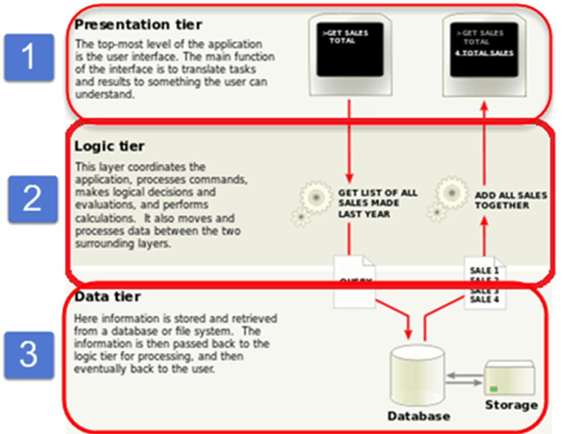
Figure A11: Sales Processing Information System -
Pipe and Filter Pattern
The Pipe and Filter is pattern is useful for a data processing application in which inputs are processed in separate stages to generate related outputs. At its simplest it is a Layered pattern in which the complexity of each Layer is simplified to some transformational data processing and communication is unidirectional.Problem Context:Streams of data passes successively through a connected set (a “pipe”) of transformation components (filters) with straightforward flexible interaction mechanisms so that they can be easily combined. Each filter is discrete and carries out one type of data transformation.Problem Solution:📷 Figure A12 shows a generic pipe and filter pattern diagram. 📷 Figure A13 shows an example of a pipe and filter system used for network message transmission processing invoices. Encryption-Decryption also uses a pipe and filter pattern.Example Problem:✓ Easy to understand and supports transformation reuse.
✓ Workflow style matches the structure of many business processes.
✓ Evolution by adding transformations is straightforward.
✓ Can be implemented as either a sequential or concurrent system.
✘ The format for data transfer has to be agreed upon between communicating transformations.
✘ Each transformation must parse its input and unparse its output to the agreed form. This increases system overhead and may mean that it is impossible to reuse functional transformations that use incompatible data structures
✘ Each pipe is a single point of failureConsequences:Pipes buffer data during communication so can execute asynchronously and concurrently. However the interfaces need to be clearly specified and understood several transformations, it is worth examining the efficiency improvement of some upstream filters operating concurrently with some downstream filters.Implementation:X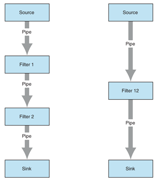
Figure A12: Pipe and Filter Pattern7 7https://msdn.microsoft.com/en-us/library/ff647419.aspx#despipesandfilters_context
X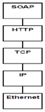
Figure A13: Network Message Stack -
Repository Pattern (“Microkernal” or “Plug-in” or “Data Store”)
The Repository pattern is useful for data-driven systems where the inclusion of data in the repository triggers an action or tool, or where sub-systems must exchange data and there is a large amount of data are to be shared, or in a typical enterprise resource information system where you want to separate the logic that retrieves the data and maps it to the entity model from the business logic that acts on the model. The business logic should be agnostic to the type of data that comprises the data source layer. See 🔗 The Repository Pattern It often consists of two types of architecture components: a core system and plug-in modules. Application logic is divided between independent plug-in modules and the basic core system, providing extensibility, flexibility, and isolation of application features and custom processing logic. The microkernel architecture pattern allows you to add additional application features as plug-ins to the core application, providing extensibility as well as feature separation and isolation. 📹 Patterns MicrokernelProblem Context:See 📷 Figure A14. All data is organised in a central repository. Interaction is dominated by the exchange of persistent data between multiple components and at least one shared repository. Exchange can be initiated by the components or the repository.Problem Solution:A Repository pattern is useful for implementing a product-based application packaged and made available for download in versions as a typical third-party product. Additional application features can be added as plug-ins to the core application, providing extensibility as well as feature separation and isolation. One example (📷 Figure A15) is an Integrated Development Environment (e.g. Visual Studio, Eclipse) where the components use a repository of system design information. Each software tool generates information, which is then available for other tools.Example Problem:✓ Components can be independent; changes made by one components can be propagated to all components.
✓ Components can be added/subtracted making it scalable to the problem needs
✓ All data can be managed consistently as it is done all in one place which is important for equality of opportunity, security, and privacy
✘ The repository is a single point of failure.
✘ Performance of data retrieval and communication is a concern as the repository grows and when back-up duplicate repositories are required for security.
✘ Distributing the repository across several computers may be difficult.Consequences:The repository needs to know which data accessor components are available and how to connect to them. One way to implement this is to use a component registry containing component name, remote access protocol details. In a “pure” pattern the data accessor component can only access data from the repository. Often in practice, the data accessor components can also access some data from other data accessor components that may hold their own databases (usually a smaller subset).Implementation:X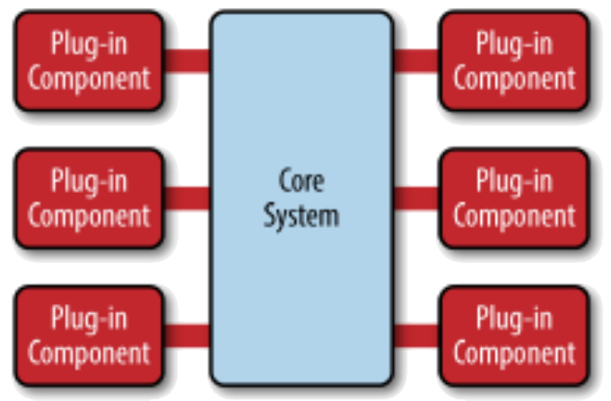
Figure A14: A Repository Architecture Pattern8 8Taken from Richards, M Software Engineering Patterns
X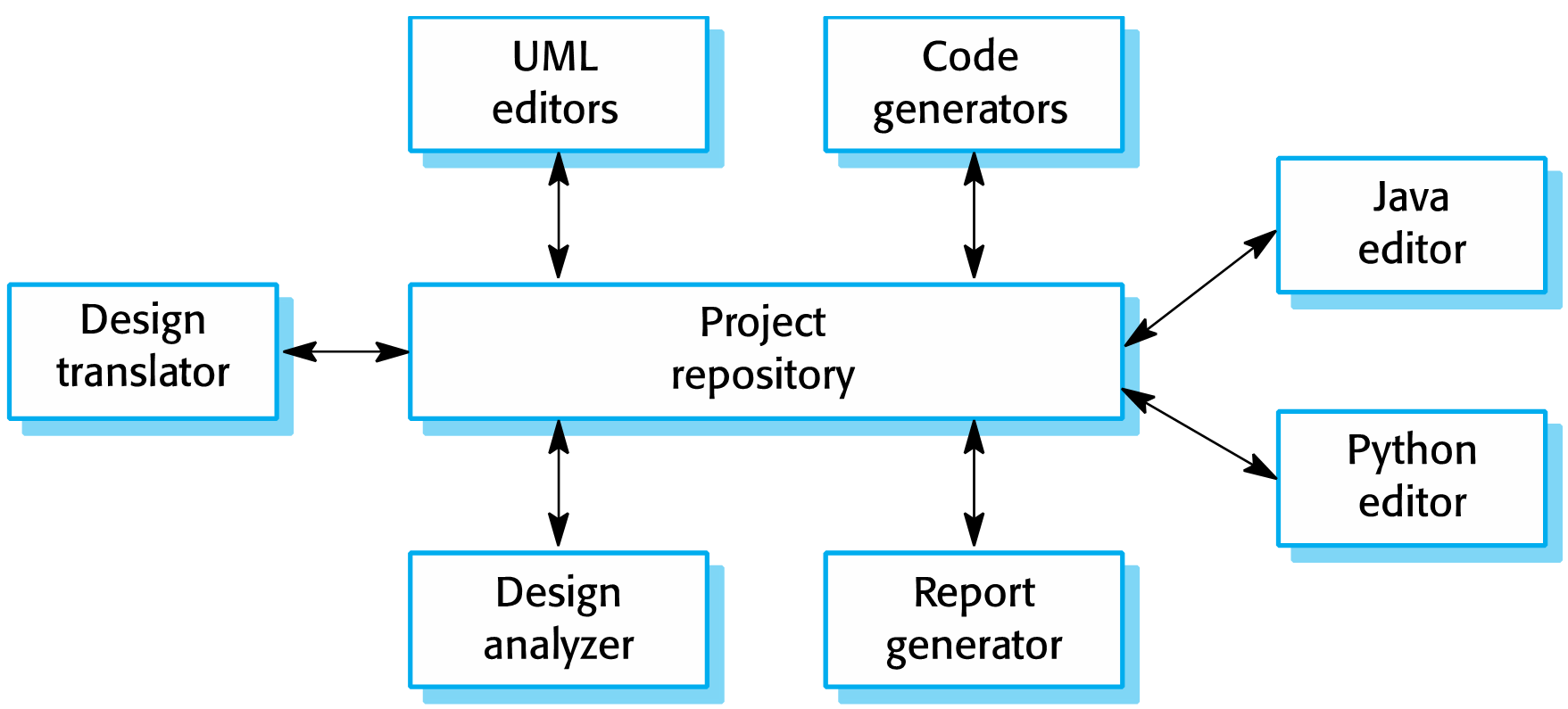
Figure A15: A Repository Architecture Pattern for an Integrated Development Environment9 9Taken from Sommerville, I Software Engineering, tenth edition, 2016
-
Event-Based Pattern
An Event-Based pattern is useful for event-based applications (Chapter 2 Section 3.4.3) in which a computer-based system responds to a stream of different event inputs either human or, in embedded control applications from physical sensors which are sampled. The latter type of CBS also often have hardware actuators which on receipt of a signal will cause a movement in a physical device e.g. turning a light on/off, adjusting the temperature of a heater, changing the position of the wing flaps on an aeroplane. The same data are often used to form the basis for displaying different graphs and charts.Problem Context:Events are maintained in an event queue, and can be processed in many different ways e.g. first come first served, in priority order or in a cycle, where each cycle is keyed to a clock. In a real-time system the length of the cycle time will also be governed by not only the needs of the problem but also the physical rates at which the input sensors can read and change values and the physical rates at which responses can actuators can cause a response. See 📷 Figure A16. There are two main types of architecture component: an Event Mediator that mediates the event queue and an Event Processor. The event flow starts with a client sending an event to an event queue which is processed by an Event Mediator. The Event Mediator receives the initial event and orchestrates that event by sending additional asynchronous events to event channels to execute each step of the process. Event Processors, which listen on the event channels, receive the event from the event mediator and execute specific business logic to process the event. It is common to have anywhere from a dozen to several hundred event queues in an event-driven architecture. See 📷 Figure A18. In a real-time control system where an event is a set of data from physical sensors, the Event Mediator will read the data from the sensors, examine the implications of different values and determine what events need to take place. Notifications are sent to the appropriate Event Processors to control the relevant actuators and display relevant charts.Problem Solution:📷 Figure A17 shows a high volume insurance claim call centre. 📷 Figure A19 shows a burglar alarm system.Example Problem:✓ Perform time-consuming tasks, such as downloads and database operations, "in the background," without interrupting your application
✓ Execute multiple operations simultaneously, receiving notifications when each completes.
✓ Wait for resources to become available without stopping ("hanging") your application.
✘ no guarantee if or when an event will be processedConsequences:One approach, is to use a “central mediator” when you want to orchestrate multiple steps within an event. Another approach is to use a Broker when you want to chain events together without the use of a central mediator.Implementation:📹 Watch this 50 minute talk by keynote talk by Martin Fowler in April 2017
The Many Meanings of Event-Driven ArchitectureX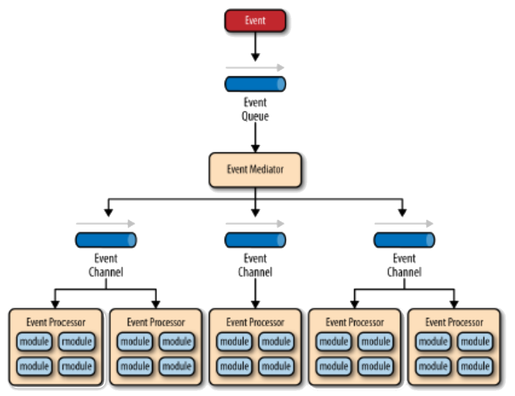
Figure A16: Event-based Pattern using Central Mediator10 10Taken from Richards, M., Software Architecture Patterns, O’Reilly, 2015.
X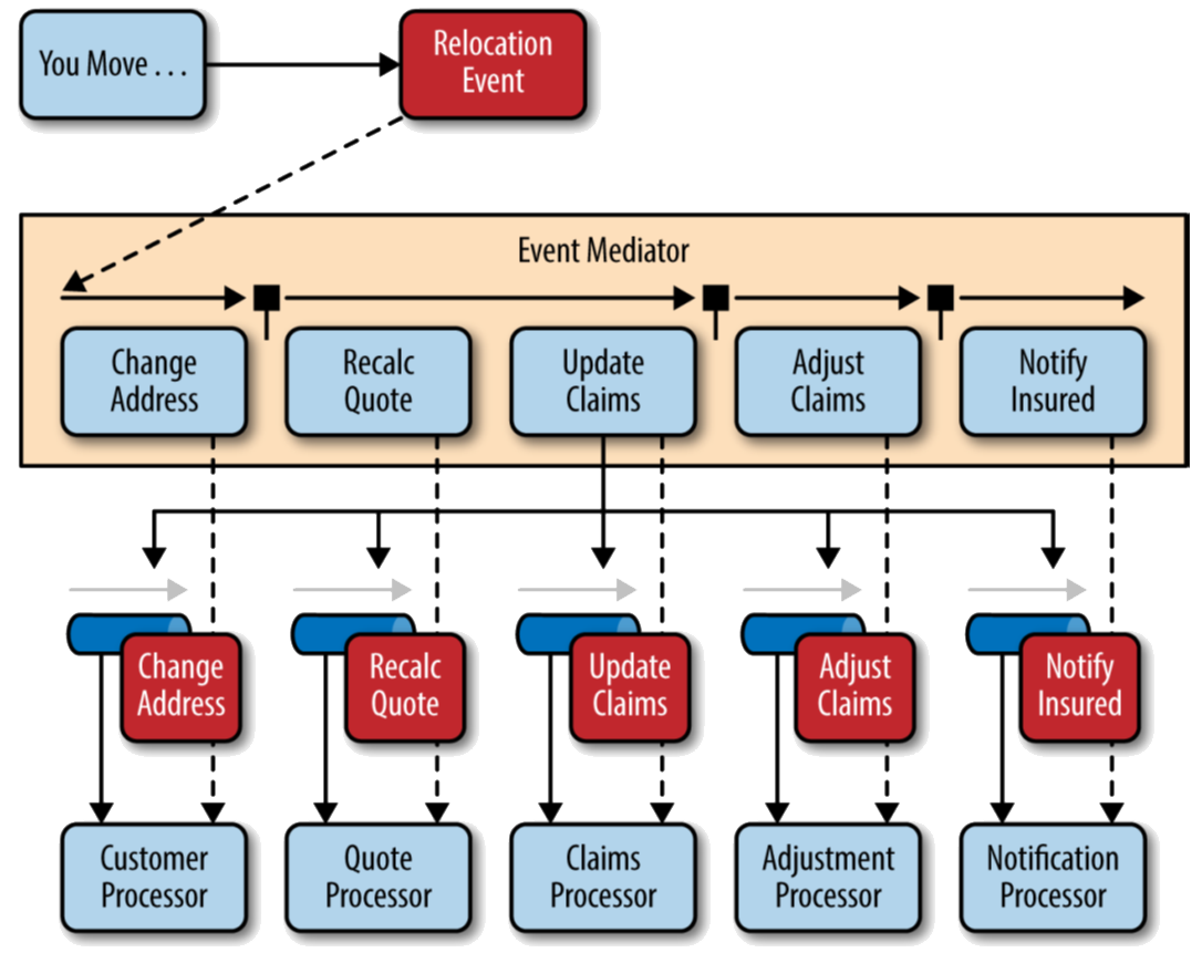
Figure A17: Insurance Claim Example X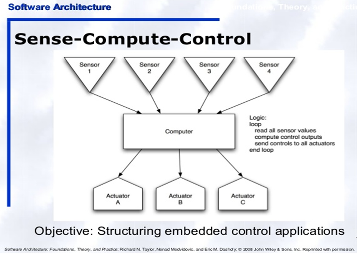
Figure A18: Industrial Control System X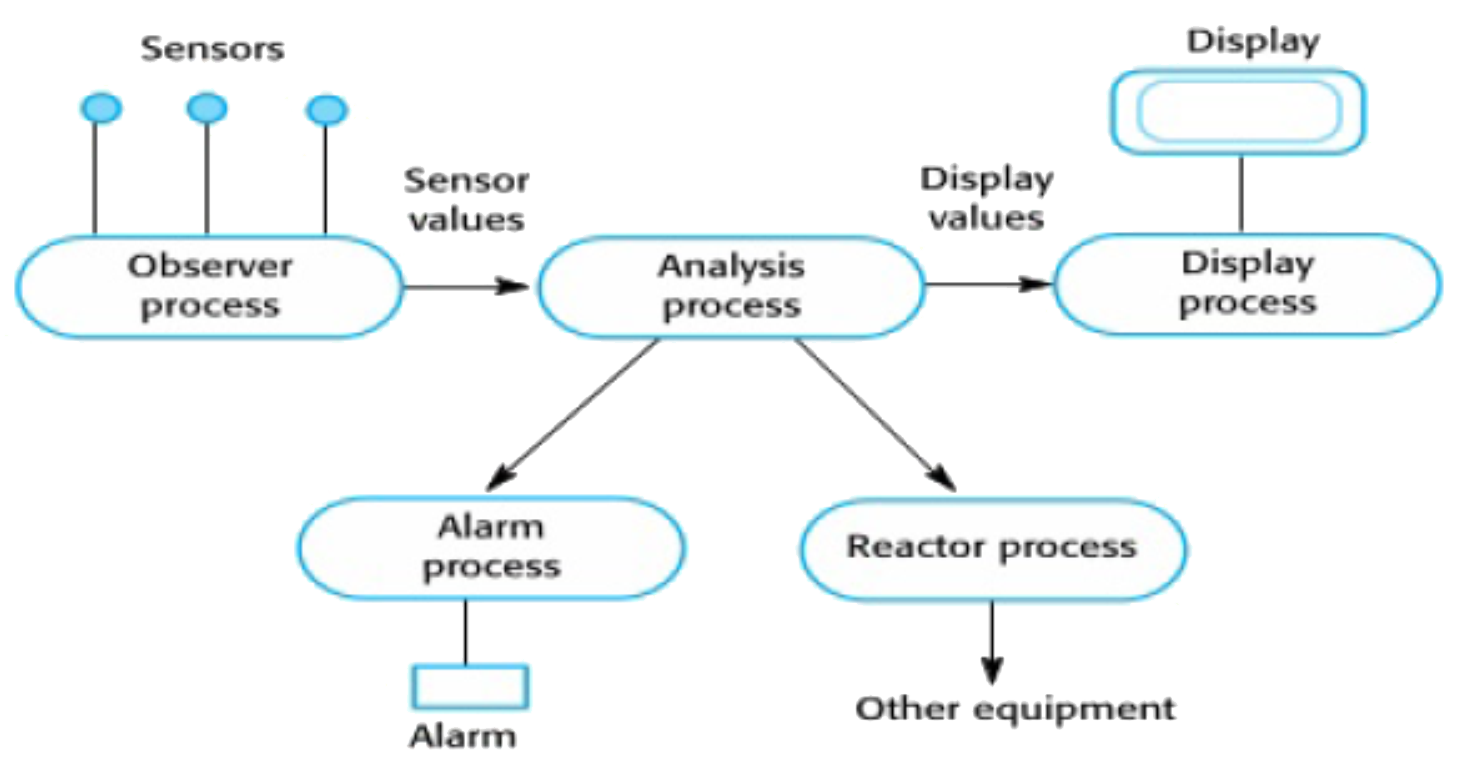
FigureA19: Burglar Alarm System -
Publish-Subscribe
This pattern is useful when many people (Subscribers) want access to similar sets of information that comes from a wide variety of different sources (Publishers). There is a clear delineation between publishers and subscribers. When publishers are also subscribers and subscribers are also publishers then this pattern effectively becomes an event-based pattern.Problem Context:The Publisher periodically publishes information and alerts signed up Subscribers to its availability. The Publisher maintains a list of Subscribers to each of which a procedure call is issued when new information is available. Subscribers register their interest with Publishers and provide them with their interface (the call-back) when the information is published. Subscribers can register or deregister their interest. In practice there are additional complexities. Some Publishers e.g. UK Government may not require anyone to register because the information is for everyone (Broadcast-Based); some publishers enable subscription by subscriber type (List-Based); some publishers enable subscription by topic type (Content-Based); some allow a combination. Similarly if subscriber groups change or the list of topics changes existing subscribers need to be informed. See 📷 Figure A20.Problem Solution:In an online job posting service, hiring managers are publishers, publishing job vacancies, and job seekers are Subscribers. 📷 Figure A21 shows what happens when a recruitment agency moves office and needs to communicate a change of address. Other examples are Tourist Information boards; mailing lists; social networks when you are notified of changes to someone you are connected to.Example Problem:✓ provides flexibility for asynchronous communications between two groups
✘ delivery of message is not guaranteed because the Publisher cannot be sure if the Subscriber is listeningConsequences:Typically publishers use an event bus to announce new information. The key issue is the extent to which Publishers actively Push information (i.e. alert their Subscribers) and/or Subscribers actively Listen for and Pull new information. The more urgent the information the more the Publisher and Subscriber need to operate synchronously. A common way to implement Publish-Subscribe is to use the 🔗 Observer [Gamma95] pattern using two classes: subjects and observers. To subjects add three methods: Attach(),Detach(), and Notify(). To observer add Update(). However note that the Observer pattern was designed largely for synchronous communication i.e. the observable notifies observers immediately when some event occurs whereas the Publisher/Subscriber pattern was designed with asynchronous communication in mind. Also, in the Observer pattern, the observers are aware of the observable whereas in Publisher/Subscriber publishers and subscribers don't need to know each other. They simply communicate with the help of message queues. In practice the “PubSub” pattern is often realised by some form of middleware.Implementation:X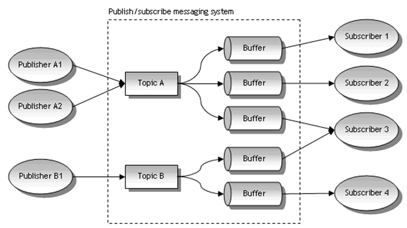
Figure A20: Generic Topic-Based Publish-Subscribe Pattern X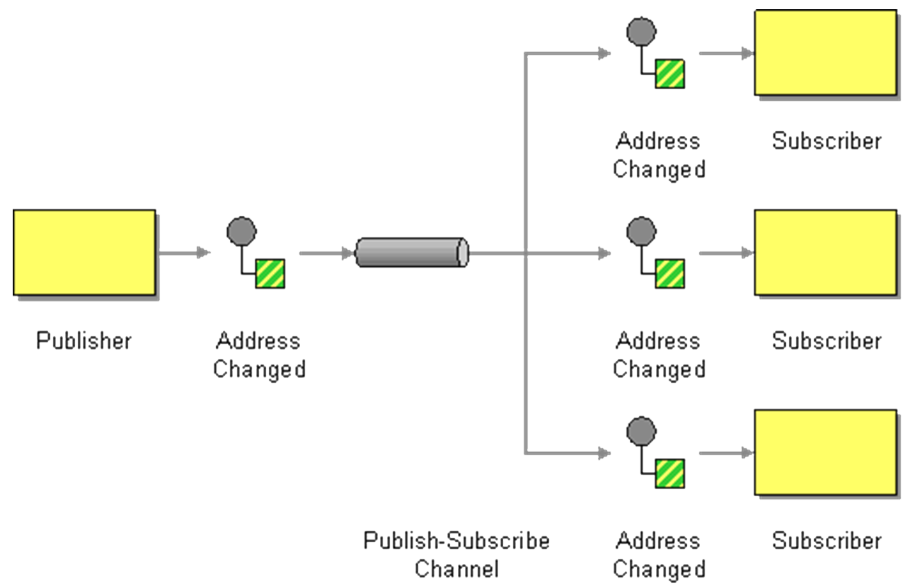
Figure A21: Changing Address on a Social media site -
Service-Oriented Architecture (SOA) and Microservices (MSA)
This pattern is useful when there is a need for the continuous delivery of large, complex applications offering a set of relatively independent software services. The model is similar to the Client-Server pattern but whereas in the Client-Server pattern there is a direct point-to-point connection between the client and the server, in SOA and MSA the connection is via an intermediary component. This reduces the coupling between the client and the server components enabling changes in one to take place independently of the other. This degree of independence from each other also enables server components to be built using a variety of development platforms without a client needing to know. This offers greater flexibility for service providers.
The difference in principle between SOA and MSA is component granularity which then has implications for implementation.
SOA & MSA often work best in large corporate data centres with well-defined boundaries, where there are rapidly developing new businesses and web applications, and/or development teams that are spread out, often across the globe. SOA is better suited for large and complex business application environments that require integration with many heterogeneous applications. The MSA pattern is well suited for smaller and well partitioned web-based systems. Both patterns are of the focus of intense interest in the context of Serverless Computing (See Sidebar).
Problem Context:To explain SOA and MSA it will be helpful to compare it to a monolithic system. In a monolithic system, user access and all service provision are under a single closed instance sharing a single database. In SOA and MSA, user access and service provision are separated.
In SOA and MSA application components provide services to other components via a communications protocol over a network. Services have well-defined published interfaces. The communication can involve either a simple data message being passed or it could involve two or more services coordinating connecting services to each other.
Figure A22 shows an SOA pattern in which communication between service consumers and service providers is achieved using an Enterprise Service Bus (ESB). Data storage is shared within all services in SOA. In general, any application using an ESB can behave as server or client. Figure A23 shows an e-commerce application.
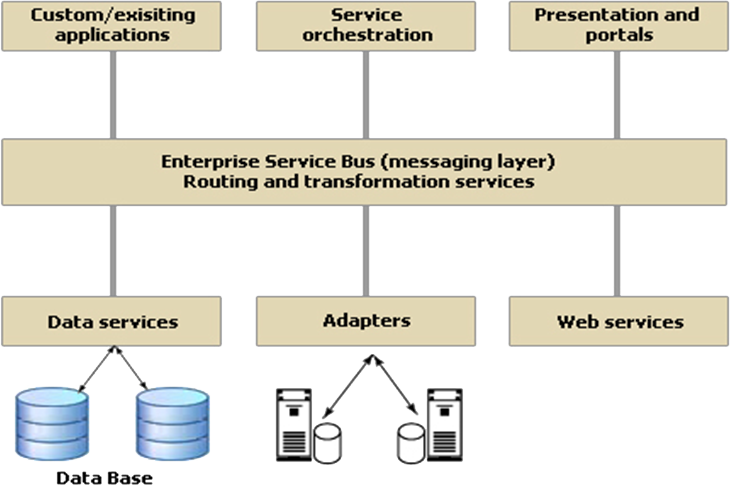
Figure A22: Service-Oriented Architecture The Microservices architecture (MSA) pattern takes the divide and conquer approach of SOA to lower level of granularity. For example, the processing of a customer order would be achieved by calling upon distinct microservices that stored and retrieved customer details and that stored and retrieved orders. Customer details and order details would be held in separate databases. The data aggregation logic to service a request to store or retrieve and a customer order would be contained typically in an API Gateway layer which is playing a similar role in principle to an ESB.
Service components in MSA are generally single purpose small services that do one thing well whereas in SOA they have more complexity and are often implemented as complete subsystems. A single business request in SOA may be constructed as a set of co-operating services. A single business request in MSA may be constructed as a set of smaller independent business requests each one serviced by a different component.
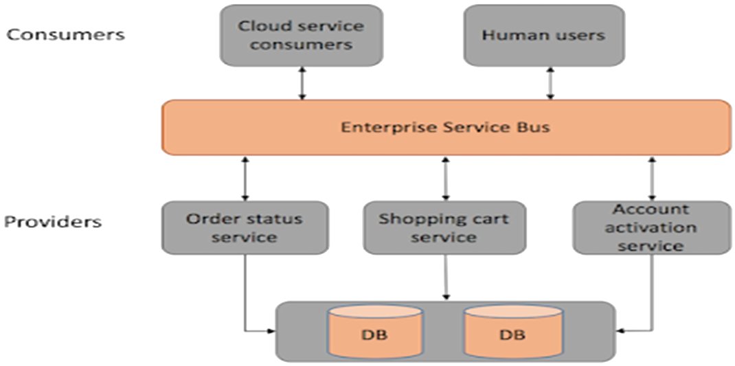
Figure A23: E-Commerce Application with a Service-Oriented Architecture Figure A23 each service has its own database or a database is shared between a few of microservices (a hybrid between pure microservices and SOA). These services are built around business capabilities and independently deployable by fully automated deployment machinery. There is a bare minimum of centralised management of these services, which may be written in different programming languages and use different data storage technologies.
Problem Solution:A server-side enterprise application normally must support a variety of different clients including desktop browsers, mobile browsers and native mobile applications. It might also expose an API for 3rd parties to consume or integrate with other applications via either web services or a message broker. The application handles requests (HTTP requests and messages) by executing business logic; accessing a database; exchanging messages with other systems; and returning a HTML/JSON/XML response.
Figure A24 shows a simple e-commerce application (see 🔗 https://microservices.io/patterns/microservices.html ) designed with a microservices architecture. It takes orders from customers, verifies inventory and available credit, and ships them. It consists of several components including the StoreFrontUI, which implements the user interface, and backend services for checking credit, maintaining inventory and shipping orders. The application consists of a set of services.
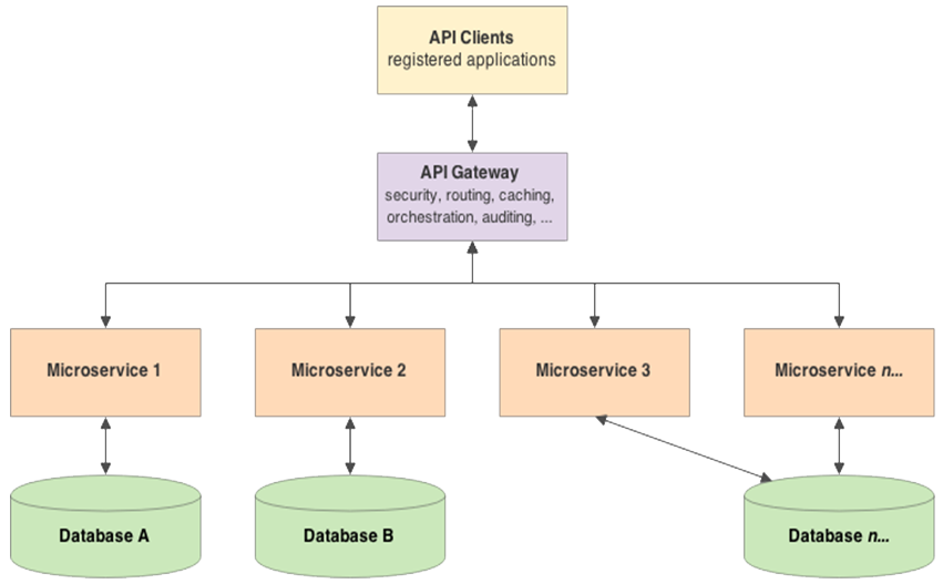
Figure A24: each service has its own database 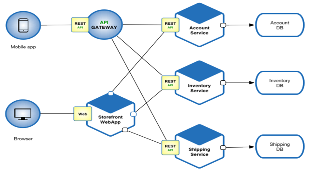
Figure A25: shows a simple e-commerce application Example Problem:✓ Enables the continuous delivery and deployment of large, complex applications.
✓ Better testability - services are smaller and faster to test
✓ Improved fault isolation
✓ Easier deployment - services can be deployed and maintained independently
✓ Organise the development effort around multiple independent teams especially if they are distributed around the globe
✓ Each component can have its own technology stack
✘ Not easy to decide what is a service in SOA or MSA
✘ Performance can suffer when tasks are spread out between different services
✘ Too many services can be confusing to maintain
✘ In SOA, ESB could become a single point of failureConsequences:The difference in granularity between SOA and MSA has implications for communication middleware. In both architectures, developers must implement an inter-service communication mechanism between services. Microservices is an approach to developing a single application as a suite of small fine-grained services, each running in its own process and communicating with lightweight protocols such as HTTP/REST etc mechanisms. SOA offers capabilities often not found in MSA e.g. mediation, routing, message enhancement, message and protocol transformation. MSA has an API layer between services and service consumers.
Implementation:📖 For a general discussion on service-oriented software engineering read Ch 18 of Sommerville, I. (2016) Software Engineering, 10th Edition, Pearson.
📖 https://dzone.com/articles/microservices-vs-soa-whats-the-difference
📖 https://dzone.com/articles/microservice-pattern-api-gateway
📖 https://www.infoq.com/microservices
📖 https://www.se-radio.net/2019/06/episode-370-chris-richardson-on-microservice-patterns/
📹 Watch Martin Fowler talk about Microservices Martin Fowler – Microservices
Serverless Computing
Whilst the principal role of a software architect is to design software, for distributed systems, understanding and selecting the deployment platforms has also become an integral part of the role.
Organisations buy or rent servers. Servers offer memory and processing capacity to run organisational IT infrastructure software e.g. operating systems, directory services, network management, printers, and to run the business applications that sit on top of the infrastructure e.g. a student record system, a warehouse management system, a human resources management database systems, an App Store.
The rental model emerged as global data storage and data processing requirements increased, and many companies recognised that they did not want to buy increasing numbers of computers, which they would then have to secure, maintain and replace, and deflect their focus from their mainstream business. In response to market demand, there are now many server rental providers some of the largest being Amazon, Google. IBM, HP, Microsoft (see 🔗 https://www.gartner.com/reviews/market/public-cloud-iaas/vendor/amazon-web-services/alternatives). The term “The Cloud” is a widely accepted but colloquial term that simply means that the servers on which an organisation’s data is stored or on which applications are running is outside the organisation, and the precise physical location in hidden.
The rental model allows different size servers to be selected and to be rented for long-term, short-term, even by the hour. There are a variety of costing models that broadly fall into two categories: storage and execution. Charges are for execution are normally a combination of CPU time used (fractions of a second) and RAM used (fractions of a Gigabyte). The rental payment models allow client organisations to flexibly scale up or scale down their needs as their own businesses require it.
Paying rent of course is an ongoing cost and clients of server rental companies are always seeking to reduce their costs. Clients’ business applications normally change faster pace than the enterprise infrastructure on which they run. This realisation combined with the use of service-oriented architectures and microservices using distributed components for building these business applications, provides clients with some flexibility over their buy v rent storage and execution requirements.
Server rental providers continue to entice clients through their pricing models and offering new services. One of the more recent innovations is the notion of Serverless Computing in which the server rental provider dynamically manages the allocation of machine resources. The name "serverless computing" is used because the server management and capacity planning decisions are completely hidden from the developer or operator. In a traditional environment, developers must provision and configure servers, install operating systems and continually manage the infrastructure. Sometimes this is known as Infrastructure as a Service.
This general trend towards infrastructure as a service is also leading to new variations on the notion of Software as a Service (SaaS). With a serverless architecture, you’re free to create, manage and deploy apps that scale on demand – without worrying about infrastructure. However, the notion of “serverless” can also apply to business applications. SaaS is a software distribution model in which a third-party provider, hosts applications, and makes them available to customers over the Internet e.g. Microsoft’s MS-Office. Another type of example is the various App Stores offered by Apple, Google which are known as Platform as a Service. Other variations (and new terms for them!) will emerge e.g. “Backend as a Service” (BaaS) services, “Functions as a Service” (FaaS).
📖 Serverless Architectures
📖 http://www.se-radio.net/2018/03/se-radio-episode-320-nate-taggart-on-serverless-paradigm/
📖 https://dzone.com/articles/what-is-serverless-computing
📹 Serverless Patterns and Anti-patterns