-
-
Three Phase Rectifier Circuits
- Three phase uncontrolled half wave circuit
- Three phase controlled half wave circuit
- Three phase uncontrolled full wave bridge circuit
- Three phase fully-controlled full wave bridge circuit
- Three phase half-controlled full wave bridge circuit
-
Uncontrolled half wave rectifier
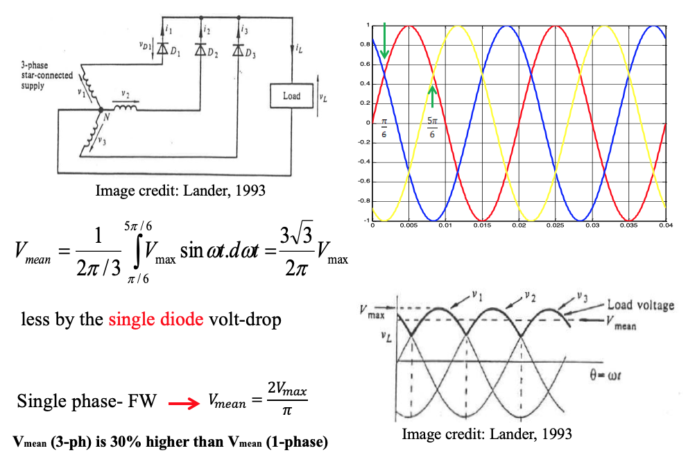
- Requires star –connected supply
- Each supply phase connected to load through diode, returned to neutral
- 2π /3 displaced (i.e. 120 degrees)
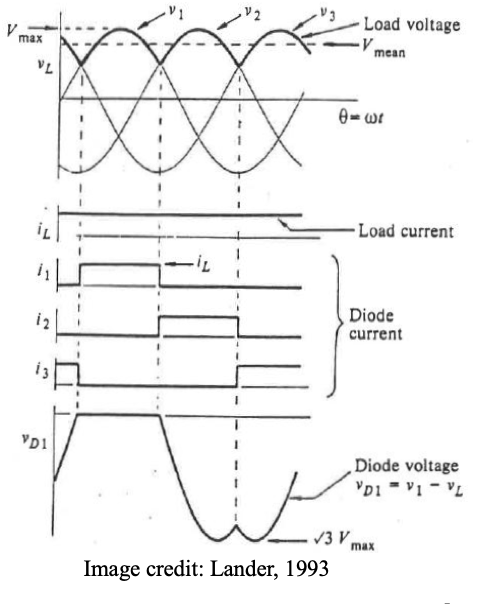
- Only one diode is conducting at any time. The phase with the highest instantaneous voltage forward biases its diode, which automatically reverse biases the other 2 diodes.
- Less ripple load current and voltage than single phase half wave
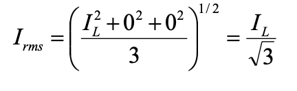
Assuming level d.c. load current IL, the diode currents shown are each blocks one-third of a cycle in duration. The r.m.s. value of the diode current for the required rating purposes for each diode can be derived using calculus, or more simply by taking the square root of the mean of the sum of the (current)2 over three equal intervals in the cycle, that is:
Example
A three-phase half-wave rectifier has a supply of 150V/phase. Determine the mean load voltage and the required diode rating, assuming the load current is level at 25 A. Assume each diode has a volt-drop of 0.7 V.Solution
Mean load voltage is: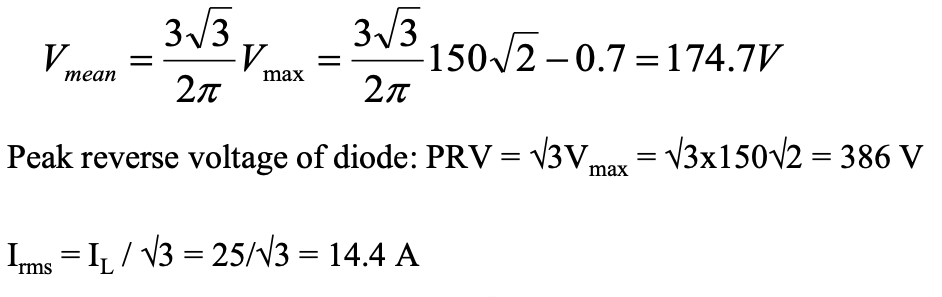
-
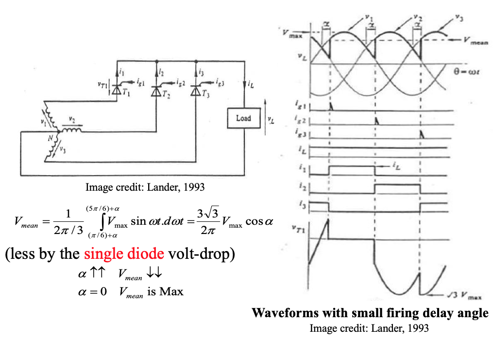
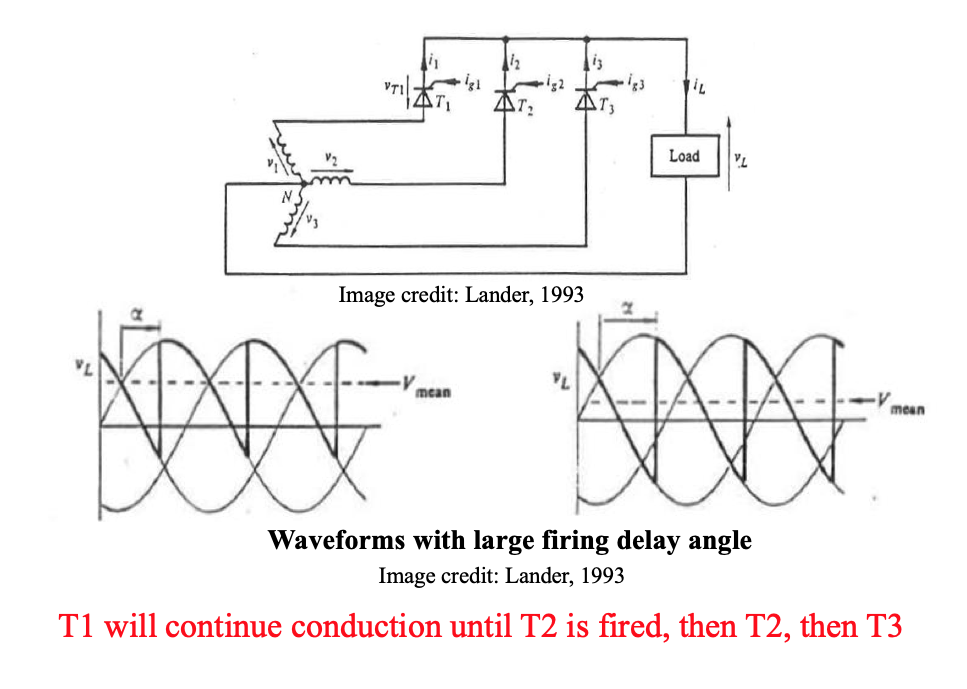
Controlled half wave rectifier
When the diodes are replaced by thyristors, the circuit becomes fully controllable. The mean load voltage is adjusted by controlling firing delay angle α.
Example
A three-phase half-wave controlled rectifier has a supply of 150V/phase. Determine the firing delay angle required to produce a mean load voltage output of 150.5 V. Assume a thyristor volt-drop is 1.5V and load current will be continuous.
Solution
Mean load voltage is: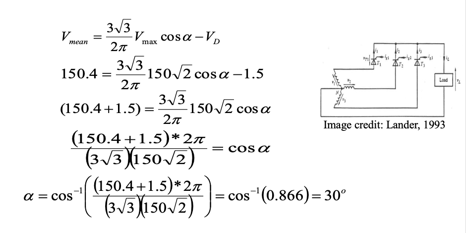
-
Uncontrolled full wave rectifier
The circuit operates such that only two diodes are conducting at any given instant, the ones connected to the two lines with the highest voltage between them. Thus when va is the most positive phase, diode D1 conducts and for 60°, vb is most negative so diode D6 is conducting. After 60° vc becomes more negative than vb and hence the load current will commute from diode D6 to diode D2.The load voltage follows in turn six sinusoidal voltage during one cycle these being va-vb, va-vc vb-vc, vb-va, vc-va and vc-vb. Although a star connected supply is shown, a delta connection can also be used (No neutral is required). Max voltage is line voltage.
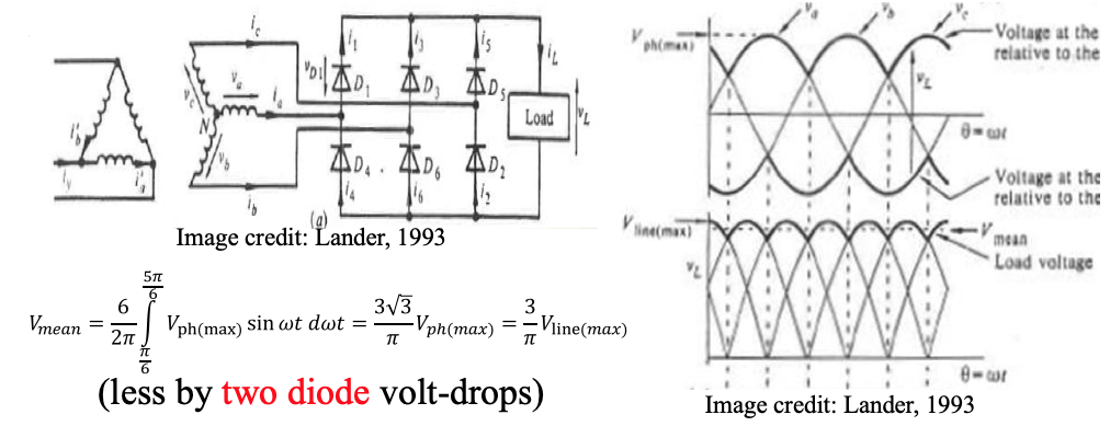
The diode current waveforms shown reveal that each diode conducts the full-load current for one third of a cycle (120º).
The a.c. supply current to be symmetrical, but of a quasi-square shape. However, the current waveforms are closer to a sinusoidal shape than those in the single-phase bridge connection.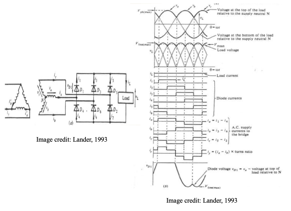
-
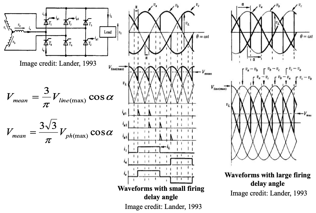
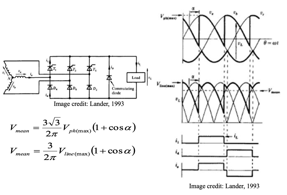
Fully-controlled full wave rectifier
The three-phase bridge can be made into a fully-controlled connection by making all six rectifying elements thyristors.
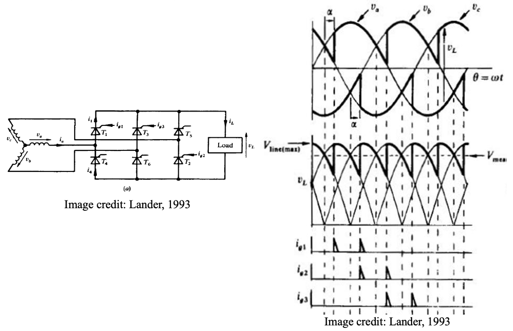
In order for the circuit to function, two thyristors must be fired at the same time to commence current flow. After T1, the next firing pulse will be to thyristor T2. However, thyristor T2 will not conduct unless at the same time thyristor T1 is pulsed. Hence, for starting purposes, the firing circuit must produce a firing pulse 60° after its first pulse. Once the circuit is running normally, the second pulse will have no effect, as the thyristor will already be in the on-state.
Activity
Open the interactive Excel file on GCU Learn titled: Three phase fully controlled full wave rectifier
Follow the instructions in the file to run the model for different values of firing angle α.
Verify the mean value of the output voltage DC waveform (at different α) using the mean voltage formula: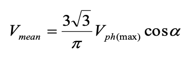
Example
A fully-controlled three-phase rectifier bridge circuit is supplied by a line voltage of 220 V.
Assuming continuous load current and a thyristor volt-drop of 1.5V, determine the mean load voltage at firing delay angles of 0°, 30°, 45°, 60°, and 90°.
Plot the waveform of the load voltage at a firing delay angle of 75°.
Solution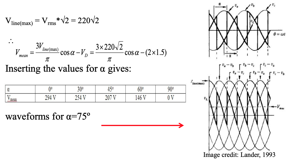
-
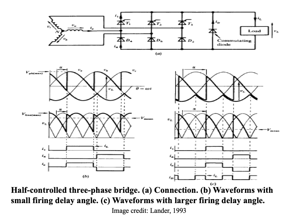
Half-controlled full wave rectifier
The half-controlled circuit is obtained by replacing three of the diodes in the uncontrolled case with thyristors.
Commutating diode is required to turn off the diode when voltage becomes negative.
Compared to the fully-controlled circuit, the half-controlled circuit is cheaper, has no starting problems, but has a higher harmonic content.
-
Check your understanding by answering the following:
- Identify the number of operating devices at any moment in time, when feeding load from supply, in the following converters:
(a) Three phase half wave uncontrolled rectifier
(b) Three phase half wave controlled rectifier
(c) Three phase full wave uncontrolled bridge rectifier
(d) Three phase full wave fully-controlled bridge rectifier
(e) Three phase full wave half-controlled bridge rectifier
- Draw the circuit diagram for the following three phase rectifiers:
(a) Half wave uncontrolled rectifier
(b) Half wave controlled rectifier
(c) Full wave uncontrolled bridge rectifier
(d) Full wave fully-controlled bridge rectifier
(e) Full wave half-controlled bridge rectifier
- Given any drawing of a converter circuit in this lecture, identify the name of the converter.
- The load in three phase full wave rectifiers has the capability of working in inversion mode.
Is this possible with both half-controlled and full-controlled full wave rectifiers? Explain your answer in detail. - Identify the number of operating devices at any moment in time, when feeding load from supply, in the following converters: