-
-
Introduction to DC/DC converters
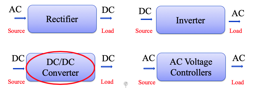
- DC/DC Converters convert a fixed-voltage DC source into a variable-voltage DC source
- DC equivalent to an AC transformer with a continuously variable turns ratio
- Like a transformer, it can be used to step down or step up a DC voltage source
- Widely used in traction motor control, DC voltage regulators, renewable energy sector.
We will study two main topics:
DC choppers
Principle of step down operation
Generation of duty cycle
Methods of switching control
Switching mode regulators
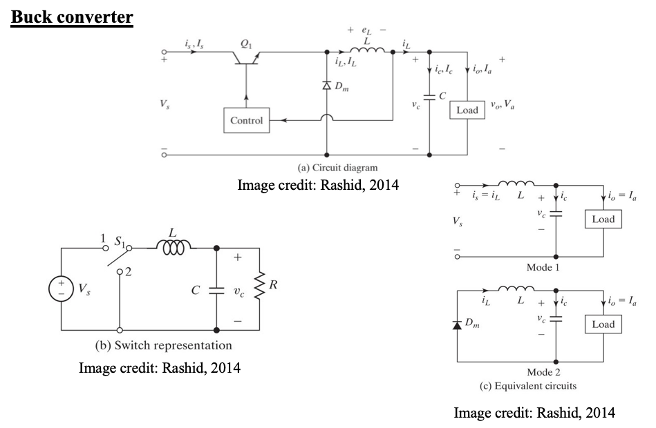
Buck converter
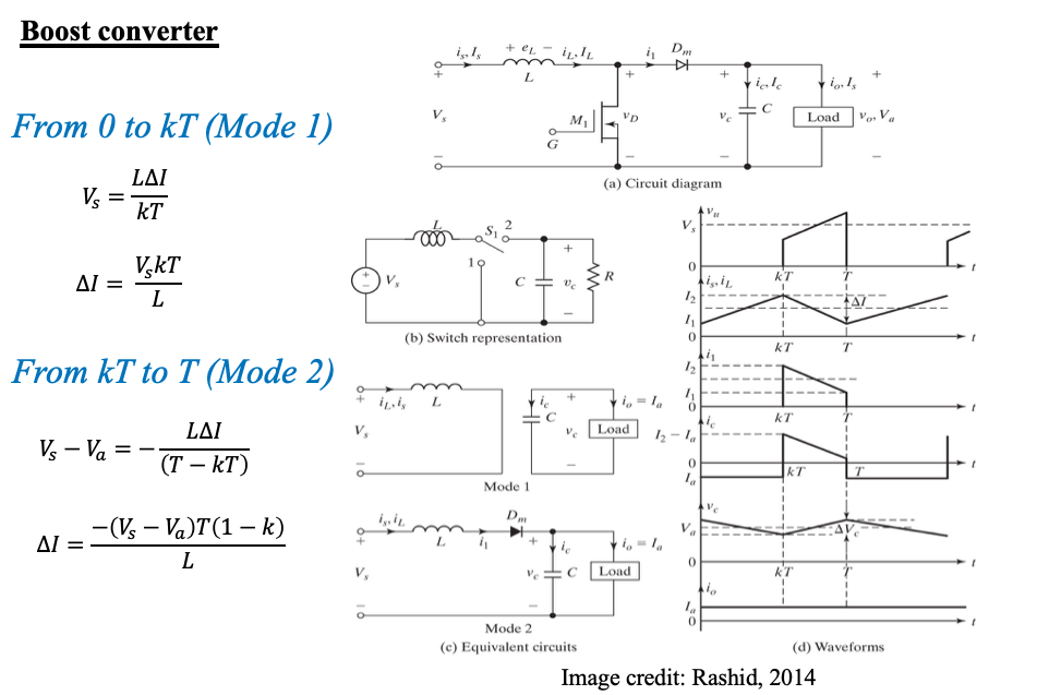
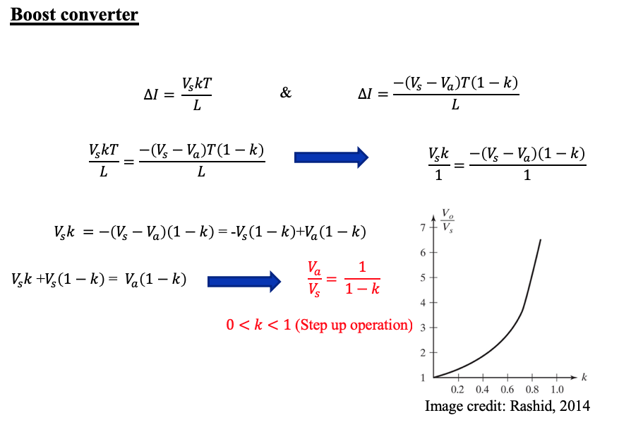
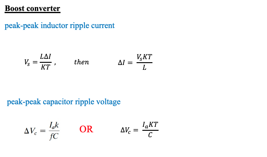
Boost converter
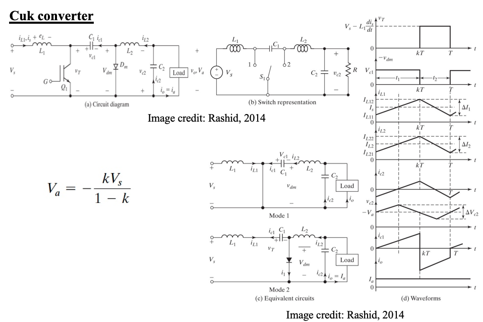
Cuk converter
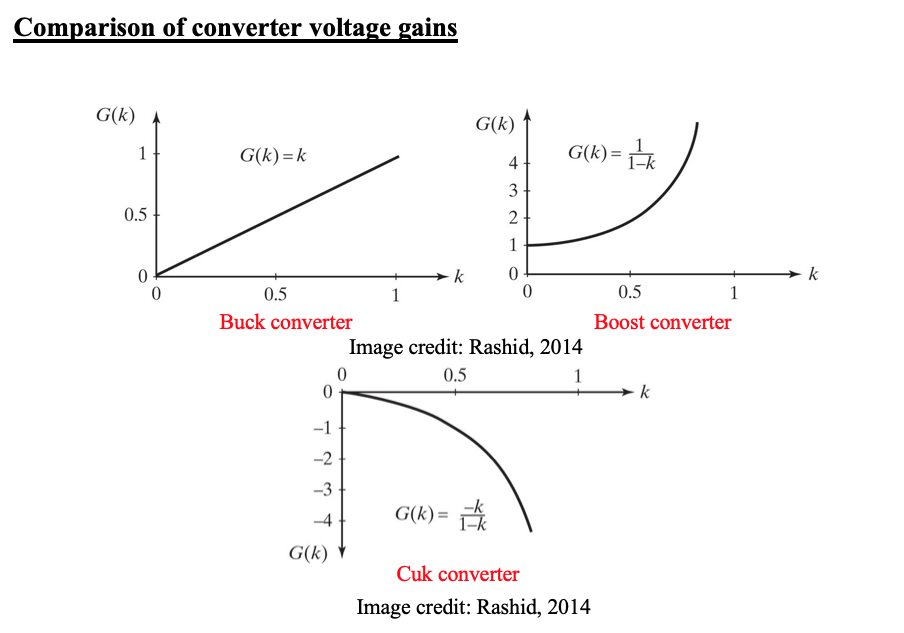
Comparison of converters voltage gains -
DC Choppers
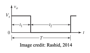
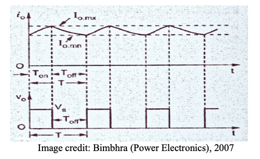
Principle of step down operation
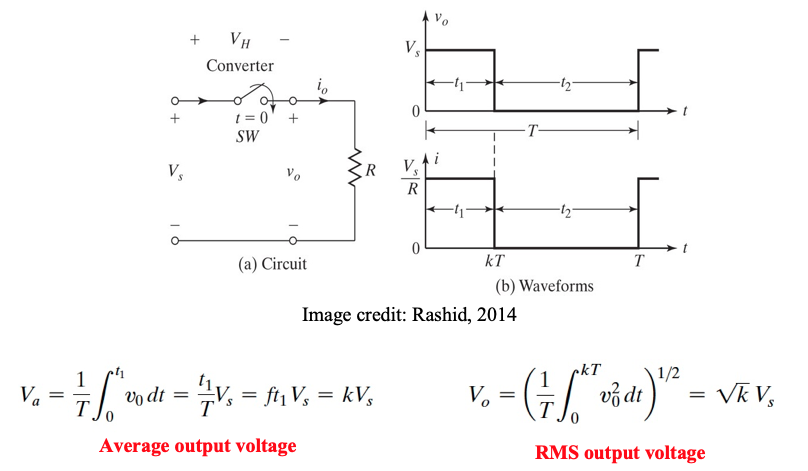
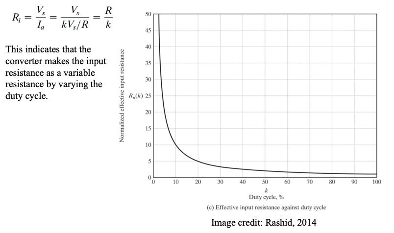
The effective input resistance seen by the source is:
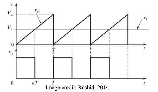
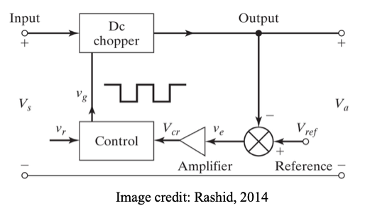
Generation of duty cycle
To generate a pulse width modulated (PWM) control signal with variable duty cycle:
1. Generate a triangular waveform of period T (carrier signal vcr).
2. Generate a DC reference signal vr
3. Compare these signals by a comparator to generate square wave gate pulse of width kT (to be applied to switching device)
4. As vr changes from 0 to Vcr, duty cycle changes from 0 to 1.
Methods of switching control
- Time ratio control
• Constant frequency control
•; Variable frequency control
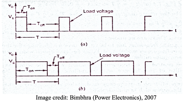
1. Constant frequency control
where T is constant, k is varied, variation of k means adjustment of pulse width. This is known as PWM control, produces fixed harmonics, filter design will be systematic and easy.
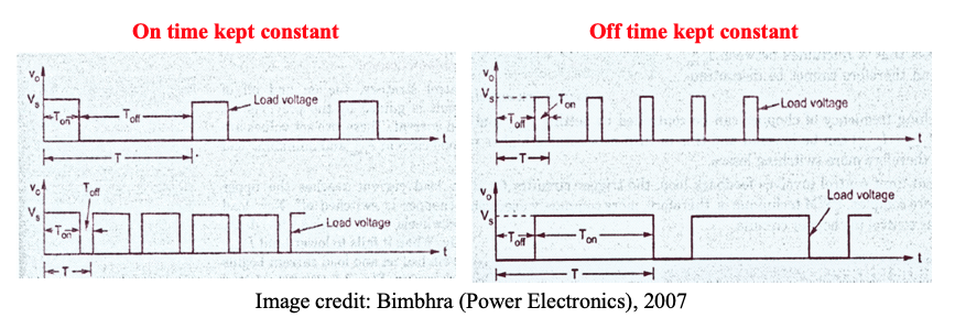
2. Variable frequency control
k is constant however T is varied, this is known as Frequency Modulation FM
Compare PWM and FM?
• Wider range of frequencies to obtain full range of voltages,
• Possibility of signal interference with signalling,
• Produces harmonics of unpredictable frequencies,
• Filter design will be quite difficult.
3. Current limit control
Switch when current exceeds either of the two limits
- Time ratio control
-
Switching mode regulators
- Output of DC choppers is discontinuous and contains harmonics
- The ripple content is normally reduced by an LC filter to generate a regulated output DC voltage.
- Basic topologies include:
1. Buck converter(step down) Vout < Vin
2. Boost converter (step up) Vout > Vin
3. Cuk (step up/down)
Example
A buck converter has the following parameters:-
Vs = 50 V, Vo = 20V, Io = 10A, f = 100kHz, C = 100 μF
Current flow in the inductor is just continuous.
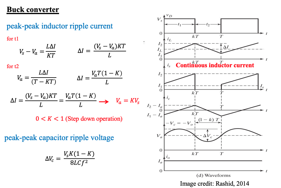
(a) Sketch waveforms for all converter components
(b) Determine value of inductance ‘L’ and rms current in ‘L’
(c) Determine peak-to-peak ripple voltage in output
Solution
(a) Sketch waveforms for all converter components
Switching frequency =100kHz, T= 1/f = 1/100kHz = 10μs
Duty Cycle = Vo/Vs = 20/50 = 0.4
Ton = T * (duty cycle) = 10 x 0.4 = 4 μs
Toff = T – Ton = 10 – 4 = 6 μs
Average inductor current = Io = 10A
Peak inductor current ; T* Io = 0.5 * T * Ip
Ip= 2 *Io = 2 * 10 = 20A (area of triangular waveform)
(b) Determine value of inductance ‘L’ and rms current in ‘L’
During ON condition:-
Vs – Vo = L diL/dt
50 – 20 = L (20/4μs)
L = 30/5 μH = 6 μH
RMS Current in Inductance (Using integration of triangular waveform)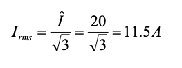
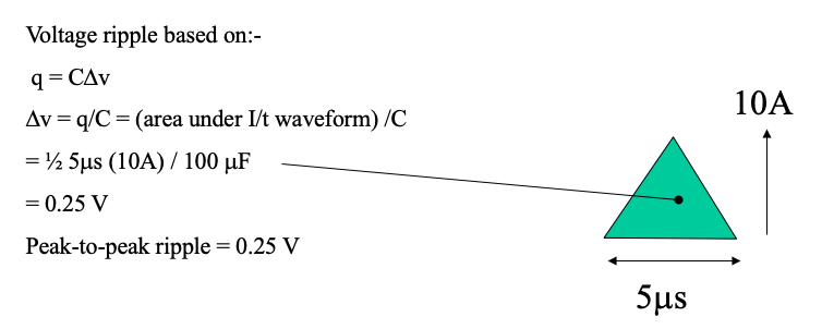
(c) Determine peak-to-peak ripple voltage in output
-
Check your understanding by answering the following:
- For DC chopper, derive expressions for mean and RMS output voltage.
- With the aid of appropriate sketches, discuss how a pulse width modulated control signal with variable duty cycle can be generated from a triangular wave to control a dc/dc converter.
- With the aid of waveform schematics, discuss and explain THREE different methods of switching control in dc/dc converters.
- Compare the merits and demerits of pulse width modulation and frequency modulation techniques of switching control in dc/dc converters.
- For Buck converter, sketch waveforms for diode voltage, switch current, inductor current, diode current and capacitor current.
- Given the drawing of any switching mode regulator circuit in this lecture:
(a) Identify the name of the converter.
(b) State the input-output voltage transfer function (voltage gain)
(c) Draw the equivalent circuit of the converter when the switch is turned on and similarly when the switch is turned off.
(d) State the mode (i.e. switch on or off) where the inductor is charging/discharging - Insert Content Here 6
- Insert Content Here 7