-
-
Introduction to DC/AC converters
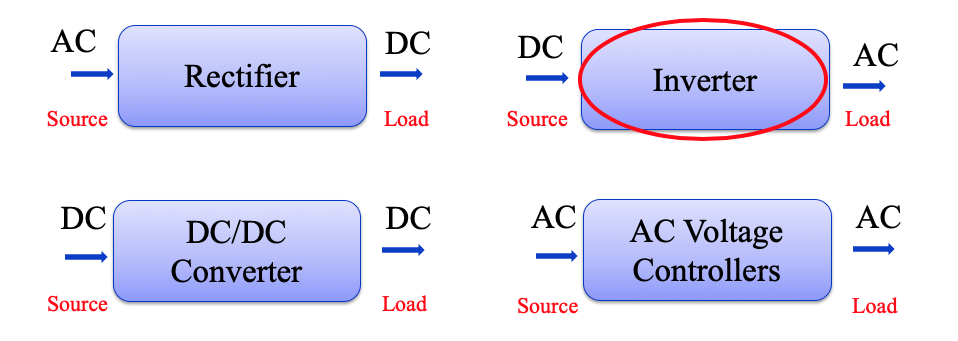
- DC/AC Converters are also known as inverters.
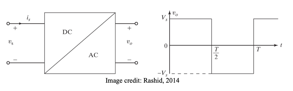
- The function of an inverter is to change a DC input voltage to a symmetric AC output voltage of desired magnitude and frequency.
- Output voltage/frequency can be both fixed or variable
- Output AC voltage of inverters are non-sinusoidal (contain harmonics), and therefore in some applications may need filters.
- Inverters are widely used in industrial applications, e.g. variable speed drives, renewable energy, transportation, uninterruptible power supplies.
-
Types of inverters
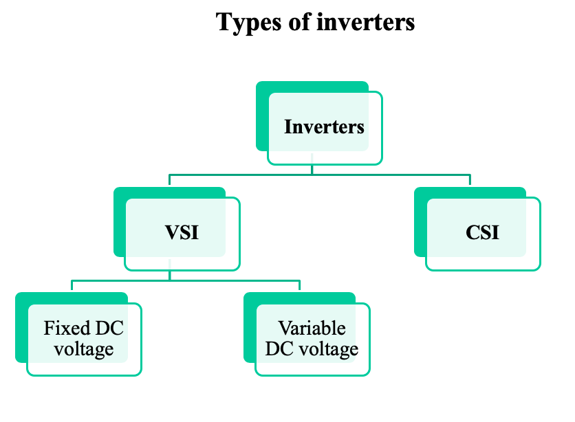
In general, there are two types of inverters:
1. Voltage source inverters (VSI): the input is a dc voltage supply and the inverter converts the DC voltage into an AC output voltage. Ideally it can deliver unlimited current at controllable terminal voltage.
2. Current source inverters (CSI): the input is a DC current source and the inverter converts this input DC current into an AC output current. Ideally it can deliver unlimited terminal voltage at controllable output current.
-
Voltage source inverters
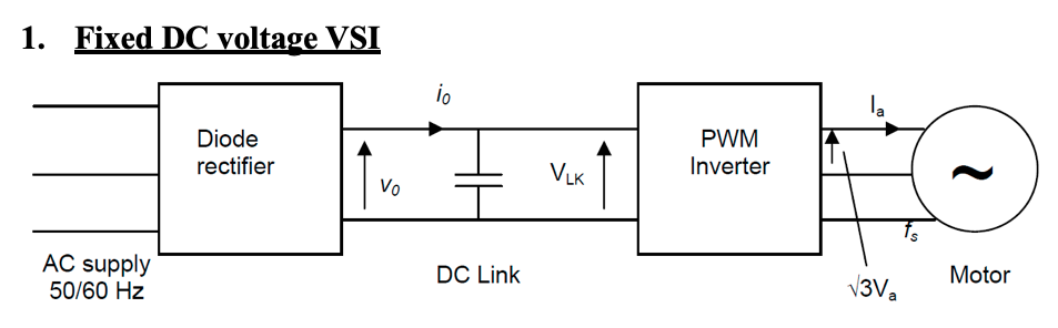
- The DC link voltage is fixed as it is generated by an uncontrolled diode rectifier.
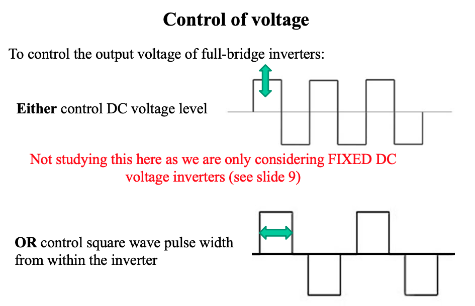
- To control inverter output voltage, the gain of the inverter is varied which is normally accomplished by pulse width modulation (PWM)
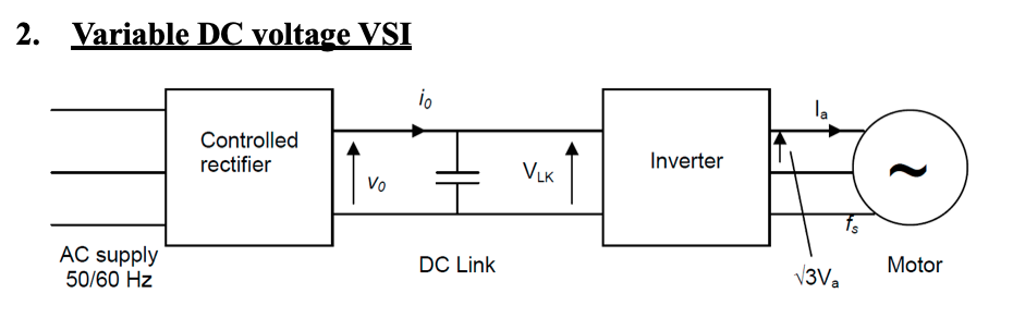
- The controlled rectifier varies the DC input voltage to the inverter to control output voltage of the inverter at the same time the inverter output frequency is varied.
- Inverter gain is maintained constant.
- The capacitor smooths the DC input voltage to the inverter to an effectively constant value.
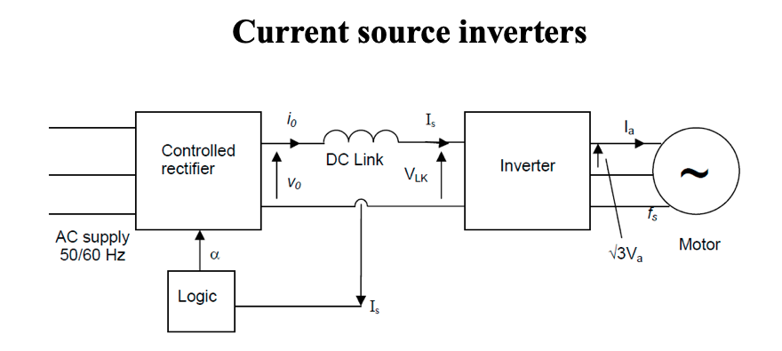
- To generate a constant and controllable DC current in the DC link, a controlled rectifier has to be used with a feedback loop to maintain the desired DC link current value.
- The feedback loop changes delay angle α in the rectifier as required to control DC link current.
-
Fixed DC voltage VSI
For our module, we will focus our study on Type 1: Fixed DC voltage VSI
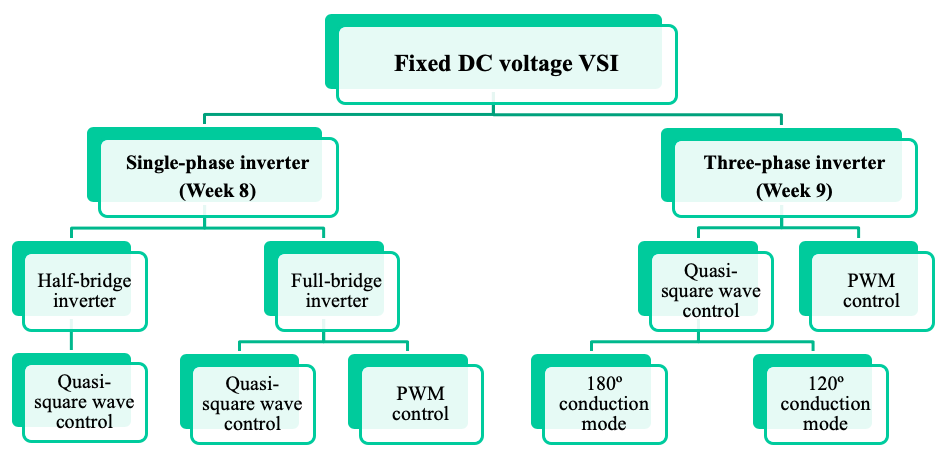
Single phase inverters
There are two circuit topologies commonly used for inverters. They are:
(a) The half-bridge inverter, and
(b) The full-bridge inverter.
For certain low power applications the half-bridge may be suitable but the full-bridge is more convenient for adjustment of the output voltage by pulse width modulation techniques.
The half-bridge, however, is the basic building block for the full-bridge.
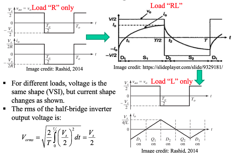
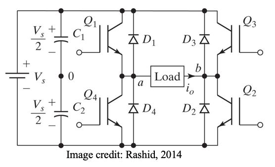
The half-bridge inverter
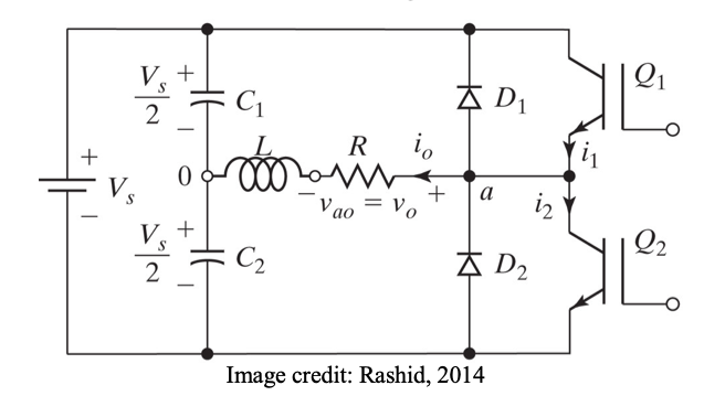
- The DC supply is split by the two capacitors C1 into two equal voltages to provide access to a mid-point “0”
- The AC load is connected between terminals “a” and “0”.
● To operate the inverter to provide an AC output, the switches Q1 and Q2 are turned ON and OFF alternately, each switch being kept ON for one half period of the AC, while the other is kept OFF
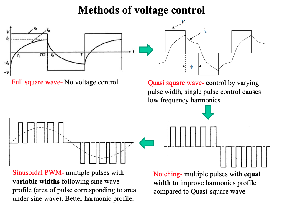
● Operated with quasi square wave output
- Unlike the half-bridge inverter, no need for a split DC supply
- The AC load is connected between terminals “a” and “b”.
- No connection to terminal “0”.
- Can be looked at as two half-bridge inverters.
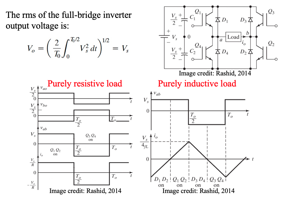
The full-bridge inverter
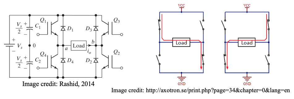
- Switches Q1 and Q2 are turned ON and kept ON for one half-period of the AC. This is the positive voltage half-period.
- Next, switches Q1 and Q2 are turned OFF and the switches Q3 and Q4 are turned ON and kept ON for the duration of the negative half-period.
-
Sinusoidal pulse width modulation
To generate a sinusoidal weighted PWM control signal:
- A reference sinewave of the desired output frequency is generated
- The sinewave s compared to a triangular (carrier) wave as shown
- The crossover of the two waves determine the firing instants
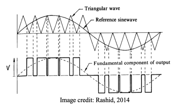
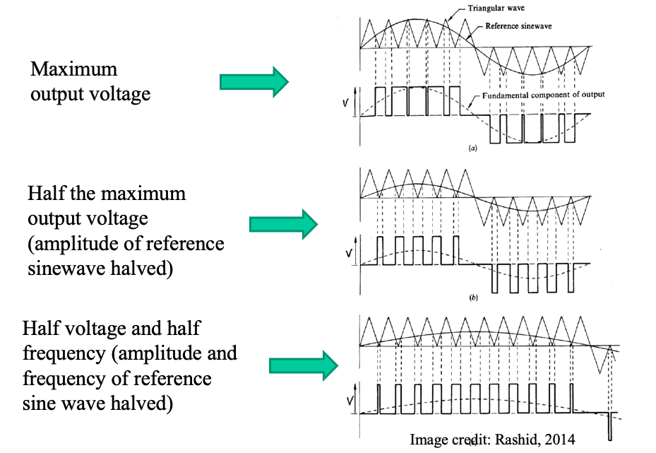
- The ratio of the height of the reference sine wave to that of the triangular wave is known as the modulation index.
- The number of switching pulses per half cycle is determined by the frequency of the triangular (carrier) wave. This is called the switching frequency which corresponds to the speed at which the semiconductor devices turn ON and OFF.
- The frequency of the reference sinewave determines the main AC output voltage frequency. This is called the fundamental frequency.
- The ratio of the switching frequency to the fundamental frequency is called the frequency ratio, and the higher it is the lower the harmonic content and the easier it is to filter out those harmonics.
- However, with high frequency ratios, the switching frequency of the devices is high causing high switching losses; hence the tradeoff between losses and harmonic profile. A typical minimum frequency ratio is in the range of 20.
-
Check your understanding by answering the following:
- What is the main function an inverter?
- Name some industrial applications of inverters.
- What is the difference between voltage source and current source inverters?
- With the aid of a simple sketch, explain briefly how a current source inverter operates.
- For the half-bridge inverter:
(a) Draw the circuit diagram
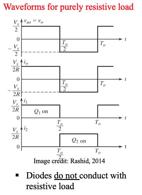
(b) Sketch waveforms for load voltage and current for purely resistive load highlighting the devices conducting
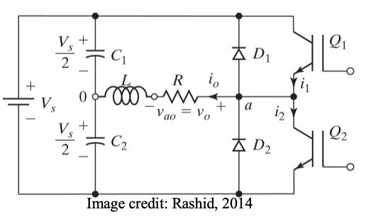
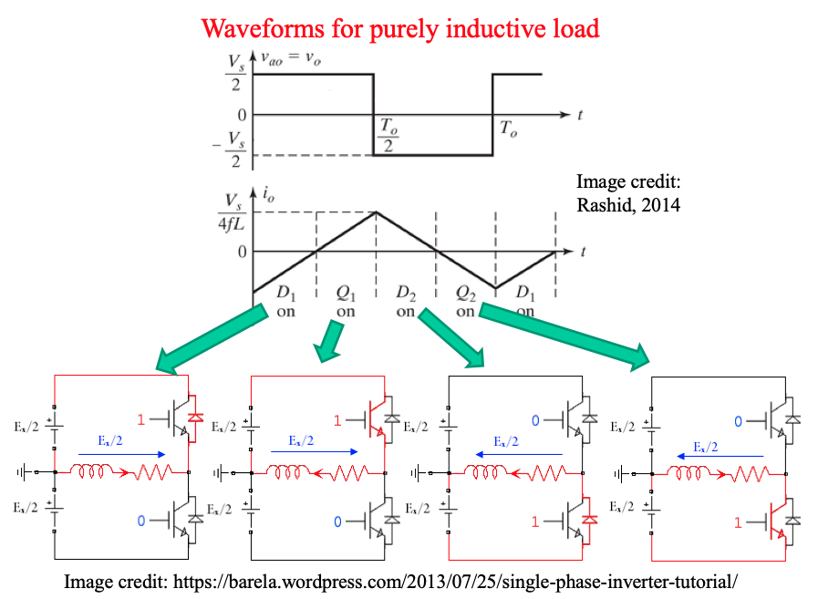
(c) Sketch waveforms for load voltage and current for purely inductive load highlighting the devices conducting