-
-
-
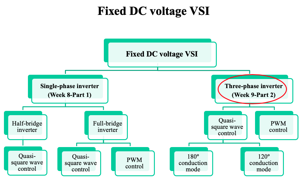
Introduction to three phase inverters
- The three phase inverter derives its importance from the fact that most a.c. industrial equipment, such as motors, are designed to work from three phase a.c. supplies.
- Nowadays, three phase inverters are also widely used in grid integration of renewable energy sources.
-
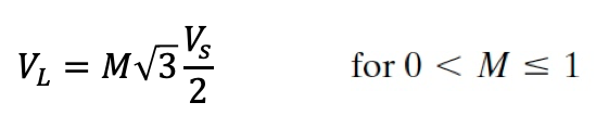
1. 180º conduction mode
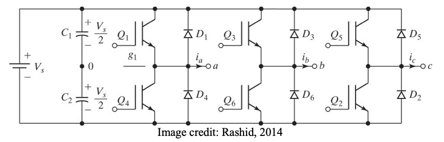
● Three single-phase half-bridge inverters
● For phase “a”, Q1 is ON for half the ac period (180 degrees), while Q4 is OFF for that half period. Then Q1 is turned OFF and Q4 is turned ON for the next half period.
● For phase “b”, Q3 and Q6 operate in a similar manner to phase “a”, but is shifted by 120 degrees (one third of a.c. cycle)
● For phase “c”, Q5 and Q2 operate in a similar manner to phase “b”, but is shifted by 120 degrees (one third of a.c. cycle)
● Each switching device conducts for 180 deg.
● At any moment in time, three devices are conducting.
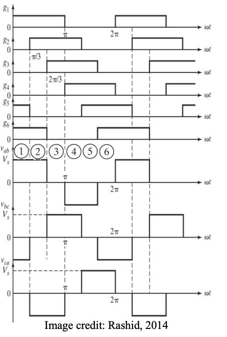
● Dividing the 360º into six sections of 60º, the figure shows the switching action in each section.
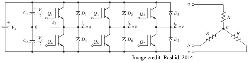
● When the load is connected in star, each load impedance comes in series with a line.
● The internal switchings of the inverter only change the interconnection from the dc source to the load terminals.
● The switching pattern and timings in the inverter are the same, irrespective of whether the load is Δ-connected or star-connected.
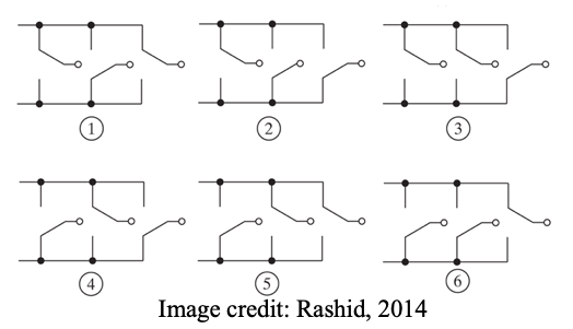
What this means is that we get six different circuit configurations, each one lasting for 60 degrees in one period.
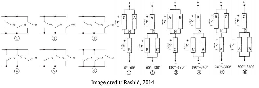
● In each of the circuit configurations shown, we notice that two of the load impedances are in parallel.
● This parallel combination is in series with the third impedance and the dc voltage is applied across this series-parallel circuit.
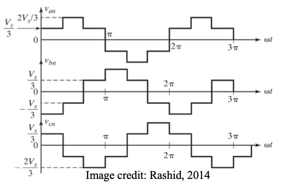
● If we use the neutral terminal N as the reference to express the voltage of each phase, then the polarity of the voltage of a load phase will be negative when it appears below N, and positive when it appears above N.
● This will be a six-step waveform, in conformity with the six circuit configurations.
● The middle step in each half-period will have a magnitude equal to (2/3)V and the two steps on either side will have magnitudes equal to (1/3)V.
2. 120º conduction mode
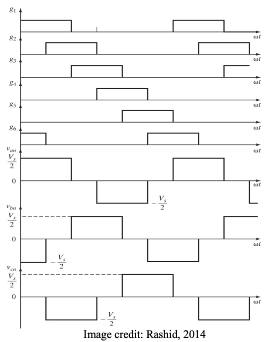
● An alternative mode of operation is when each device conducts for 120 degrees and only two devices are conducting at any time.
● On this basis we can derive voltage output waveforms as shown.
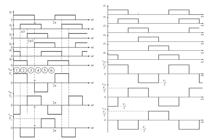
3. PWM control mode
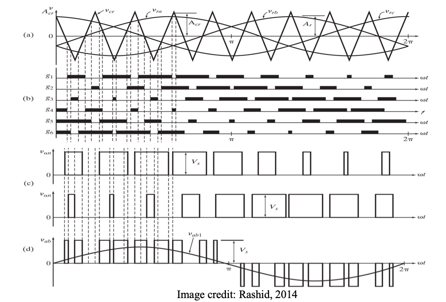
● The PWM technique can be applied to three phase inverters as illustrated.
● Three reference sinewaves modulate the high frequency triangular wave to determine the firing instants of each power electronic device.
● The explanation of these waveforms is similar to that developed for the single-phase inverters. Line voltage waveforms can be obtained from the appropriate phase voltage waveforms by subtraction.
● Waveforms shown on next slide.
● Depending on the modulation index M, the line voltage RMS voltage is:
-
Check your understanding by answering the following:
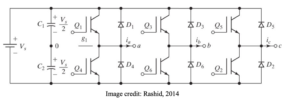
- Draw the circuit diagram for a three phase inverter.
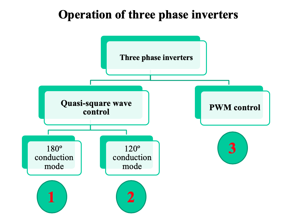
- State the name of THREE methods of control of three phase inverters.
- How many devices conduct at any moment in time using:
(i) 180º conduction mode?
(ii) 120º conduction mode?- State whether the following statements are TRUE or FALSE:
(i) In 180º conduction mode, each device conducts for a third of cycle.
(ii) In 120º conduction mode, each device conducts for a third of cycle.
(iii) In 180º conduction mode, the inverter switching state changes every 60º.
(iv) In PWM control mode, one reference sinewave modulates the high frequency triangular wave to determine the firing instants of all device.
(v) In PWM control mode, the output line voltage RMS voltage is directly proportional to modulation index.- To which mode of control in three phase inverters does each of the following set of waveforms belong?
- The six-step voltage waveform shown below is:
(i) Line-to-line voltage with star-connected load
(ii) Line-to-line voltage with delta-connected load
(iii) Line-to-neutral voltage with star-connected load
(iii) The standard inverter output voltage irrespective of type of load
Select ONE correct answer from the above.
- Insert Content Here 6
- Insert Content Here 7