-
-
What are Harmonics?
● The presence of harmonics in electrical systems means that current and voltage are distorted and deviate from sinusoidal waveforms.
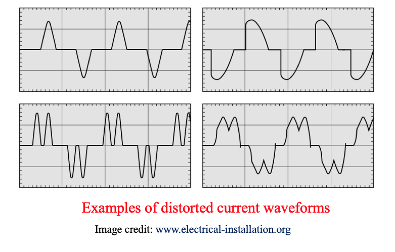
Concept and causes of Harmonics
● Harmonic currents are caused by non-linear loads connected to the distribution system.
● A load is said to be non-linear when the current it draws does not have the same waveform as the supply voltage.
● Variable speed motors and drives, photocopiers, personal computers, laser printers, fax machines and battery chargers are examples of non-linear loads
● The flow of harmonic currents through system impedances in turn creates voltage harmonics, which distort the supply voltage.
● Harmonics increase power system heat losses and power bills of end-users
-
Fourier series analysis of harmonics
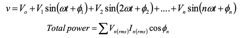
The Fourier theorem states that all non-sinusoidal periodic functions can be represented as the sum of terms (i.e. a series) as follows:
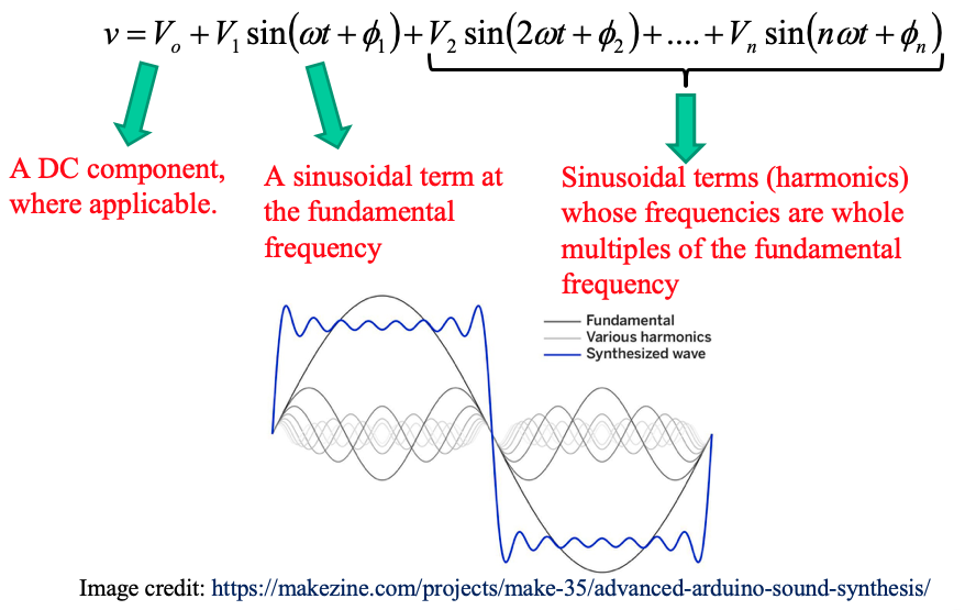
The harmonic of order h (commonly referred to as simply the hth harmonic) in a signal is the sinusoidal component with a frequency that is h times the fundamental frequency.
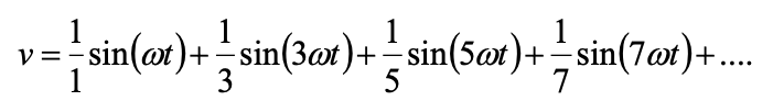
• DC component V0 = 0 (since positive area=negative area)
• Only odd order harmonics for square wave (since odd function)
• No even order harmonics V2 = V4 = V6 = V8 ..... = 0 (since odd function)
Activity
Open the interactive Excel file on GCU Learn titled:
Harmonics.xls
Use the interactive file to build a square wave (as in slide 5) using odd harmonics only (as in the Fourier series equation) up to the 9th harmonic.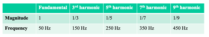
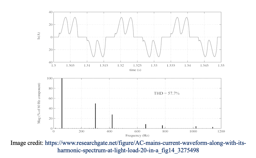
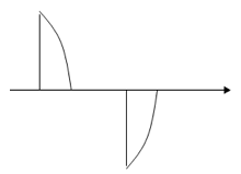
The figure shows an example of a current wave affected by harmonic distortion on a 50Hz electrical distribution system. The distorted signal is the sum of a number of superimposed harmonics:
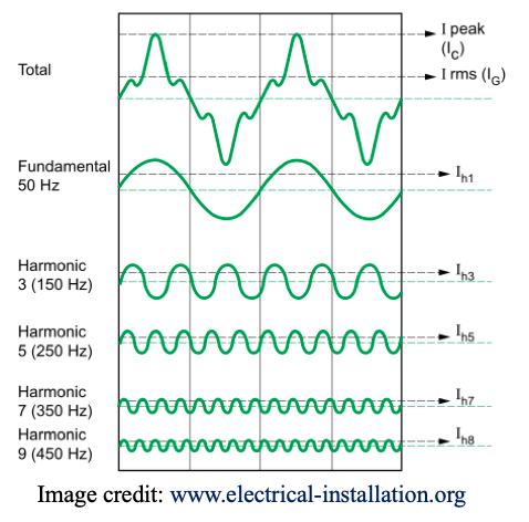
• The value of the fundamental frequency (or first order harmonic) is 50 Hz,
• The 3rd order harmonic has a frequency of 150 Hz,
• The 5th order harmonic has a frequency of 250 Hz,
• etc ....
Calculations using harmonics
Total power generated by a harmonic signal is due to sum of powers at each harmonic:
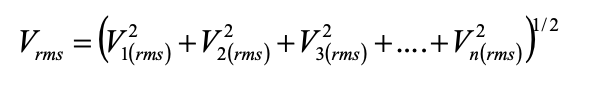
The RMS voltage of the harmonic signal is achieved by the sum of square individual harmonic RMS voltages:
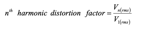
The individual harmonic distortion factor:
Total Harmonic Distortion
The Total Harmonic Distortion (THD) is an indicator of the distortion of a signal. It is widely used in electrical engineering and Harmonic management in particular. The THD is defined as:
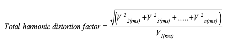
THD is the ratio of the RMS value of all the harmonic components of the signal, to the fundamental.
Note that THD can exceed 1 and is generally expressed as a percentage.
-
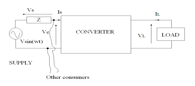
Load and supply harmonics
• Rectifier dc voltage contains harmonics
• Lowest order is p (pulse number)
• Harmonics of np also exist
• Controlled rectifier has higher harmonics content vs. uncontrolled
Load harmonic voltage leads to harmonic current
Level current is not always justified as there is no infinite inductance
Ripple in load,
Even harmonics, (n * 50 Hz), n=2,4,…
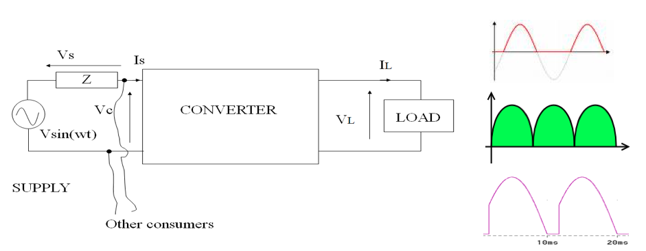
● At the supply side:
● Sinusoidal voltage with power flow to load
● Non-sinusoidal current will be drawn
- load transmits harmonic power back to supply
- Load is harmonic generator
● Even harmonics are cancelled but, odd harmonics are existing
● Non-sinusoidal current will be drawn
● Vs voltage drop across supply impedance
● Vs depends on the harmonic contents
● Vc for other customers will be non-sinusoidal at PCC
- Regulation of harmonics at PCC
- Multiple- harmonics
- Sub-harmonics (flickers)
-
Electro-magnetic interference
● Switching high current and voltages, generate unwanted signals,
● Affects other electronics systems
● EMI known as Radio Frequency Interference (RFI) is quite severe,
- System acts as high frequency transmitting antenna
- Propagate through cables
- Low voltage gate control circuit can be affected as well● Power and communication cables must be isolated
-
Electromagnetic compatibility (EMC)
What is EMC?
● A device that does not cause intolerable interference to other devices or itself (e.g. control circuit affected by switching)
● Is immune to disturbance from EMI
Three methods for realization of EMC:
● Source of EMI – reduce source emission
● Media through it is transmitted- block propagation path
● Receptor – make it less susceptibleCategories of disturbance
● Conducted via leads to supply- limited by using filters
● Radiated through the air as HF radiation- limited by screening, earthing, PCB layout
International / European Standards
● BSI (UK), FCC (USA), VDE (Germany), EN (EU)
● Define legal limits (volt and frequency) -
Control/mitigation of harmonics
● Harmonics can be mitigated by:
1. Controlling generation within converter:
- e.g. PWM to minimise low frequency harmonics
- High frequency switching harmonics (from carrier signal) can be easily filtered with a low pass filter since they are at the high end of the spectrum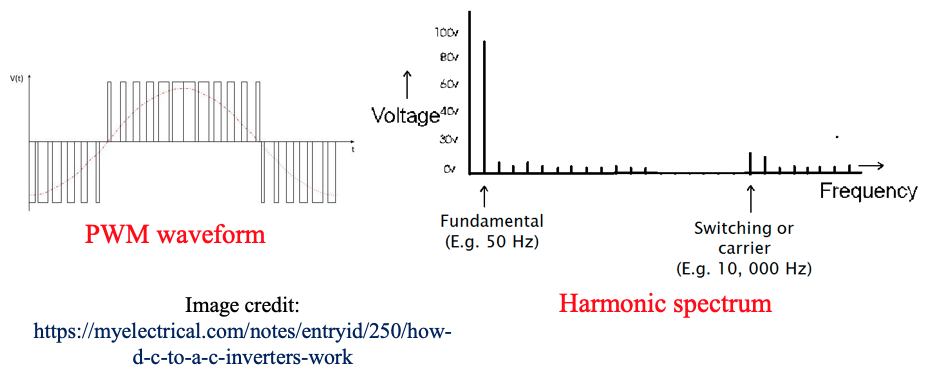
2. By using filters:
- Smoothing/filters on rectifier outputs
- Low pass filters on inverters
- Harmonic line traps
- Screening
● We will study different types of harmonic filters:
-Rectifier output smoothing
-Inverter output filtering
-AC line filter
-Radio interference suppression -
Types of filters

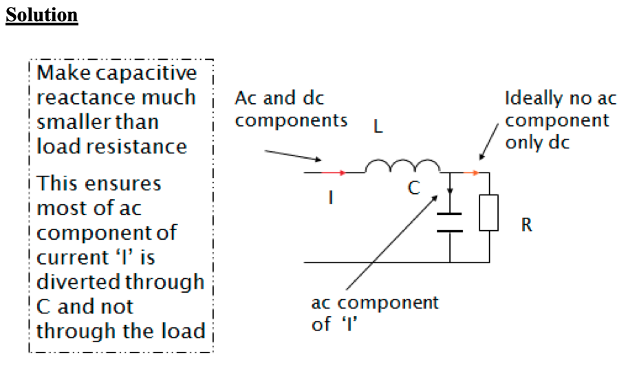
1. Rectifier output smoothing
Inductance only: similar to inductive load, smooths current
Capacitance only: charging & discharging, RC time constant
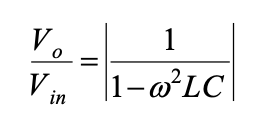
Combination: C maintains voltage, L smooths current. Higher-order harmonics are attenuated by the filter transfer function:
2. Inverter output filtering
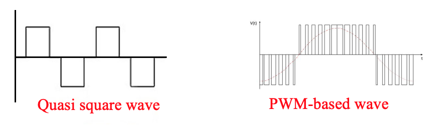
● Inverter output, quasi-square, PWM
● Typical THD =5%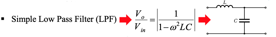
● If inverter designed to eliminate low order, LPF adequate for higher order elimination
3. AC line filter
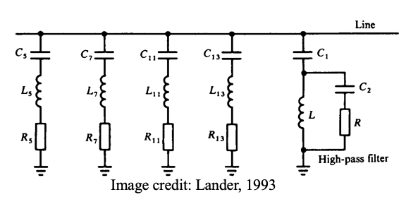
● Each branch is tuned for specific harmonic order
● Losses at fundamental may be significant
● Frequency drifts from nominal must be taken into account during design, or
● Use auto tuned filter

4. Radio Interference Suppression
● Switches give rise to mains-borne harmonics in RF range
● RFI with communication system. Originates from:
- Switches- limited by screening
- Load equipment- limited by screening
- Radiation from the supply lines- limited by filter
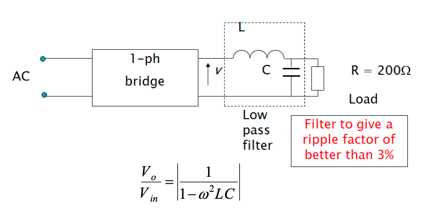
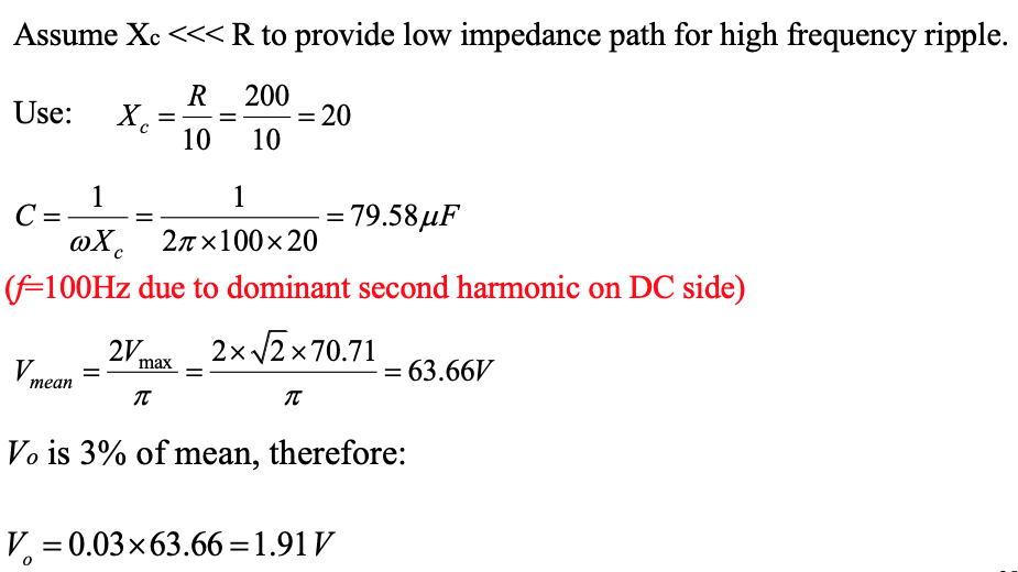
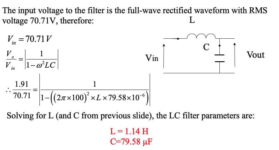
Example on filter design
A single-phase 50 Hz bridge rectifier is fed at 70.71 V (rms). The load is a resistance of 200 Ohms. Design an LC filter for the purpose of providing a maximum ripple factor of 3% ( explain any assumptions made ).
-
Check your understanding by answering the following:
- Explain what is meant by non-linear loads highlighting their impact in creating harmonic currents and voltages
- Show how Fourier Theorem is used to represent a non-sinusoidal periodic function.
- Briefly explain what is meant by the term “harmonic of order h”.
- Define the term “Total Harmonic Distortion”.
- Discuss the impact of using rectifiers on harmonics at supply and load sides.
- Explain what is meant by electromagnetic compatibility and state THREE methods of realizing it.
- Mention TWO categories of disturbance that EMC systems and how these disturbances can be limited
- Explain how the impact of harmonics can be mitigated in power electronic circuits. Include in your answer mention about PWM techniques to mitigate harmonics and different types of filter circuits.
- A square wave has:
(i) Odd harmonics only
(ii) Even harmonics only
(iii) Odd and even harmonics
(iv) Odd harmonics and DC component
Select only ONE correct answer.- Determine whether these statements are TRUE or FALSE:
(i) Harmonics do not affect power system losses nor power bills of end-users
(ii) Total power generated by a harmonic signal is due to sum of powers at each harmonic.
(iii) The RMS voltage of the harmonic signal is achieved by the sum of the square individual harmonic RMS voltages
(iv) In AC line filters, each branch is tuned for a specific harmonic order