-
HV Generation and Testing
- Learning objectives
• To appreciate the importance of HV generation, measurement and testing
• To learn how HVAC, HVDA and HV impulse are generated for HV testing
• To understand how HV voltage and currents can be measured, and how the measurement circuits are configured
• To understand how HV equipment and materials are tested for various purposes
• To analyse the results of HV testing
• To appreciate the procedures of commissioning new installations to power systems. - Learning objectives
-
HV Generation
2.1 HV A.C. generation
It is necessary to carry out lab tests on HV plant items or insulation specimen before the design and commissioning, so there is always a market place for the HV generation. In an AC network the equipment is continuously subjected to full power frequency voltage. The equipment should therefore be able to withstand power normal frequency voltage, allowing for some overvoltage.
There are basic ways of A.C. voltage generations: high voltage transformers and resonant circuit.
In a high voltage laboratory the test transformers steps up the voltage from a lower voltage (230 V or 11 kV) to the desired voltage level. All laboratory tests are single phase and the low voltage side of the transformer is supplied via a regulating transformer to be able to adjust the magnitude of the output high voltage. A typical AC high voltage set-up is shown in Fig. 1. Note that test transformers can be used in cascade connections.
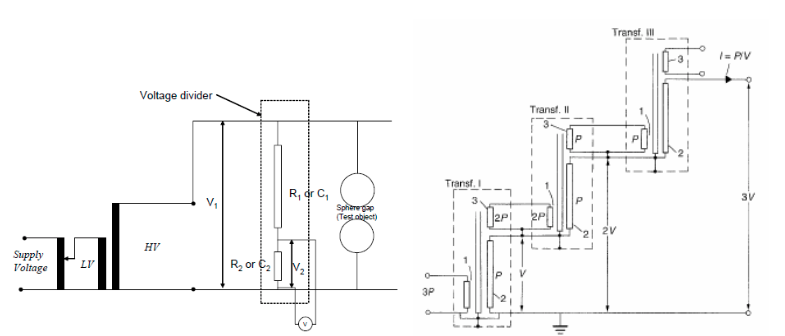
Figure 1 A typical AC test transformer and its connections (left); typical cascaded connections (right).
Both series and parallel resonant test systems are employed. Figure 2 below shows a typical series, resonant test circuit, where the test sample is connected in series with the HV reactor, and a parallel resonant test circuit.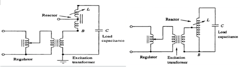
Figure 2 A series (left), and a parallel (right) resonant test circuit.
2.2. HV direct current (DC)
DC tests are used mainly to do "pressure tests" on high voltage cables. Although the cables operate with AC, AC testing is not practical. The high capacitance of the cables necessitates AC test sets with a high kVA rating to be able to supply the capacitive current. In the case of DC, once the cable is charged, only the losses have to be supplied. Figure 3 below shows a typical DC test circuit.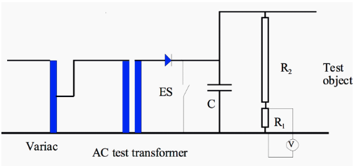
Fig.3 Typical circuit for DC test
Design features to be considered include:
• Output voltage and duty
• Input/output voltages
• Output polarity
• Line and load regulation
• Efficiency
• Life time
• Ripple
• Stored energy
• Metering and control (remote programming)
• Protection and transient response
• RFI (radio frequency interference)
• Earthing
Among the factors, voltage ripple, regulation, stored energy and protection and transient response are mutually inseparable, all relating to the transformer/rectifier/capacitor sizes. There are big advantages to have small capacitor rating for given values of required voltage ripples, as there is less stored energy, and thus safer operating environment.Example: for a given 10kV supply with a load current of 10mA and output ripple voltage (dV) of 1 V(pk to pk). At 50Hz, the half cycle period (dt = 1/100 secs).
I = C dv/dt
10 x 10-3 = C x100 (dt = 1/100 secs)
C=100 μF
At 30 kHz, C=0.167 μF.
Control and protection are much easier, in addition to space saving and energy reduction. Safety circuit can collapse the output almost instantly when a load short circuit occurs.
2.3. Generation of high voltage impulse
Power systems are also subjected to overvoltage pulses, due to lightning and switching. These pulses can take on many different wave shapes. Standard impulse wave for HV plant testing has been defined as shown in Fig. 4. The actual definition is more precise, but for lightning impulses, T1 is 1.2 μs and T2 is 50 μs. The standard lightning impulse is described as a 1.2/ 50μs wave. The standard switching impulse is a 250/ 2500 μs wave.
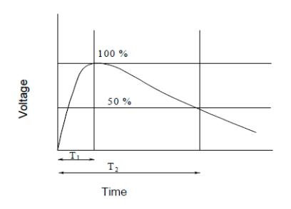
Fig.4 Definition of impulse waveform
A typical generation circuit, such as the Marx multi-stage impulse generator, consists of:
• The power input, often a DC source,
• The storage device, often a capacitor
• A fast switch such as a triggered spark gap
• Wave shaping network
• Load
-
Measurement of High Voltage
In high voltage, due to safety reasons, the meters cannot be connected directly to the high voltage conductors. It is therefore necessary to use equipment to scale down the voltage signal to a safe value that can be displayed on instruments. On the power system, voltage and capacitive voltage transformers are used, while other techniques are used in the laboratory. Obviously, accuracy of the whole system is of the utmost importance.
HV measurement techniques include:• DC measurement: sphere gap, electrostatic voltmeter, series resistance micrometer and resistance divider
• AC measurement: sphere gap, electrostatic meter, series impedance ammeters, potential transformer and resistance or capacitance divider
• Impulse or high frequency measurement: sphere gap, peak meter and potential dividers with oscilloscope
3.1 Sphere gap for voltage measurement
According to Paschen’s Law, there exists a relationship between the flashover voltage, the gap length and the gas density. International standards have been drawn up to relate the gap length with flashover voltage. Provision has been made to correct for air pressure and temperature. Usually an accuracy of about 3 % can be obtained. Specifications such as IEC 52-1960 and BS358 contains tables for various sphere diameters and gap sizes.
Fig 5 shows a schematic and a picture of the real world sphere gap. The relationship of the voltage to be measured and the length of the gap can be found from BS 358.
Fig 5 Schematic diagram and picture of sphere gap for high voltage measurement.
3.2 Voltage divider
Fig 6 below shows the principle of a voltage divider, where the impedance values determine the proportion of the voltage V2 over V1. For DC measurement, the impedances take the form of resistors. Both resistors and capacitors can be used for AC and impulse measurement.
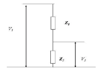
Fig 6 The principle of voltage divider for high voltage measurement.
Clearly,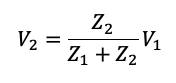
For capacitive and resistive dividers.
Stray capacitance of resistors may affect accuracy in measurements.
3.3 Electrostatic voltmeters
Electrostatic voltmeters rely on the Coulomb force of attraction between two electrodes that have a potential difference between them. Such a measuring system has the advantage that the measurement relies on the laws of physics. In addition, the input impedance of the meter is capacitive. Especially in the case of DC, the meter therefore does not load the measured circuit.
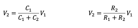
Attractive force between electrodes of a parallel plate condenser is: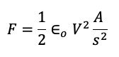
Where, A is the electrode area and s the separation between plates. When one of the electrodes is allowed to move, the force on it can be measured.
3.4 Voltage measurement with transformer ratios.
Instrument transformers can be used for HV measurement. The principle is no different from traditional transformers. Current transformers and voltage or potential transformers are common plant items in real world power systems.
• HV Measurement in practical applications–the rms value of a periodical function can be expressed in terms of the Fourier coefficients
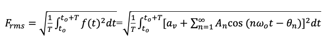
The expression can be simplified as:
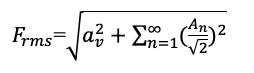
For example:
V=10+20 cos(ωo t-θ1 )+30 cos(2ωo t-θ2 )+10 cos(3ωo t-θ3 )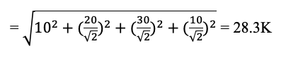
-
HV Testing
See reference book:
High Voltage engineering and testing: Ryan: 2001
High Voltage Engineer, J.R. Lucas ---- http://prof.rohan.lucas.lk/images/notes/H%20Voltage/HV_Chap9.pdf -
Power plant commissioning management
New plant items are often connected to power systems. Strict procedures of commissioning and management are required in order to guarantee safety and reliability. Power plant commissioning include activities which demonstrate that an item of equipment is acceptable for service, including inspections, off-load and on-load commissioning tests
The objectives include verifying that equipment has not been damaged, correctly installed, perform to specification, and to obtaining data for comparison with future.
The contractual responsibilities are clearly defined in advance. The tables below provide an example.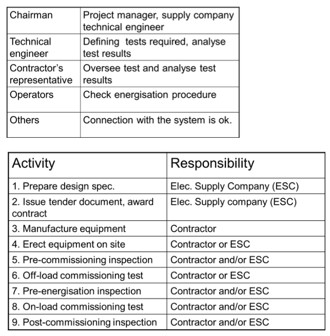
The program of commissioning includes the following items.
• Pre-commissioning inspection
• Off-load commissioning test programme
• Pre-energisation inspection
• Energisation and on-load commissioning tests
• Post-commissioning inspection