-
Dr Azmy Gowaid
School of Computing, Engineering and Built Environment
Glasgow Caledonian University
Email: azmy.gowaid@gcal.ac.uk
Salameh, Z. (2014). Renewable energy system design.
Waltham, Massachusetts: Academic Press. (Available online)
Chapter 2 -
Photovoltaic Cell Physics
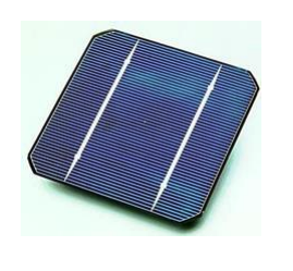
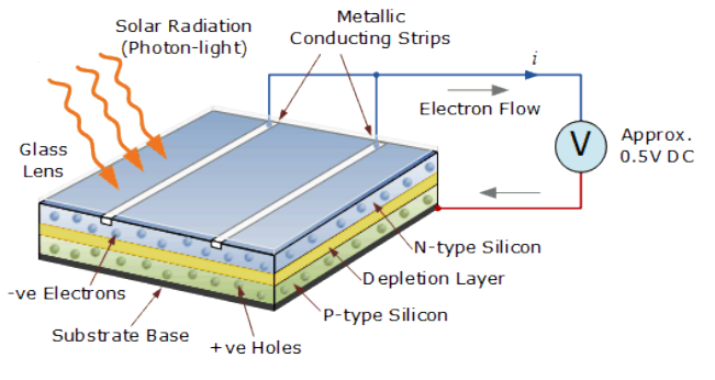
- Photovoltaic cell is an electrical device that converts the energy of light directly into electricity by the photovoltaic effect.
- It is a form of P-N junction created by silicon layers with different doping materials (creating free electrons and positive holes)
- Solar radiation falling on the cell creates an electric field and potential difference between the two layers
- Current flows in an external circuit connected between top metallic conducting array and base plate
Photovoltaic Cell Types
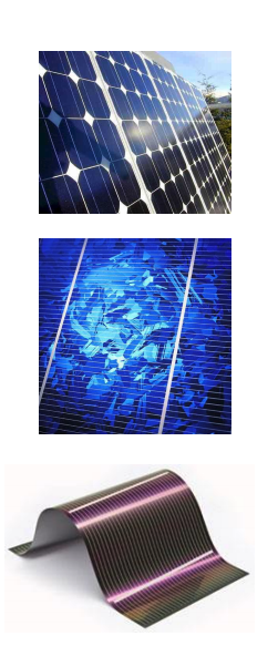
Monocrystalline PV cell (single-crystal silicon):
- Most efficient commercially available PV cell
- Cell efficiency is about 20 - 23%
- Module efficiency 14 - 20%
- Most expensive to manufacture
Multicrystalline PV cell (Polycrystalline silicon):
- Cell efficiency is about 17 - 20%
- Module efficiency 12 - 15%
- Less expensive to manufacture
Multicrystalline PV cell (Polycrystalline silicon):
- Easily deposited on a wide range of surface types
- Least efficient, around 4 - 8% module efficiency
- Inexpensive to make (cheapest cost per Watt)
Photovoltaic Solar Arrays
- A typical PV cell produces approximately 0.5-0.6 V and a current that very much depends on the intensity of the sunlight and the area of the cell. Typical current at maximum power can be up to 6-8 A, leading to power output of 4-5W.
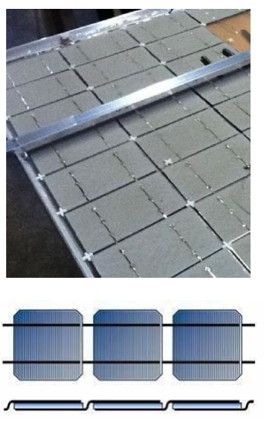
- To get more usable values of voltage and current, PV cells are connected in series to increase voltage (forming a module/panel)
- Modules/panels can be connected in series to increase voltage output (forming a string)
- Strings connected in parallel to increase current output (forming an array).

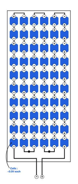
- Come in variety of designs. An example commercially available Solar PV module is composed of 72 cells (6x12) with a maximum output of about 350W.
- PV cells connected in series in the panel and the output voltage is about 36V
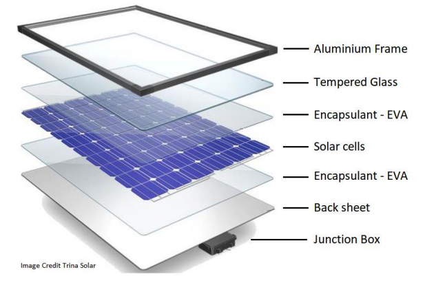
Photovoltaic Modules

- Come in variety of designs. An example commercially available Solar PV module is composed of 72 cells (6x12) with a maximum output of about 350W.
- PV cells connected in series in the panel and the output voltage is about 36V

Photovoltaic Modules (Junction box)

- The positive and negative terminals of the module are normally obtained at the back through a junction box in which ‘bypass/blocking diodes’ are placed.
- In larger systems modules are typically connected by 20A 600V MC4 connectors which can be disconnected only using a tool (to avoid accidental disconnection).
- MC4 connectors are of high Ingress Protection rating (IP68) for high protection against dust and water
- PV Panel frame is grounded.
Photovoltaic Strings
- PV strings can be long in large PV solar farms
- In high power PV systems, series connection of modules in long strings (minimizing parallel connections) is preferred to reduce current and losses.
- That’s why string voltage can reach 600V across string terminals. Larger strings can sum up to 1500V terminal voltage.
- Therefore, cables and MC4 connectors insulation can be rated up to 1500V with respect to ground (panel frame).

PV Cell Electrical Characteristics
Photovoltaic Cell I-V Curve
- The most important performance descriptor for a photovoltaic device (i.e., cell, module, panel, and array) is its current–voltage (I–V) characteristic.
- For a given irradiance, the operating voltage and current vary with load.
- The maximum current is called short-circuit current (Isc) corresponding to zero voltage at the cell terminals (short circuit)
- The maximum operating voltage is called the open-circuit voltage and corresponds to zero current flow (open circuit)

Image by Salameh, Z. “Renewable energy System Design”, chapter 2
Photovoltaic Cell operating point
- When a resistive load is connected to a PV cell, operating point current and voltage is decided by intersection of the I–V characteristics curve of the PV cell and the I–V characteristics of the load curve, V=IR.
- The slope of the load curve 1/R and the operating point will depend on the value of R.
- Each slope represents a certain resistance.
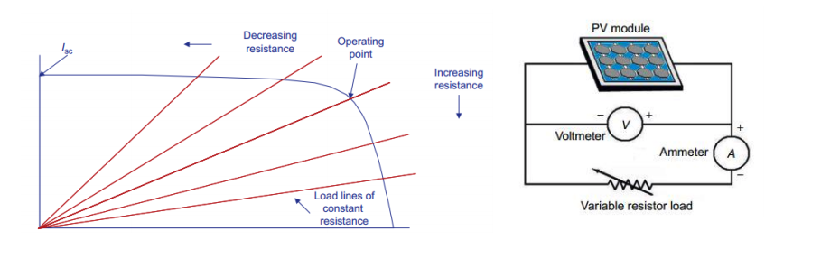
Image by Salameh, Z. “Renewable energy System Design”, chapter 2
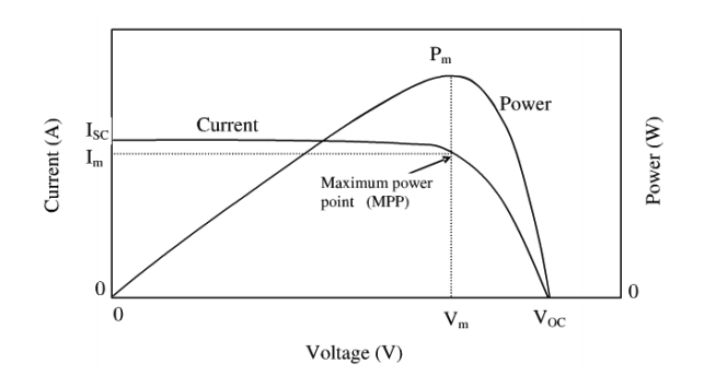
Photovoltaic Cell P-V Curve
- The operating point is subject to the (equivalent) load resistance and is characterized by I < Isc and V < Voc.
- PV Cell power-voltage (P-V) curve can also be plotted using P=VI
- Maximum power (Pm = VmIm) occurs at a point corresponding to a current value Im < Isc and a terminal voltage Vm < Voc
- Actual power output will depend on the loading (load curve slope).
PV cell vs PV module
- A PV panel is normally made of identical/similar cells
- Being connected all in series, panel I-V and P-V curves are similar to the PV cell curves with difference in power and voltage values where:
Pm_panel = n x Pm_cell , Voc_panel = n x Voc_cell , Isc_panel = Isc_cell
For a standard panel (72 cells):
Pm_panel ≈ 350W , Voc_panel = 72*0.6 ≈ 43V Isc_panel ≈ 8ASo, the photovoltaic module/panel has the same I-V and P-V curves as in a photovoltaic cell but scaled up to module values.

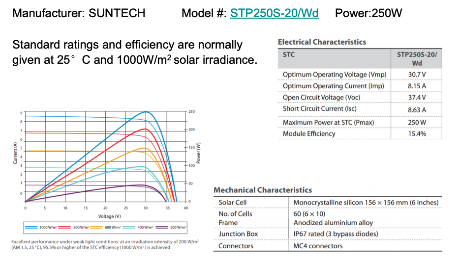
Impact of solar irradiance and temperature
As the solar irradiance (the light intensity) increases:
- Isc increases linearly
- Voc increases logarithmically
- The maximum power Pm increases
In general, as the temperature increases:
- Isc slightly increases
- Voc decreases
- The maximum power Pm decreases
How cell/panel datasheets look like?
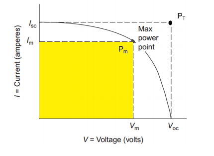
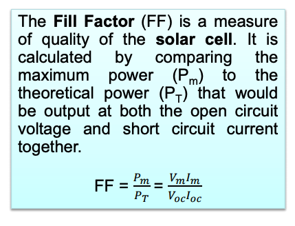
Efficiency and Fill Factor (FF)
- The efficiency of a solar cell is given as as η = Pout/Pin where Pin = S x Ac (S is irradiance and Ac is area of the cell)
- Another important parameter of a PV cell is called the Fill Factor (FF)
- FF is a measure of how much actual power can be produced from the cell compared to the open circuit/short circuit ratings
Illustrative Example
A photovoltaic module has the following parameters:
Isc = 2.5A, Voc = 21V, Vm = 16.5V, Im = 2.2A (given at standard conditions of irradiance and temperature).
The length of the module is L = 90.6 cm and the width of the module is W = 41.2 cm
a) Calculate the fill factor (FF)
b) The module is connected to a variable resistive load at an irradiance of S = 900W/m2. The voltage across the resistance is V = 17.5V and the current flowing in the resistance is I = 1.4A. Calculate the module efficiency,
- Click to view the solution

-
Connection of PV Devices
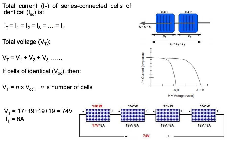
Series Connections of Similar PV Devices
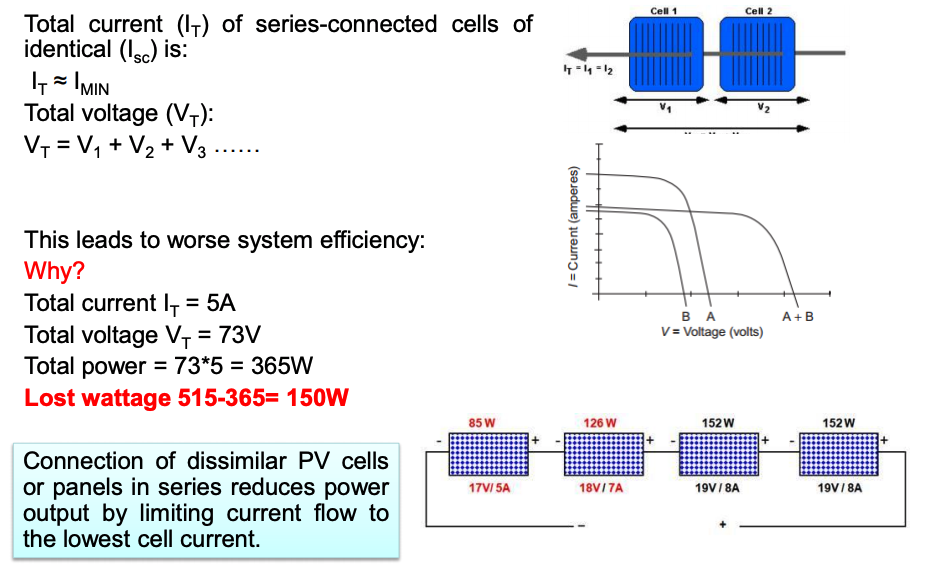
Series Connections of Dissimilar PV Devices
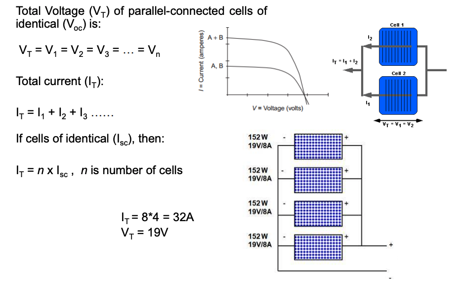
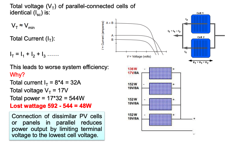
Parallel Connections of Similar PV Devices
-
Blocking and Bypass Diodes
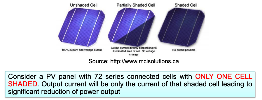
Shading Effects
- In real PV systems, normally similar cells and panels are used.
- Mismatch between cells arises due to operating conditions.
- The most common source of mismatch is partial or full shading of some cells or modules.
- Shading is a serious issue that requires protection of cells.
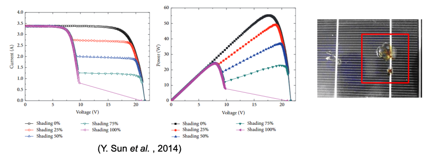
See this video to see the impact of usual levels of shading on PV panel output
- In addition to significant reduction of power output, shading can lead to damage of shaded cells/panels.
- The shaded cells may get reverse biased, acting as loads, draining power from fully illuminated cells. If the system is not appropriately protected, hotspot problems can arise and in several cases, the cell/panel can be irreversibly damaged.
Bypass diodes
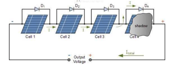
- They are used in parallel with either a single or a number of photovoltaic solar cells to bypass current flow through the cell(s) in case of shading or to avoid damage and power reduction.
- Typically one, two, or three bypass diodes are connected in the junction box of the PV panel
- If one bypass diode connected, shading of one cell bypasses the whole panel.
- If more than one bypass diode per panel, each diode bypasses a section of the panel if one or more of its cells are shaded.
Blocking diodes
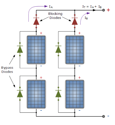
- In A PV array, a blocking diode is required in each ‘series string’ of PV panels
- It is to be connected between the string and regulator/battery, to prevent current flowing back through the modules when the modules are shaded or during darkness
- It is usual to fit the blocking diode into the positive output inside the junction box of the solar module placed at the positive end of each string of panels
- Blocking and bypass diodes need to be rated for suitable current levels (not less than protected PV device current)
-
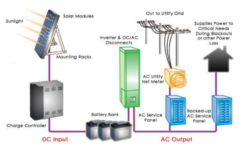
Components of a PV Solar System
Generic structure (residential system)
Generic structure (Utility scale PV power station)

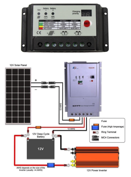
Charge Controller (Voltage Regulator)
- Present in PV systems with energy storage (battery packs)
- Solar charge controllers regulate the energy flowing from the PV array and transfer it directly to the batteries as a DC-coupled system
- Maximum Power Point Tracking (MPPT) is implemented within the solar charge controller to detect and determine the maximum power point voltage and current that can be provided by the PV panel.
- Various MPPT algorithms can be used to extract maximum power output under dynamically varying conditions of temperature, cell shading, and solar irradiance.
Maximum Power Point Tracking (MPPT)
Many algorithms have been devised to control the MPPT. Three of the most commonly used techniques are:
1- Perturb-and-observe
2- Incremental conductance algorithm
3- Power slopeA DC/DC converter controls PV array voltage to control the operating point.
The Perturb-and-Observe method:
- Operates by periodically perturbing the array terminal voltage and comparing the PV output power with that of the previous perturbation cycle.
- If the voltage perturbation results in an increase in PV system output power, the subsequent perturbation is made in the same direction.
- Conversely, if the voltage perturbation results in a decrease in PV output power, the succeeding perturbation is made in the opposite direction.
- Clearly, if the voltage perturbation does not change the PV output power, no change is made in the following cycle.
Perturb and Observe MPPT method

Power slope (Hill Climbing) MPPT method
- The power slope method uses the power slope dP/dV directly to find the maximum power point.
- Both the PV array output current and the voltage are sensed at consecutive time intervals so that the power slope can be calculated. The power slope is calculated as follows:
dP/dV = [P(current) – P(previous)/ V(current) – V(previous)]
- If the output voltage of the PV array is increasing (dV>0) and dP is calculated to be positive, then the power slope is positive and voltage is increased one small step by the DC/DC converter
- If dP is calculated to be negative, then the power slope is negative and the direction of voltage change would need to be reversed by decreasing PV array voltage by a small step by the DC/DC converter.
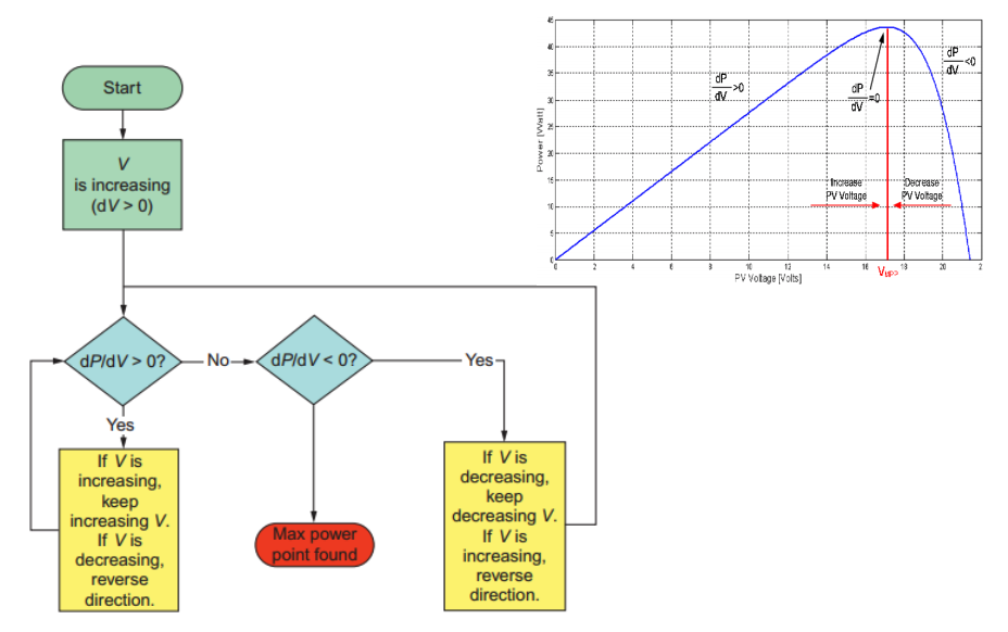
Image by Salameh, Z. “Renewable energy System Design”, chapter 2
Power Inverter
- It is an electrical converter which converts the variable DC output of PV solar system into a utility frequency alternating current (AC) that can be fed into a commercial electrical grid or used by a local, off-grid electrical network.
- In systems without batteries/solar charge controllers, the inverter is responsible of controlling the voltage of the PV system for maximum power point tracking operation.
- In large PV power stations, central inverter, and inverter per string, or micro-inverters (inverter per panel) are possible.

-
-