-
Email: Dong.Chen@gcu.ac.uk
Please read
Chapter 3, 6 and 7, Bollen, Math H. J., etl . Integration of distributed generation in the power system,2011
Chapter 4, Jenkins, N , etl. Distributed generation, 2010Unit Overview
In this unit, you will learn :
- How DG may affect the overcurrent protections in a distribution network
- The concept of islanding
- How the DG may affect the power quality
- How the shunt compensation for DG may cause resonance in a distribution network
-
DG and Current Protections in Distribution Network
Introduction to Protection of Distribution Power System
For an ideal power system protective system:
- It should ideally use local measurements only
- Each relay (what is a relay?) should be able to distinguish a fault anda non-fault situation.
- All the relays should be able to distinguish non-fault and fault condition in all locations and faulty conditions.
- The relays should further be able to provide backup for all downstream relays.
- For the above requirement is already demanding for a power system with uni-power flow directions, the possible fault current contribution from DGs may make the protection more complex.
Traditional protection system for distribution networks:
- Uni-directional power flows:
– Assume power flows from the grid supply point to the downstream LV network
– Simplify the configuration of voltage regulation as the voltage profile is only affected by the loads and connections
– Simplify the current protections since the fault current direction will be largely unchanged
Traditional Protection System for Distribution Networks
In a conventional distribution network without any DGS, protection is based on overcurrent relay
- The fault current will not flow into the unaffected branches as it is unidirectional in a radial network.
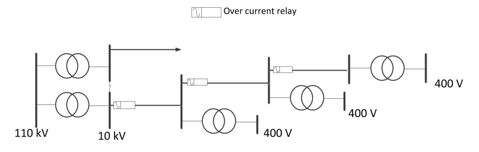
The above diagram illustrate a typical over current protection scheme in a distribution network where discrimination is achieved by the magnitude of fault currents. In this DG-free system:
- The fault current will always flowing from the upper stream and will never flowing from or into the parallel branches in a radial network
- The upper stream fault will not be detected by the down stream
- Relays can be configured according to the magnitude of the fault current
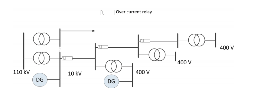
The Inclusion of DG to an Established Distribution Network with Current Protections:
- The fault current may increase or decrease depending on its location and the location of generators
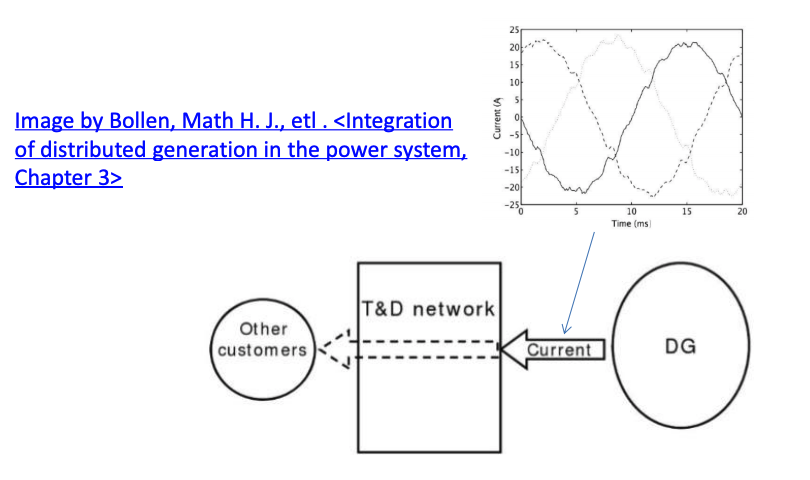
- The DG, as illustrated below, may provide the flows of fault current to which ever direction the voltage is lower, including upstream, downstream or the parallel branches. This distribution of fault current is not expected at the time of designing the original protection system.
- Unexpected fault current distribution may result in mal-functioning of the entire protection systems.
Major Concerns of Protection - DG
Before installing DG into distribution network, from the network protection point of view, the following aspects should be considered:
- Protection of the DG equipment from internal faults
- Protection of the faulted distribution network from fault current supplied by the DG
- Anti-islanding or loss-of-mains protection
- Impact of DG on existing distribution system protection
Internal fault protection - DG
- Protection of the DG equipment from internal faults:
– It is probably the most straightforward aspect.
– Techniques used to protect the DG itself is adequate.
– Makes trivial difference from grid side protection.
– It does not really affect the protections of the external network provided the faulty behaviour is known
Protection of the Distribution Network from Fault Current Supplied by the DG
- The protection against the DG fault current is a difficult issue, especially when the DG can contribute a prolonged fault current, which was expected from original system design.
- The fault current contribution of DG varies according to type and size: The most commonly seen types are synchronous generator, induction generator, power electronics based generation:
– Induction generator does not provide sustained fault current since there isno independent field excitation.
– Synchronous generator will provide a sustained high fault current given the field excitation unchanged during the fault.
– Power electronics converter normally does not provide sustained fault current but transient behaviour depends on control strategy.- The introduction of high DG fault current can significantly interfere the protection functions.
Example : Interference of DG upon Overcurrent Protection - 1
As shown in the right, the upstream network is from the main grid. Two feeder Circuit Breakers, CB 1 and CB 2 are located at one end of each feeder.
A new Synchronous Machine(SM) based DG is installed in an established distribution network. Suppose the fault occurs at the feeder of CB 2, as shown.
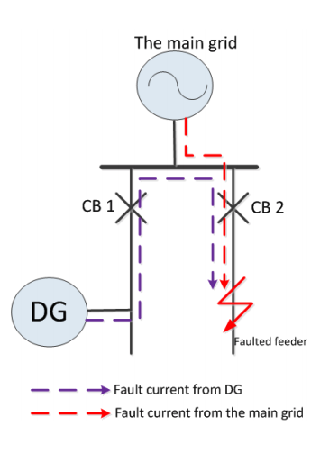
The interference with the protection selectivity:
- For a correct operation of the protection, CB 2 should open and CB 1 will not.
- The contribution of the synchronous machine to the fault may be mistaken as a downstream fault of CB 1
- Using conventional O/C protection, the result would be a mal-trip of breaker CB 1 and the downstream of CB 1 is mistakenly tripped from the upstream network. If there is other power sources, an unnecessary outage will happen at the downstream of CB 1.
Example: Interference of DG upon Overcurrent Protection - 2
The interference with the ratings of the protective device:
- The total fault current through breaker CB 2 will be the sum of the fault currents provided by the main grid and the DG.
- The prospected current will be higher than without the DG.
- The prospected fault current may exceed the rating of the switchgear CB 2.
- To effectively protect the feeder, CB 2 has to be replaced with larger rating if the prospected fault current from the DG is significant.
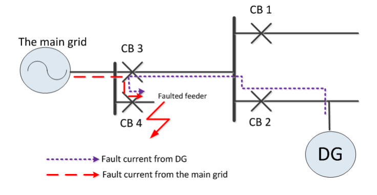
Example: Interference of DG upon Overcurrent Protection - Upstream
- The problem may also occur for faults at a higher voltage level.
- As is shown below, when a fault happens at the feeder of CB 4, DG will contribute fault current to the fault location as well as the grid.
- As a result, CB2 and CB3 may operate mistakenly causing outage for the entire down stream area.
Methods to Neutralize the Protection Issue brought by DG - 1
The methods to neutralize the protection hazards brought by DG can be divided into 2 types: DG side approach and the grid side approach.
- DG side approach:
This to mitigate the DG impact during a fault from the DG side
– DG fault current control: to minimize the fault current so DG will not affect the judgement of the network relays
• Regulating the fault current using Power Electronics control technology
• Limiting the fault current using non-PE technology (fault limiter)
– Dedicated fast protections for the generator so the fault is cleared before the network relays responds
– DG side schemes are should be ideally plug-and-play so DGs do not affect the rest of the power network, which is challenging but promising with modern PE interfaced DGs
Methods to Neutralize the Protection Issue brought by DG - 2
- Grid side approach:
This is to improve the protection capability from the Grid side.
– Upgrade of the network protections by reconfiguration of the relays
– Using advanced protection technique in distribution network: directional protection, differential protection, etc., so the fault current fault nonupstream side can be discriminated
– Increase the rating of switch gears if necessary -
DG and Islanding
When a power network is energized without the connection to the main grid, an island is created. This is particularly possible when DGs are in place but unlikely happen to a passive distribution network.
- An island has to be either detected immediately or be well-planned before it occurs
- Islanding is also known as Loss-of-main
– An unintentional islanding may lead to electrical hazards for maintenance personnel
– The island frequency will quickly deviate from the main network causing phase shift; in case of a reconnection, it can cause excessive current spike.
– The fault level within the island will be reduced and if a fault were to develop, the resulting current might be insufficient to operate the protective devices.- An anti-islanding relay is essential to detect unplanned islanding and trip the source
Basic Methods of Islanding Protections
Principles:
- Based on the assumption that once an unplanned islanding happens, the power generation will not be able to meet the original loads exactly.
- Such unbalance of power will result in a deviation of certain electrical quantities: frequency, voltage, etc.
- Once a certain electrical quantity comes out of its normal range, the generator is tripped. Also known as passive detection method
Types of the passive anti-islanding protection methods:
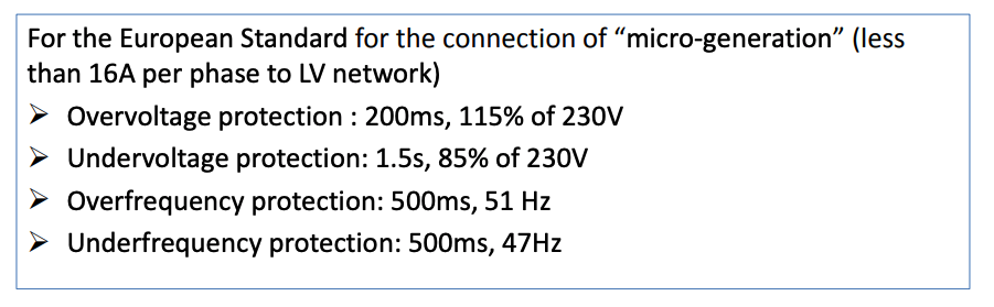
- Over-voltage protection
- Under-voltage protection
- Over-frequency protection
- Under-frequency protection
Typical Passive Anti-islanding Detection Method
- E.g. a predefined operational frequency range is between 45-55 Hz; once the detected frequency reached 55.1 Hz, the islanding is “detected”.
- The drawback is obvious – possible incorrect detections: other disturbance such as large load switching or some remote fault can also lead to large voltage or frequency variations.
- It is quite difficult to define voltage/frequency for the protections.
- To mitigate the drawback, delayed detection is introduced.
1. The introduction of delay does help to distinguish islanding from other transient disturbances, but it still cannot exclude “mal-detection” completely.
2. Besides, it slows done the detection.
Anti-islanding: ROCOF
The frequency of a utility network is mainly maintained by the inertias of the rotors with in the generators of those power plants. The loss of main also mean the loss of the inertias, hence the loss of maintaining the frequency. Given this,
- Rate of change of frequency (ROCOF) is measured to detect the loss of inertia in a distribution network.
- This relay will trip the generator in case the frequency changes more than a certain set point within a certain amount of time.
- Thus the adjustment is done in Hz per second [Hz/s] .
- The frequency change appears because the load situation on the generator will change suddenly in case the voltage changes due to the loss of mains.
- This load change causes a change in the instantaneous voltage profile hence a frequency change.
Rate of change of frequency (ROCOF)
Condition: if the DG is based on synchronous generator and the prospected island is created by the DG.
The rate of change of frequency following an islanding event is directly proportional to the amount of active power imbalance between local load and the generator output.
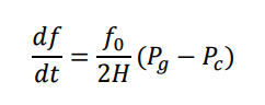
where f0 is the power system frequency and H is the inertia of the island; 𝑃𝑔 the total power generation; 𝑃𝑐 the total power consumption.
Islanding Detection using Phase shift
- This protection is for the internal protection of a distributed synchronous generator itself
- Principle: during normal operation, the frequency and voltage phase angle is predictable according to constant frequency
- This relay will trip the breaker in case it detects a phase shift in the generator voltage.
– If a zero crossing occurs some degrees earlier or later than expected.
– Thus the adjustment is done in degrees.- Depends on the change of the generator frequency.
– This shift is the integration of frequency deviation.
– If this vector shift is larger than a certain set point to a preset condition (6 degree difference for UK) the relay will trip.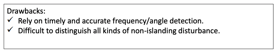
Electro-magnetic Resonance during Island Operation
- An island operation may create RLC circuit with a natural resonance frequency other than grid-connected condition.
- Considering a synchronous generator is creating a islanding operation.
The EMF of the synchronous machine is supplying one feeder with an Impedance of Zgen.- With a capacitance of C at the feeder, the resonance can occur at the frequency of
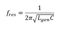
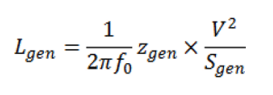
where, for a generator with an apparent rating Sgen and per unit impedance Zgen, the inductance is
Example – Possible Resonance during Islanding Operation - 1
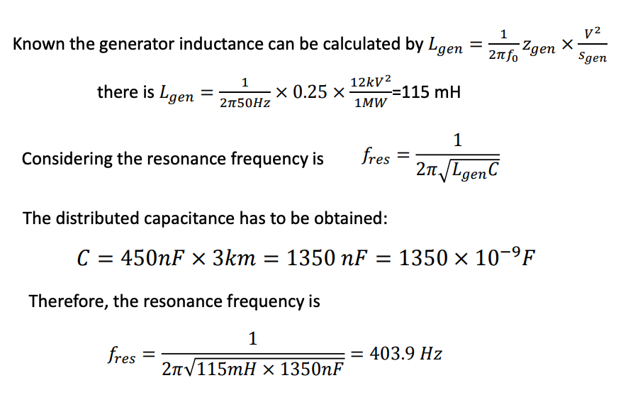
A synchronous generator is supplying a 12kV feeder during an islanding operation. The power rating of the generator is 1 MW and the total equivalent impedance between the emf to the feeder is 0.25 p.u. over a distance of 3 km. The distributed capacitance along the distribution line is 450 nF/km.
Calculate the natural resonance frequency in such system. (assume the impedance is purely inductive)
Example – Possible Resonance during Islanding Operation - 2
-
DG and Power Quality
Introduction to Power Quality Issue Brought about by DGs
- The ideal voltage and current:
– pure sine waves: harmonics-free (what are harmonics? video)
– Constant at nominal frequency
– Constant magnitude within desirable ranges
– In phase (same frequency, same magnitude, 120 degree from each other in the right sequence)- Power quality concerns the electrical interaction between the network and the end users. Watch what an industry says.
- Both the grid and the customer can affect the power quality
Please read Chapter 6 Bollen, Math H. J., etl . Integration of distributed generation in the power system,2011
Power Quality – Voltage
- Voltage profile is mainly determined by the grid and by events in the grid
- Significant end user activity can also affect the voltage profile
- The impact of voltage disturbance
(watch what voltage disturbances may look like video)
– The disturbances include voltage dips, overvoltages, harmonics, unbalance and voltage fluctuations, etc.
– Voltage disturbances may apply extra voltage to the nominal to power equipment hence a reduction of equipment lifetime
– The transient voltage and its consequent currents may reach the threshold of some protections causing erroneous protective operation
– For the most severe case, a voltage disturbance and consequent current can damage to equipment straightway when the magnitude is excessive
Power Quality – Current and DG
The distorted current can be injected into the distribution network. By multiplying by the power line impedance, it will cause distorted voltage profile; and eventually affect the other end users.
DGs may cause voltage variation with some typical characterises in terms of the frequency of the variation:
Possible causes of voltage variation up to a few Hz
- Variations of several Hz: due to the mechanical dynamics turbine dynamics, the tower resonance and the gearbox
- Variations of around 1 Hz: due to power pulsation caused by the blades passing the tower
- Variation of lower frequency: slower variation due to the changes in wind speed
Possible causes of Non-periodical Fast Voltage Fluctuations:
- Could be caused by switching of DGs when operating at a certain power output
- Non-linear switching oscillation caused by energy source conditions:
– Wind speed variation close to the cut-in speed
– System response to a fault and clearance
– Reclosing operation
DG and Voltage Unbalance
- A 3-phase system is unbalanced if the rms value of the phase voltages or the phase angles between consecutive phases are not equal.
- Unbalanced and/or multiple single-phase DGs voltage will lead to unbalanced current along the distribution line hence produce unbalance voltage components in the network
- Significant unbalance components can lead to operations of protective devices
- The ideal voltage and current:
-
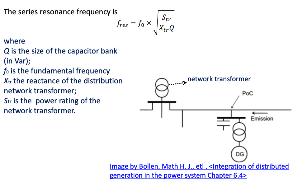
Case Study - Series Resonance
Case Study - Series Resonance Caused by Interaction between Shunt Capacitor Bank and Transformer - 1
- In a practical power distribution network, shunt capacitance can be installed for the following objectives:
– Capacitance bank can be installed beside an induction generator (directly connected to the grid) to provide reactive power support
– Distributed capacitors may be installed to filter out the switching harmonics produced by PE converters
– Capacitor bank might be installed in weak grid to enable large power deliveryOne draw-back of the shunt capacitor is that it may resonance with network series impedances.
Since the leakage reactance of distribution transformer are usually much larger than the power lines, the network impedance can be approximately by the leakage reactance of the distribution transformer.
Case Study - Series Resonance Risk Caused by Interaction between Shunt Capacitor Bank and Transformer - 2
Example – Series Resonance between Capacitor Bank and Transformer - 1
Consider a weak medium-voltage network, supplied by a 10 MVA, 10% transformer. A 2 MVA induction generator (magnetizing reactance 4.1 p.u.; leakage reactance 0.17 p.u. based on 2 MVA) is connected to this medium-voltage network through a 2 MVA, 6% generator transformer. A switched capacitor bank is installed at the medium-voltage feeder close to the point of connection to compensate for the reactive power consumption of the generator.
(i) Calculate the reactive power at no load
(ii) Calculate the reactive power at full load.
(iii) Calculate the range of capacitance connected to MV network and corresponding resonance frequencies.
(iv) For which harmonic order there is a risk of resonance? Calculate the size of capacitance for which the resonance will occur in the calculated harmonic.
Example – Series Resonance between Capacitor Bank and Transformer - 2
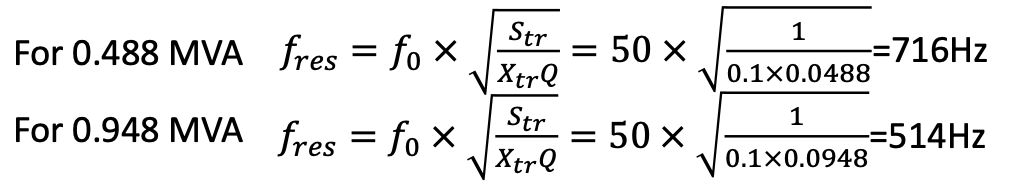
(i)Calculate the reactive power at no load
The reactive power at no load is 2/4.1 = 0.488 Mvar
(ii)Calculate the reactive power at full load.
The reactive power at full load is 0.488+(0.17+0.06)X2 = 0.948 Mvar
(iii)Calculate the desirable range of capacitance connected to MV network and corresponding resonance frequencies.
To compensate the full reactive power, the size of the reactive power compensation is between 0.488 and 0.948 Mvar.
Example – Series Resonance between Capacitor Bank and Transformer - 3
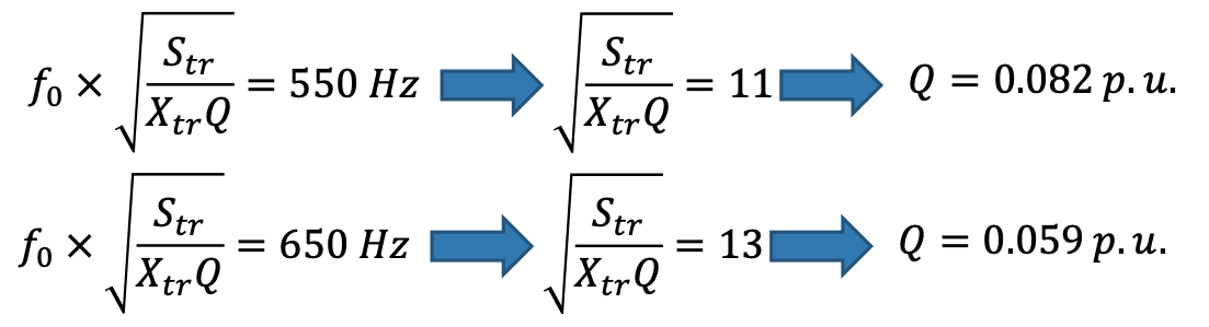
(iv)For which harmonic order there is a risk of resonance? Calculate the size of capacitance for which the resonance will occur in the calculated harmonic.
11th and 13th harmonics (at 550 Hz and 650) is between 514 Hz and 716 Hz.
- In a practical power distribution network, shunt capacitance can be installed for the following objectives:
-
-