-
Bollen, Math H. J., etl . Integration of distributed generation in the power system , Chapter 4
Jenkins, N , etl. Distributed generation, Chapter7
Chen D., Xu L. (2017) AC and DC Microgrid with Distributed Energy Resources. In: VeneriO. (eds) Technologies and Applications for Smart Charging of Electric and Plug-in Hybrid Vehicles. Springer, Cham
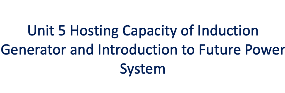
Unit Overview
In this unit, you will learn:
● How to determine the hosting capacity of an induction generator against voltage variation in a distribution network.
● The sharing of hosting capacity
● The concept of power system reliability
● Concepts of future distribution power system -
Introduction of Induction Machine based Renewable Generation
In the previous section, we have discussed how the active power generation may affect the voltage variation and the corresponding HCs. Practically, DGs may not only generate active power but absorb or inject reactive power into a distribution network as well. DG reactive power may also result in voltage variation.
Induction generator, which was one of the most mature type of wind turbine generator, is a typical example that has to consume reactive power during normal operation.
- The development in wind turbine systems has been steady in the past 50 years and it has witness a few generations of technologies.
- The wind turbine technology can basically be divided into three categories:
● the systems without power electronics: e.g. Induction Generator (IG directly connected to AC grid)
● the systems with partially rated power electronics (Double Fed IG)
● the systems with full-scale power electronic interfacing wind turbines: e.g. Permanent Magnet Synchronous Generator, Induction Generator (IG fully interfaced by power converter)
Introduction to IG based Wind Turbine
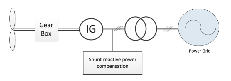
As is shown above, an induction generator based wind turbine system consists of turbine, gear box, IG, shunt compensation and interface transformer.
● An IG keeps an almost fixed speed (variation of 1–2%).
● A reactive power compensator:by switching on/off the capacitor banks and following load variation (5–25 steps).
● An IG system may cause fast voltage fluctuation due to the switching.
● An IG is featured for low cost and high reliability.
The reactive Power Concern of Induction Generator
(quick recap on how induction machine work )
As is the characteristics of induction machines, an induction generator has the following features:
- An IG normally has limited operation region of speed if the terminal voltage is fixed.
- An IG requires significant reactive power to build up the field.
- As an early generation of wind power generation technology (without PE): popular 20 years ago and has gain some more attention again for those lostcost DG solutions.
- The reactive power required for an IG concerns 2 components:
– Magnetizing current: Proportional to V2>br> – Reactive power loss due to the leakage reactance: Proportional to I2- For a power network with mainly inductive power lines, reactive consumption will lead to a voltage drop towards the reactive power consumptions.
Reactive power consumption for IG
In order to reduce the losses caused by reactive power, the components of the reactive power consumed by an IG has to be studied:
- The 1st component is proportional to the magnetizing current, which is almost fixed.
– The magnetizing reactance is considered to be unchanged at steady state
– This means it can be compensated with a fix reactive power compensation: e.g. a shunt capacitor bank.- The second term is proportional to the active power, when the max power to generate is 𝑃𝑚𝑎𝑥, the corresponding leakage reactive power consumption will be: 𝑄𝑚𝑎𝑥 = 𝛼 ×𝑃𝑚𝑎𝑥 where is 𝛼 a factor determined by induction impedances and slip corresponding to the maximum power.
Thus, the voltage rise of a feeder at maximum production is:
∆𝑈𝑔𝑒𝑛,𝑚𝑎𝑥= 𝑅𝑃𝑚𝑎𝑥 −𝑋𝑄𝑚𝑎𝑥 where X an R are the feeder impedance
Therefore: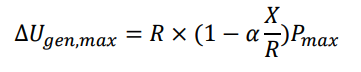
Host Capacity for Induction Generator - 1
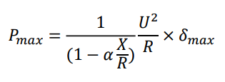
- From the general constraint of voltage margin, the host capacity of DG with predefined relative voltage margin δmax at unit power is
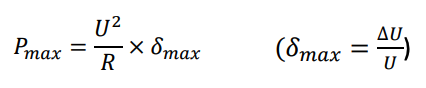
- Considering the new voltage rise with reactive power is
- The Hosting Capacity for an induction generator against voltage variation (with reactive power consumption) is
Host Capacity for Induction Generator - 2
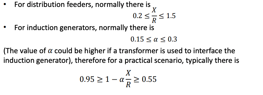
From the above expression, it can been that the X/R ratio of the feeder and the 𝛼 factor will affect of the HC of an IG.
Host Capacity for Induction Generator - 3
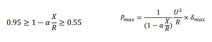
- From the above, it can inferred that he HC of an induction generator can be higher than the unit power factor condition as the reactive consumption can neutralize the voltage rise cause by active power injection. The HC can be increased with
– larger X/R ratio (longer distribution line)
– Larger 𝛼 : larger leakage reactance values of induction machine and transformer- For large 𝛼 values, the hosting capacity may become twice the value for generators without any reactive power compensation.
Host Capacity for Induction Generator - 4
- For a small-scale IG connecting to an infinite bus via a distribution feeder,
Considering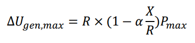
To make the voltage unchanged, there is
∆𝑈𝑔𝑒𝑛,𝑚𝑎𝑥 = 0
hence
Therefore, when the IG can match the feeder characteristics and let the following condition happens:
𝜶 = 𝑹 /X The steady state voltage variation of the IG terminal against the infinite bus is 0.
Host Capacity with Reactive Compensation
- Most power electronics based DGs can regulate reactive power as well as outputting active power.
- Theoretically if a lagging power factor can be chosen for a PE based DG, the voltage rise can be regulated at zero for any amount of power produced.
- Drawbacks:
– When the X/R ratio is small, the effectiveness is limited, typically for low voltage system.
– Extra reactive power also means extra losses on the DG side.
– Improper control may give rise to reactive power circulation when there are multiple DGs in the network.
– Extra current rating is required for the DG.
– Practically very difficult to keep the voltage rise zero at every DG terminals -
Sharing of Hosting Capacity Against Voltage Variation
The Sharing of Hosting Capacity - 1
- It is common that more than one DG is connected at a certain location.
- To make sure the performance index are met, DGs at the same location have to share the HC properly
- The maximum production should not exceed the hosting capacity at that location
- The hosting capacity should be distributed roughly inversely proportional to the generator location:
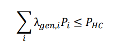
where 𝑃𝐻𝐶 is the hosting capacity at the end of the feeder; 𝜆𝑔𝑒𝑛,𝑖 is the ratio of the distance from the start of the feeder to 𝑖th DG against the length of the entire feeder; 𝑃𝑖 is the HC for the ith DG.
Hosting Capacity Sharing - 2
- For N generators connecting to the same feeder bus:
– Considering each DG is outputting full power at the same time for the most severe case
– the allocation of each generator is: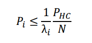
This equation means that the closer one DG is located to the main bus (𝜆=0) the larger HC it can be allocated.
Example – Hosting Capacity Sharing
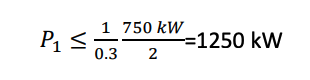
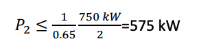
Assume a feeder is with a minimum hosting capacity (against voltage variation) of 750 kW. Two DGs are planned to be connected to the upstream feeder bus. One is going to be connected at a position of 30% of the feeder length from the feeder bus and the other 65% from the feeder bus. Find out the maximum ratings for both DGs.
For the DG rating at the position of 30% length from the bus
For the DG rating at the position of 65% length from the bus
-
DG and Power System Reliability
- Reliability is an inherent characteristics to describe the ability of a system to perform its intended function.
- In power system the primary function is to supply electrical energy to the end users(consumers).
- Reliability is usually express in percentage. E.g. 100 % reliability means the power supply can be provided to end users at all time; whereas 0% means the power supply can never be provided.
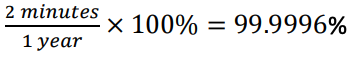
- Power supply reliability can be measured by
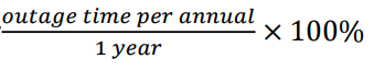
– In a highly reliable power distribution system, if the annual outage time is 2 min; the reliability can be as much as
– In some developed rural area, the reliability can be 60% or lower, with an outage a few hours per day.
Cost - Reliability
Reliability has one of the most important index for distribution power system managers, designers, planners and operators to ensure :
– Consumers are receiving adequate and secure supplies
– The power system is operating within reasonable economic constraints.
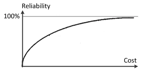
- It is expected that higher reliability means higher cost of investment.
- And in a power system, the close the reliability to 100%, the incremental cost for the per unit reliability will also be higher as well, which is illustrated above
- E.g. The investment cost to improve the reliability of a distribution network from 60% to 70% will be generally lower than from 89%-99%
- Therefore, although renewable DG and some conceptual future power network technology are capable to improve the reliability up to a very high standard, the consideration of the investment cost will always be a constraint
DG and Power Distribution Reliability
- Load shedding is one of the main reasons that lower the reliability of a distribution power system
– It can be caused by insufficient energy source for the load demand.
– Example: cooling demand cannot be met in tropical rural area.
– Load shedding will be carried out when feeders are overloading.
– DG of renewable (PV for instance) can be used to reduce the area/time of shedding area.- Network fault or planned maintenance can cause outage of the entire downstream in a conventional network
– A planned islanding operation with DG can power an area during a permanent fault or a planned maintenance disconnection at the upstream; hence reliability can be improved -
DG and Future Distribution Power System
DG and Future Power System
- Distributed generation will continue to increase as many countries seeking to de-carbonize their energy systems.
- With the aid of communications and power electronics technology, the integration of significant renewable DG is changing the distribution networks from passive to active and new technologies are emerging.
- This is one of the main drive towards smart grid.
- The improvement of system performance has to be considered as well as investment cost.
Bollen, Math H. J., etl . ntegration of distributed generation in the power system , Chapter 7
Concepts of Future Distribution Power System
Although it is agreed that distributed generation must be integrated more effectively into the power system, which is one the drive towards smart grid, there remains considerable ambiguity as to what this means in practice. A few illustrative concepts are as follows:
- Active network management>br> – which allows more distributed generation to be connected to distribution networks and operated effectively
- Virtual power plants
– which provides a means of aggregating a large number of small generators and facilitating access to markets- Microgrids
– which allow the formation of small cells of microgeneration and controllable loads (and storages) as one distributed entity- The use of power electronics technology
– which upgrades the system performance with great flexibility and potential
Please read: Jenkins, N , etl. Distributed generation Chapter 7
Active Network Management
- Instead of allowing DGs connected to a distribution network passively, the distribution network can also mange the DG resources actively to maximize the HCs.
- A more serious difficulty comes with the dramatically increased complexity when a number of individual active network management schemes are installed in the same section of network.
- Then a system-wide solution becomes necessary to coordinate multiple active management schemes.
- The elements within the distribution network can actively coordinate with each other; hence the term of “active network management”.
- So far, there is no agreed standard on such coordination
Illustration: Generator Reduction and Special Protection Schemes -1
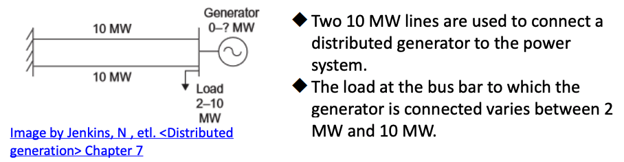
- For “fit-and-forget” scheme, the generator should be allowed to export its full output at any time.
- For the worst case, one circuit can be out of service at any time, the maximum rating of generation that could be connected is (10+2) MW.
- If the generator is an intermittent renewable source, it will only operate at its rated output for very limited time, e.g 30% of all time.
- The chance of maximum generation coincide with minimum load is limited.
To upgrade to an “active management” system
- A DG greater than 10 MW up to 20 MW can be installed with dynamic monitoring over the load and line conditions, which is more cost-effective.
- The DG output can be actively reduced if the line rating and load constraint is reached.
- For a more desirable scenario, if the intermittent source is very unlikely to stay at max rating for a prolong period of time (PV for instance), the rating can be further upgraded to 30 MW.
Drawbacks of such upgrade:
- Protection, stability may be a risk as the closed-loop control may introduce unexpected oscillations
- The DG is not a fit-and-forget anymore. real time monitoring, communication and control add up to the complexity which can lead to the risks of reliability and increase the investment cost.
Active Management-Dynamic line ratings
- For a wind power generation, both output power and the capacity of the connected power lines are affected the environmental conditions.
– High wind speed usually means high power output.
– High wind speed also means better cooling condition for power lines; therefore extra power capacity for overhead lines.
– Low ambient temperature can contribute to extra power transmission capacity as well.- By monitoring the environmental conditions of the overhead lines, the actual capacity of the power line can be assessed dynamically and allow more extraction of renewable energy when the condition permit.
Watch how an industry implement dynamic line rating.
Active Management-Active network voltage control
- The tap changers of the distribution transformer (typically at 33 kV/ 11 kV) can be used to control the voltage.
• In normal operation, measurements are taken and feed into Distribution Management System Controller (DMSC) in real time.
• DMSC gather the information detected and determines the optimum operating points of both the tap changers and the generator outputs in real time and kept updating them.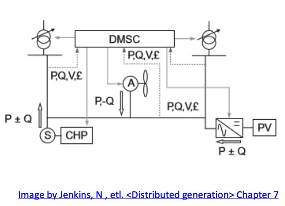
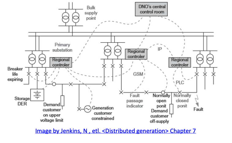
Active Management-Integrated Wide-Area Active Network Management
- The introduction of smart meter gives better visibility of a distribution network and historical data.
- The operational state can be estimated based on historical data modelling and real-time data
Active Management – One illustrative Concept of DMSC
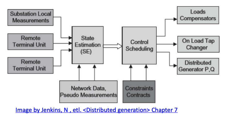
- Historical load data are fed into an under-determined distribution state estimator to give a representation of the voltage and power flows within the network.
- These voltages and power flows are then used by a controller, to determine the best control action to be taken.
Drawbacks:
- The effectiveness of the optimization heavily rely on the accuracy of the estimation.
- Takes a long time to gather effective historical data hence conservative to system change/evolvement .
Active Management - Virtual Power Plants 1
One of the major challenge of renewable DGs is the number of the plants.
- Small distributed generators are not visible to system operators as the real-time monitoring of a large number of small DG sources is neither practical nor economical to a transmission system operator.
- Unchanged operation style of conventional power plants will lead to very large generation plant margins, under-utilization of assets and low operating efficiencies.
- By using a control agent to look after a number of DGs, it allows large number of small DGs to be aggregated gives the concept of virtual power plant
- As the aggregation of small DGs are more visible, they can take part in the various markets for energy and ancillary services; such as automatic generation control and whole sale
How might a VPP look like ?
Active Management - Virtual Power Plants 2
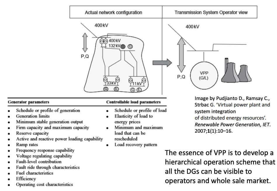
- VPP also creates a single operating profile from a composite of the parameters characterizing each small generator.
- The VPP is characterized by the set of parameters usually associated with a traditional transmission-connected generator: scheduled output, ramp rates, voltage regulation capability, reserve, etc.
- A virtual power plant performs in a manner similar to a transmission connected large generating unit.
Active Management - Virtual Power Plants 3
Active Management - Microgrid
- It is very difficult for the power system to balance countless, growing and intermittent renewable DGs against the loads in a traditional way.
- A decentralized but systematic view has to be taken.
- The best way to accommodate intermittent DG is to consume them as much as possible locally.
- By integrating all the DGs, load and storage ogether, a micro power system is formed, hence the nomination of microgrid.
- So far, there is no general agreement on what the best microgrid architecture or the control techniques that should be used.
- To date, microgrids have not been implemented widely in public electricity supply systems, and a robust commercial justification or business case for their use has yet to be developed.
What a microgrid might look like?
Microgrid Structure
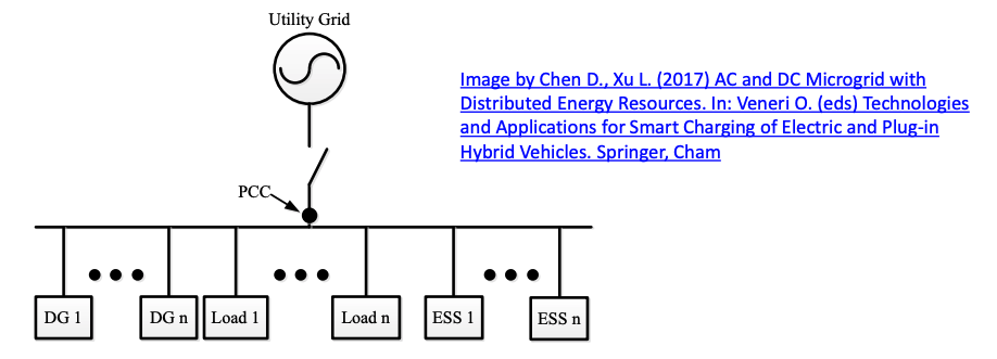
- A typical microgrid structure is shown as above: the entire downstream side of the PCC point is area of the microgrid
- Comparing with traditional power grid, the emergence of DGs and Energy Storage Systems (ESSs) is the major difference.
- In a microgrid, renewable DGs and ESSs are interfaced with power electronics converters with distributed controller
- The ESS should be able to back an planned islanding operation during an outage along with DGs
- The size is normally small: up to a few MWs
Microgrid Concept
The objectives of Microgrid:
- To be a good “citizen” to the external utility grid
– Provide controllable/scheduled power flow
– Provide auxiliary support to utilities:
– Provide frequency support, reactive power support
– Comply with grid requirement: fault-ride-through, etc.- To be perfect power supplier to the internal end-user – Provide uninterrupted power supply even during a utility fault – Able to sustain a prolonged islanding operation automatically during an outage or when the utility grid is out of reach
Challenges of microgrids:
- Both the control the power flow and islanding operation will need energy storage system, which is costly
- To achieve perfect power supply requires challenging power electronic control technique.
The Control of Microgrid - 1 (AC)
- Principles:
– When a micrgrid is connected to a utility grid, the microgrid’s voltage simply follow the main grid
– When a microgrid is not connected to utility grid, the external voltage is lost.
– A microgrid should be able to establish a local power grid when it is islanding.
– To establish a power grid, a steady voltage has to be formed by certain sources which is independent of the power exchange. This means that the source should be therefore be able to adjust their power exchange to maintain the power balance.
– E.g. for the utility grid, the voltage is backed by those synchronous generators of the power plants.
• During grid connected mode, the voltage provider is utility grid
• During islanding mode, the voltage of an microgrid is sustanied by loca Energy Storage System (ESS).
The Control of Microgrid - 2 (AC)
- During grid-connected mode
– The microgrid voltage is provided by the utility grid
– The exchange power is controllable with energy storage, load shedding or generation curtailment. The latter two are less favorable but as an emergency choice.
– Auxiliary support can be provided as an optional service: reactive power support and control damping can be provided by the internal PE resources (energy storage converter)- During islanding mode
– The utility grid is disconnected so a replacement of the voltage source is essential.
– The net power within an island can be any value within rating (either surplus or deficit).
– The net power can change very fast.
– The new voltage source has to be able to balance this net power very fast (in milli-seconds) so as not to collapse
– Energy storage system (battery with PE converter) will become the voltage source provider utilizing a bidirectional power converter.
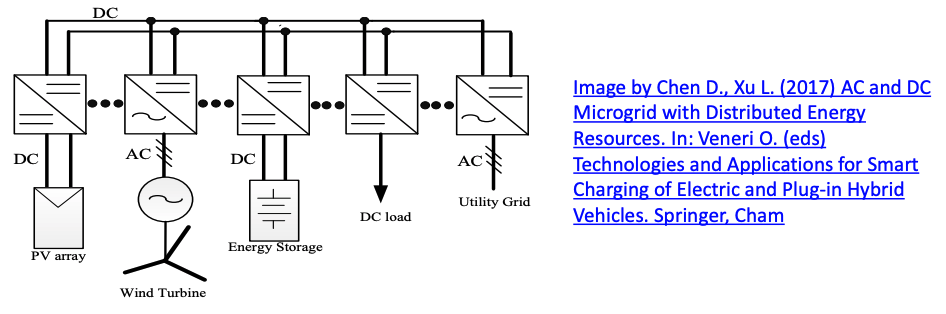
The Introduction of DC Microgrid
By utilizing DC buses, DC microgrid is proposed to connect intermittent renewable power sources, energy storages and DC loads, which is illustrated below.
- This is due to the fact that many renewable power sources, e.g. directlydriven wind turbine, photovoltaic system, and energy storage systems, e.g., battery, super capacitor, normally have DC links at their interface converter stages.
- By interconnecting the DC links with common voltage level of all the distributed resources, a DC microgrid is formed.
- The difference between DC microgrid and an AC one is that the interface to the utility grid has to be a bidirectional DC/AC converter.
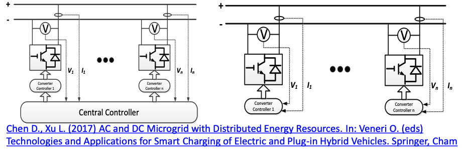
Control of DC Microgrid
Principles:
- Similar to AC grid, a voltage source needs to be created to backbone a grid
- Unlike AC grid, the voltage source is always created by an PE converter, regardless the utility grid is available or not.
- A DC system boasts its relatively easy control of voltage as there is no concern of frequency or reactive power
- Within a DC system is easier to implement plug-and-play and decentralized control schemes.
Challenge:
- No established protection scheme for a bi-directional LVDC network
- Safety issue regarding DC arcing is always a concern