-

Dr Azmy Gowaid
School of Computing, Engineering and Built Environment
Glasgow Caledonian University
Email: azmy.gowaid@gcal.ac.uk -
Grid Connection of Renewable Power Plants
Renewables Grid-Connection Challenges
- Due to the nature of renewable energy resources and the technology used for grid interface, several challenges arise upon grid connection
- These challenges are caused either by the stochastic nature of the renewable energy resource, or by the grid interface systems, or sometimes a mix of both.
- Many types of renewable power plants are connected to the grid using DC/AC power converters whether full-rating (as in solar PV, PMSG-WT, any HVDC line) or partialrating (as in DFIG-WTs).
- For example, any power plant that is connected to the grid through a DC/AC power converter is endangered under AC and DC faults.
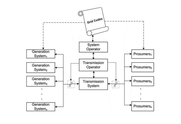
- DSOs (distribution system operators) and TSOs (transmission system operators) have reacted to these challenges by setting specific regulations that renewable power plant owners must adhere to in order to get connected.
- Grid Codes (GCs) are instructions that describe the technical and operational characteristic requirements of the connected power plants.
Regulations on Renewables Grid Connection
- GCs usually apply to conventional power plants as well as large renewable power parks/plants (RPP). However, some can be specific to RPPs.
- Grid Codes are instructions that address, among other issue, the technical and operational characteristic requirements of the power plants.
Classification of Grid Codes
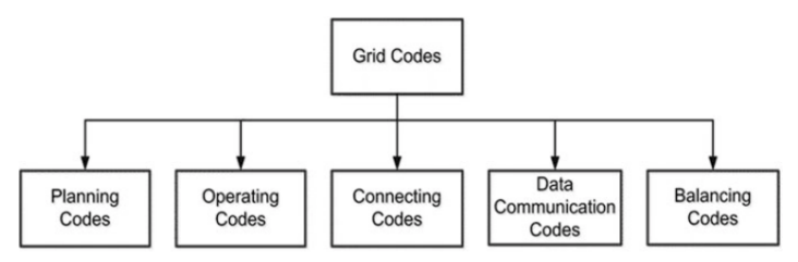
- planning codes (PC): deal with dimensioning, planning, and development of the power plant and other equipment.
- The connecting code (CC): discusses the connection requirements and conditions to remain connected to the grid
- operating codes (OC): discusses the operational requirements of various equipment in the power system.
- Data communication codes (DCC): deals with the requirement for data communication and storage, amount of data storage and quantities to be stored
- Balance Code (BC): specifies the requirements to maintain the terminalvoltage and frequency, under normal and emergency conditions.
Regulations on Renewables Grid Connection
- The new GCs stipulate that RPPs should contribute to power system control (frequency and voltage) much as the conventional power stations.
- GC requirements are grid specific. Each TSO formulates its GC requirements depending on many factors which differ from a grid to another, such as: grid size, grid strength, interconnections, RPP penetration level, generation mix, total inertia.
- the GC of E.ON Netz (a German TSO) published in April 2006 was the first to elaborate such requirements for RPPs
- E.ON Netz requirements are often used as a reference for other codes.
The main RPP integration concerns for TSOs include:
- Low-Voltage/Fault Ride-through (LVRT/FRT) capability;
- Active power and frequency control;
- System voltage and frequency limits;
- Reactive power/power factor and voltage control capabilities.
- Voltage Flicker and harmonic injection into network (voltage quality)
-
Grid Code Requirements (Connecting Code)
Tolerance to Steady-State Voltage Variations
Normal operating voltage ranges of the UK national electricity transmission system
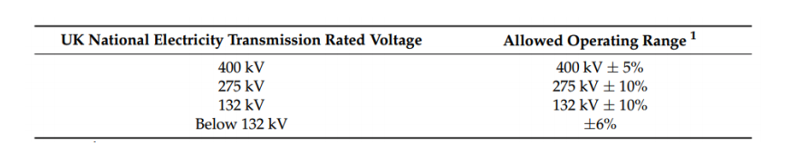
Any connected RPP must be able to handle these voltage variations without disconnecting or reducing power output.
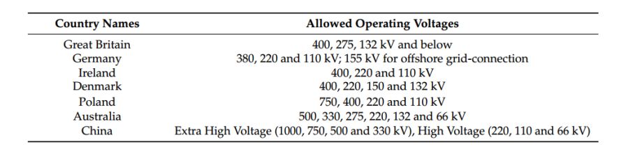
This tolerance is required as well in other grid codes. Transmission levels in other countries that RPP can connect to:
- Imbalances between demand and supply lead to frequency deviations from the nominal frequency (50Hz or 60Hz)
- Large frequency deviations can not only disrupt these generating units but also endusers’ machines.
- To prevent such an incident from occurring, power plant generators are normally equipped with frequency protection relays. The system operator sets the frequency limitation boundaries, so the relays can be triggered when the generators have to be disconnected from the grid to ensure the equipment safety.
- However, sometimes, the relays’ actuation can lead to cascading blackouts, that is, the generators disconnected from the grid in one area could draw in another area in losing its synchronism as well.
- If the frequency deviation cannot be corrected within a required time window, it may trigger a wide area power outage.
- During normal operation, the frequency is allowed to vary within a strict interval which has been defined by every national TSO.
- For a RPP connecting to the grid, this range of frequency variation must be regarded as steady-state and the RPP must operate at a continuous base with a constant active power output
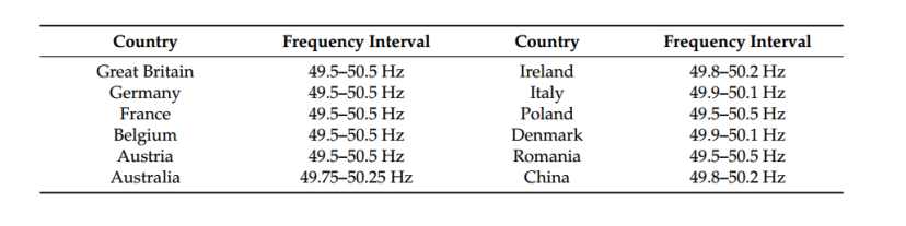
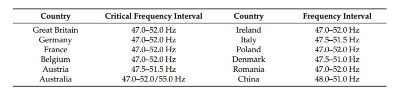
- RPP are required to continue operation, albeit with variation of active power output when the grid frequency spans a wider interval; normally known ‘critical frequency interval’
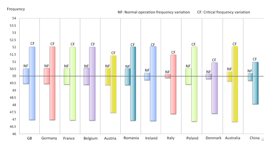
Graphical visualization of the normal and critical frequency intervals in different countries
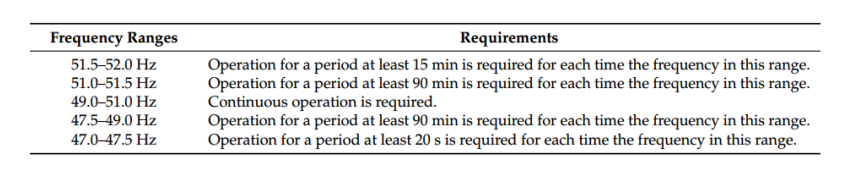
In the UK, when grid-connected RPP operate under the wider critical frequency interval, their active power output must be maintained at a certain level for a period of time dependent on the frequency value, after which RPP is allowed to trip frequency relays.
As long as the RPP is still connected under a frequency deviation it must provide a level of frequency response to the grid to rebalance the frequency. In addition to inertial response, Frequency responses in general can be:
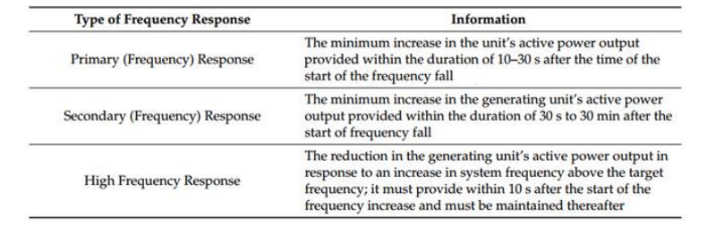
Frequency Response Requirement in the UK
Upon a frequency drop below 50Hz, a conventional power plant or RPP must respond:
0-10s: Increase its output by inertia response or emulate inertia response.
10-30s: An extra value P of primary control power must be pushed into the grid.
30s-30min: secondary control power of value S must be produced.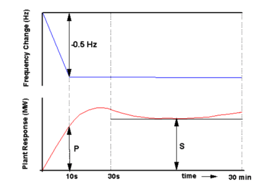
Frequency Response Requirement in the UK
Upon a frequency rise above 50Hz, a conventional power plant or RPP must respond:
0-10s: reduce output by inertial response or emulate inertia response.
At 10s: curtail power output by a high-frequency response value H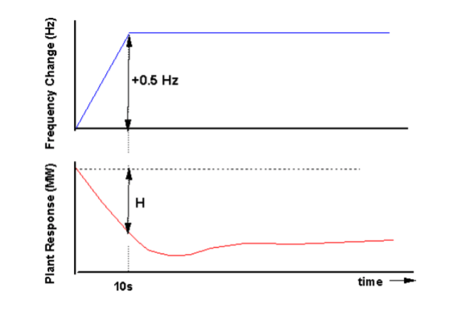
The minimum frequency response required for a ±0.5 Hz frequency deviation is shown.
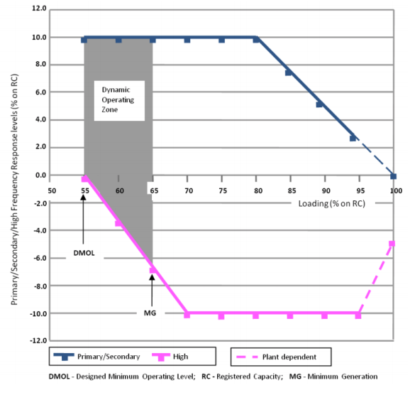
The values of P, S, and H are set depending on the amount of power output at the time of contingency in percent of the plant registered capacity (RC)
The value of P and S decreases when the RPP produces higher power pre-contingency (as seen by the upper blue curve.
For an example, at generation of 90% of registered capacity, the generator should supply primary response (P = 5%) if the frequency drops by 0.5 Hz
The value of H decreases when the RPP produces less power pre-contingency as seen from the lower pink graph.
The term “designed minimum operating level” (DMOL) is defined as the output below which a generating unit has no high-frequency response capability
Low-Voltage/Fault Ride-Through Requirement
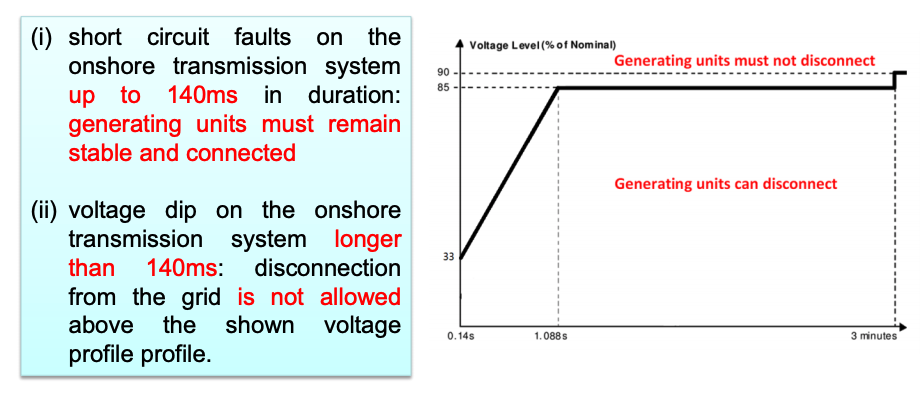
- GCs specify that generating units, including RPP, need to withstand voltage dips down to a certain percentage of the rated voltage (even 0% in some cases) with a specified duration, which is entitled Fault Ride-Through (FRT) or Low Voltage Ride-Through (LVRT) capability.
- The requirements for FRT/LVRT applied in the UK Supergrid (above 200 kV):
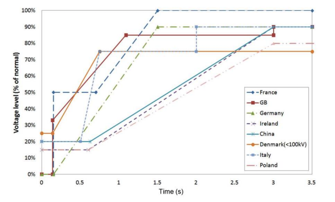
- This figure shows the FRT/LVRT requirement profiles in the UK, Germany, France, Italy, Ireland, Denmark, and China.
- The FRT/LVRT requirements depend on the specific characteristics of each power system and the protection employed.
- The requirements in the UK, Germany and France Grid Codes stipulate that the generating units in these countries must remain connection during voltage dips down to 0% in a certain period (140ms, 150ms and 150ms, respectively)
Reactive Power and Voltage Control Capabilities
- All grid codes demand from RPPs to provide reactive output regulation, often in response to power system voltage variations, much as the conventional power plants.
- The reactive power control requirements are related to the characteristics of each network; since the influence of the reactive power injection to the voltage level is dependent on the network short-circuit capacity and impedance.
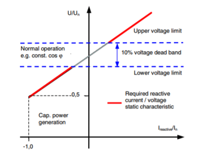
- Example: In the German E.ON Netz grid code, the voltage control must take place within 20 ms after fault detection by providing a reactive current on the low voltage side of the RPP connection transformer to at least 2% of the rated current for each percent of voltage dip or rise outside a 10% voltage dead band.
- The produced reactive power (current) must resemble over-excited operation during voltage dips, and under-excited operation in voltage swells.
- Over-excited operation produces reactive power to increase the voltage, while underexcited operation absorbs reactive power to bring the voltage down.
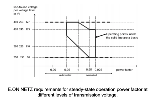
- E.ON NETZ Grid Code requires that generating plants (including RPPs) operate in steady-state within the power factor range indicated.
- The closed contour encloses all operating points corresponding to certain voltage levels. Operating range for nominal voltages 380 kV, 220 kV and 110 kV as well as for voltage swells up to (440 kV, 253 kV and 127 kV) and dips down to (350 kV, 193 kV and 96 kV) are correspondingly indicated.
CAN RPPs Comply with These Requirements???
-
Low-Voltage/Fault Ride Through Capability
Power Converters Under Fault
AC side Faults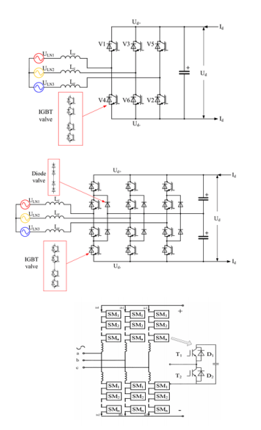
- The primary converter design used in connection of utility-scale RPPs (solar, wind, wave, etc.) is the 2-level three phase voltage source converter (VSC).
- At higher distribution and transmission voltage levels, VSC designs become more intricate
- Multilevel VSC and the Modular Multilevel Converter (MMC) are the most popular AC/DC power converter designs normally utilized for connecting large and offshore RPP to onshore grid through a high voltage DC (HVDC) line.
- When an AC voltage dip occurs at the point of connection to grid (point of common coupling PCC), the converter ability to export active power to the grid is reduced (P=VI)
- AC voltage dips occur due to various types of faults near the PCC.
- An AC voltage at the PCC can dip to zero if a bolted 3-phase AC fault occurs very near to or at the PCC. In this case, no active power can be exported to the AC grid from the RPP or the HVDC line.
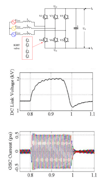
- At the DC side of the AC/DC converter, reduction or absence of active power export means all (or much of) the power produced by the RPP is trapped in the DC-link (DC circuit).
- This trapped power leads to a sharp rise (surge) in DC-link voltage that endangers break down of power electronic switches in the VSC if DC voltage exceeds their voltage rating.
- These graphs show the rise in DC-link voltage and GSC currents under a bolted three-phase AC fault at the PCC of a DFIG-WT (the controller increases GSC current in attempt to push more power into the grid).
- Insert Content Here 7