07
-
- Digital systems part 1

- ● Introduction
● Binary quantities and variables
● Logic gates
● Boolean algebra
● Combinational logic
● Boolean algebraic manipulation
● Algebraic simplification
● Karnaugh maps
● Automated methods of minimisation
● Propagation delay and hazards
● Number systems and binary arithmetic
● Numeric and alphabetic codes
● Examples of combinational logic design
-
- Introduction
- Watch the Video 📹
- ● Digital systems are concerned with digital signals
● Digital signals can take many forms
● Here we will concentrate on binary signals since these are the most common form of digital signals
– can be used individually
● perhaps to represent a single binary quantity or the state of a single switch
– can be used in combination
● to represent more complex quantities
-
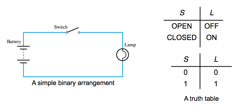
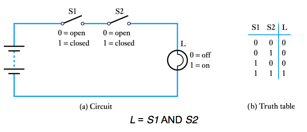
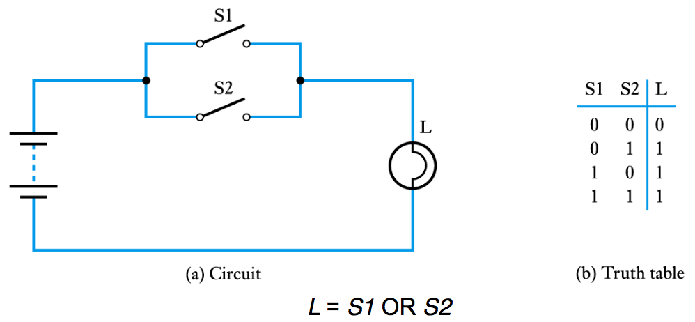
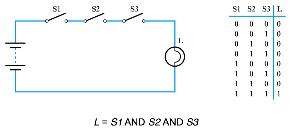
- Binary quantities and variables
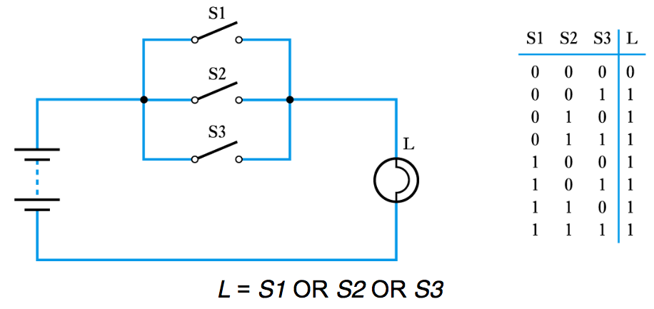
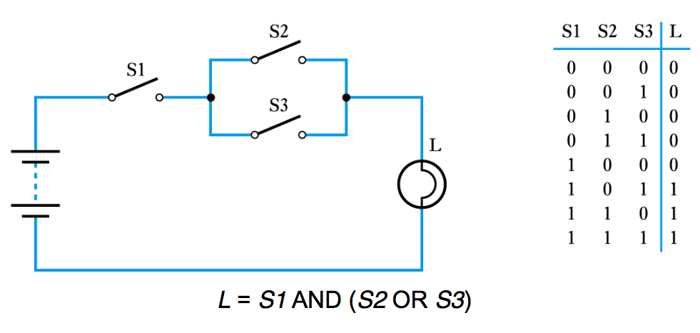
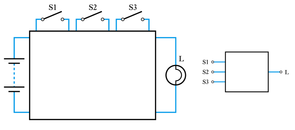
- ● A binary quantity is one that can take only 2 states
● A binary arrangement with two switches in series
● A binary arrangement with two switches in parallel
● Three switches in series
● Three switches in parallel
● A series/parallel arrangement
● Representing an unknown network
-
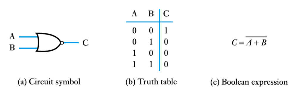
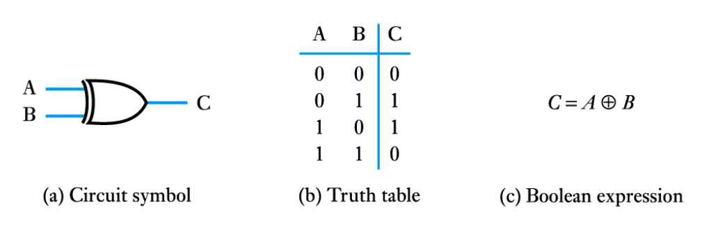
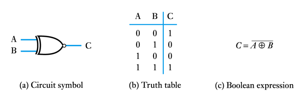
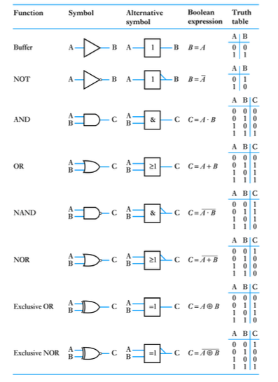
- Logic gates
- Watch the Video 📹
- ● The building blocks used to create digital circuits are logic gates
● There are three elementary logic gates and a range of other simple gates
● Each gate has its own logic symbol which allows complex functions to be represented by a logic diagram
● The function of each gate can be represented by a truth table or using Boolean notation
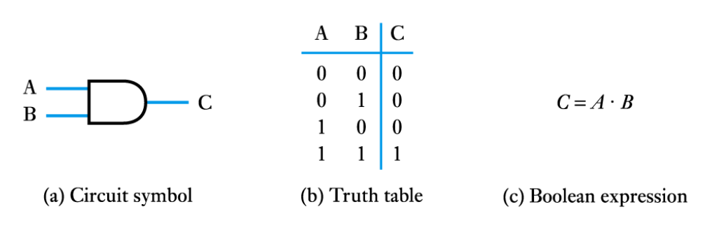
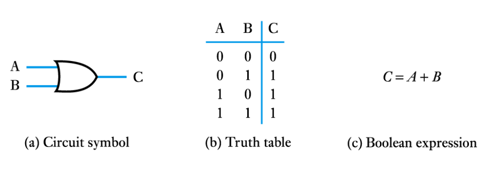
● The AND gate
● The OR gate
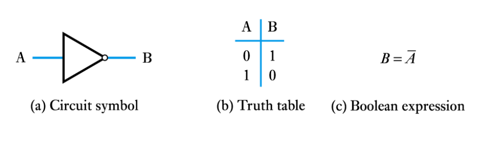
● The NOT gate (or inverter)
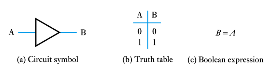
● A logic buffer gate
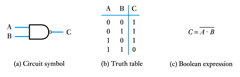
● The NAND gate
● The NOR gate
● The Exclusive OR gate
● The Exclusive NOR gate
● The symbols shown earlier for the various logic gates are the "distinctive shape‟ symbols
● Other symbols are also used such as those described in IEC 617 (shown under "Alternative symbol‟ here)
-
- Boolean algebra
- ● Boolean constants
– these are "0" (false) and "1" (true)
● Boolean variables
– variables that can only take the values "0" or "1"
● Boolean functions
– each of the logic functions (such as AND, OR and NOT) are represented by symbols as described above
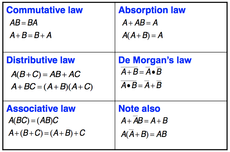
● Boolean theorems
– a set of identities and laws – see text for details
● Boolean identities
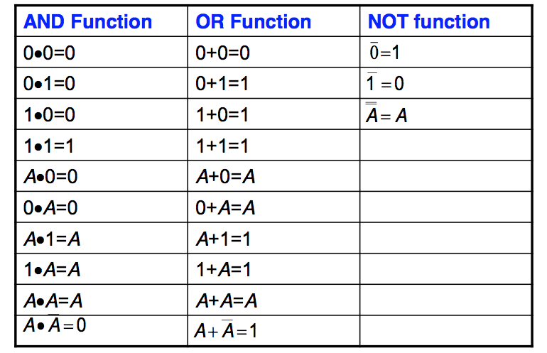
● Boolean laws
-
- Combinational logic
- Watch the Video 📹
- ● Digital systems may be divided into two broad categories:
– combinational logic
● where the outputs are determined solely by the current states of the inputs
– sequential logic
● where the outputs are determined not only by the current inputs but also by the sequence of inputs that led to the current state
● In this lecture we will look at combination logic
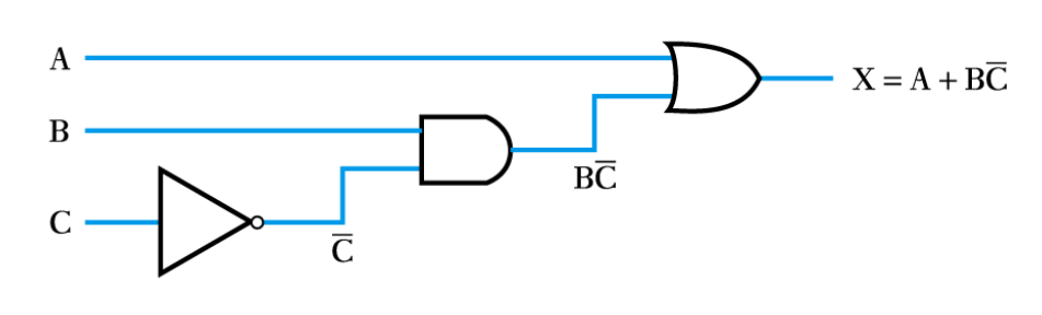
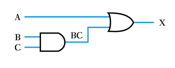
● Implementing a function from a Boolean expression
Example – see Example 24.1 in the course text
Implement the function X=A+B\overline{C}
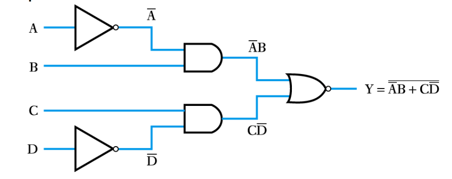
● Implementing a function from a Boolean expression
Example – see Example 24.2 in the course text
Implement the function Y=\overline{\overline{A}B+C\overline{D}}
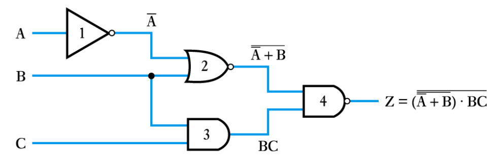
● Generating a Boolean expression from a logic diagram
Example – see Example 24.3 in the course text
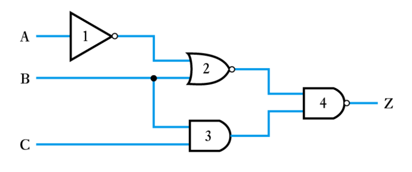
– work progressively from the inputs to the output adding logic expressions to the output of each gate in turn
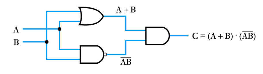
● Implementing a logic function from a description
Example – see Example 24.4 in the course text
The operation of the Exclusive OR gate can be stated as:
“The output should be true if either of its inputs are true, but not if both inputs are true”
This can be rephrased as:
“The output is true if A OR B is true,
AND if A AND B are NOT true.”
We can write this in Boolean notation as X=(A+B)\bullet(\overline{AB})
The logic function X=(A+B)\bullet(\overline{AB}) can then be implemented as before
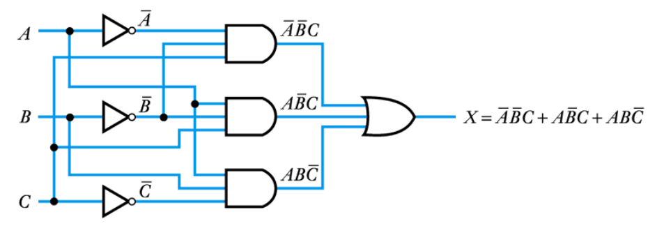
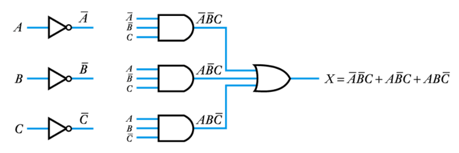
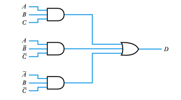
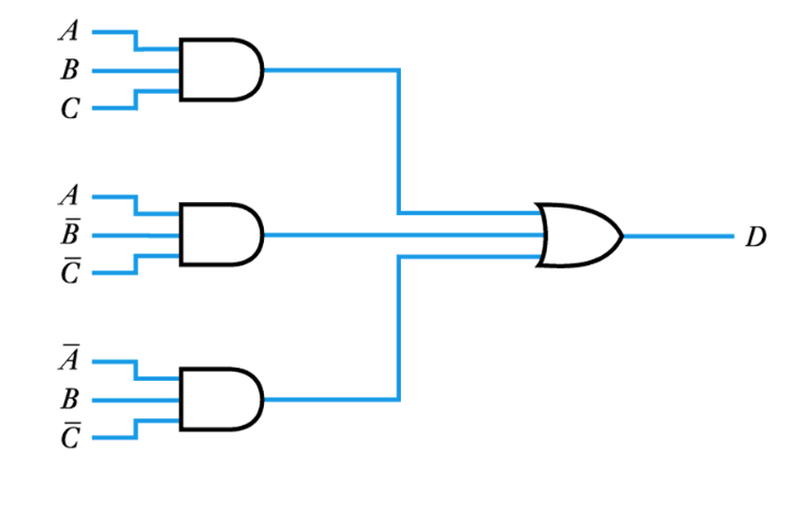
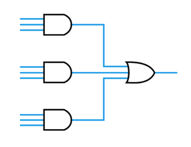
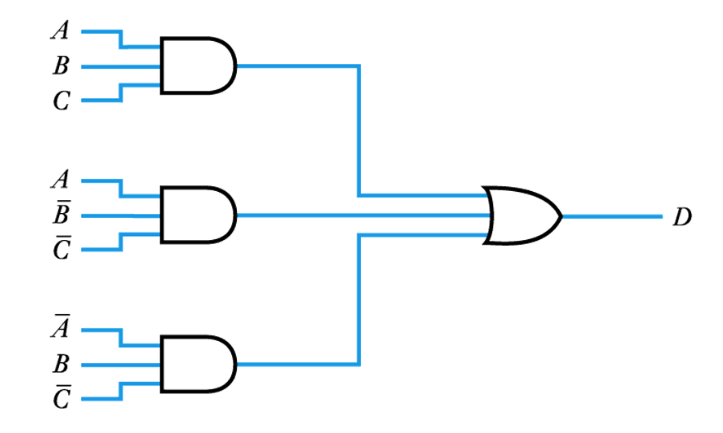
● Implementing a logic function from a truth table
Example – see Example 24.6 in the course text
Implement the function of the following truth table
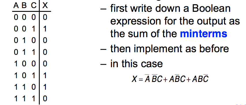
The logic function X=\overline{A}\ \overline{B}C+A\overline{B}C+AB\overline{C} can then be implemented as before
– Complex logic diagrams are often made easier to understand by the use of labels, rather than showing complex interconnections – the earlier circuit becomes
-
- Boolean algebraic manipulation
- ● We can use the various laws of Boolean algebra to change the form of circuits
– the following diagram shows the implications of the associative laws
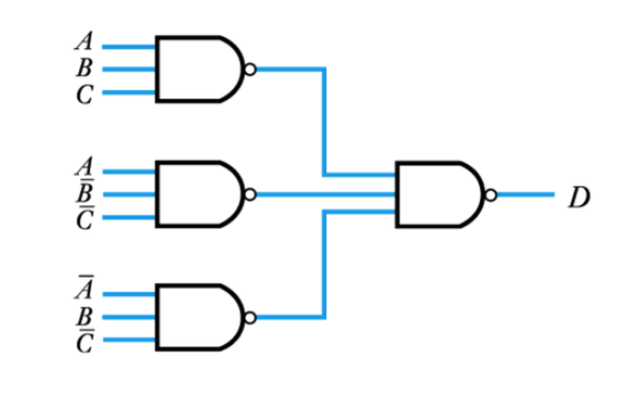
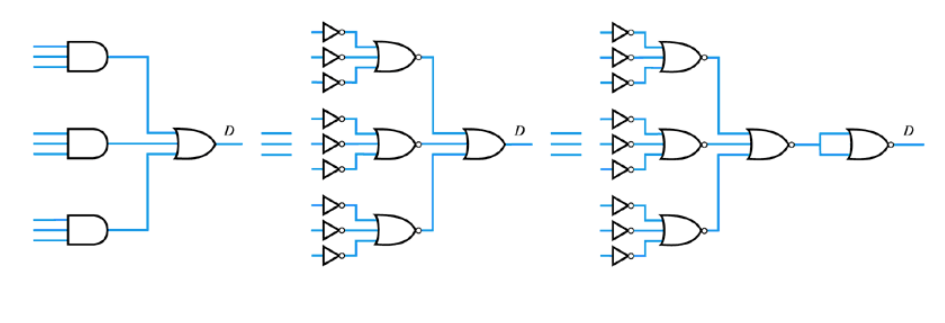
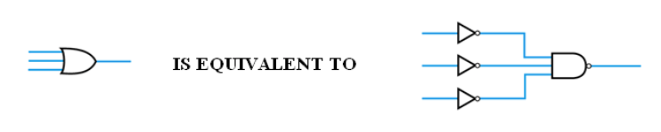
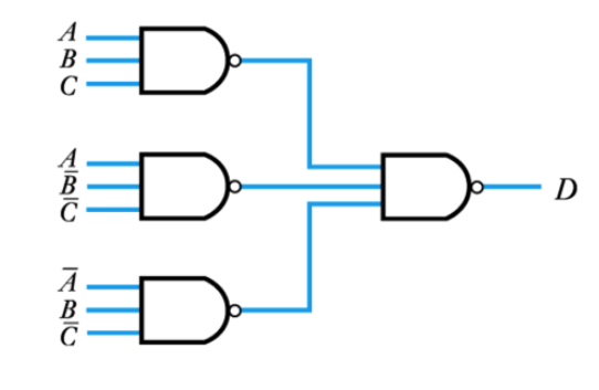
● Modifying circuits to use only NAND gates
– All combinational arrangements can be constructed as
– from De Morgan‟s theorem A+B+B=\overline {\overline A\,\overline B\, \overline C}
– therefore
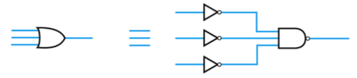
– therefore
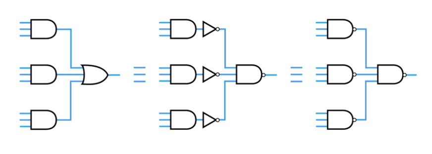
– hence any combinational arrangement can be constructed using only NAND gates
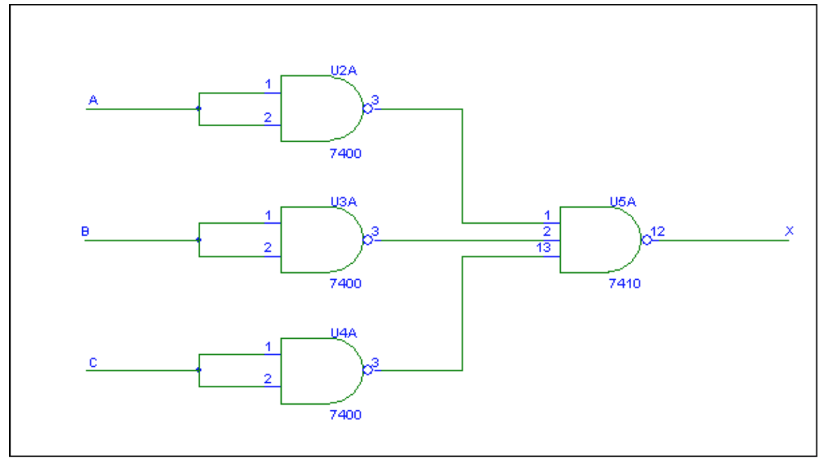
Example – see Example 24.7 in the course text.
Implement the following using only NAND gates
This becomes
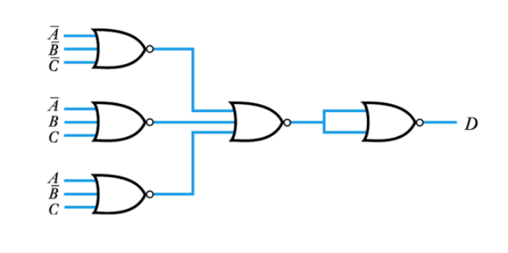
● Modifying circuits to use only NOR gates
– Similarly, from De Morgan‟s theorem
A\bullet B\bullet C=\overline{\overline{A}+\overline{B}+\overline{C}}
– therefore
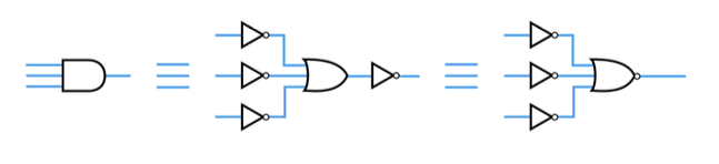
– therefore
– hence any combinational arrangement can be constructed using only NOR gates
● Example – see Example 24.8 in the course text
Implement the following using only NOR gates
This becomes
-
- Algebraic simplification
- Watch the Video 📹
- ● All combination circuits can be described in a sum-of-products form
– This consists of a number of terms (minterms or products) that are ORed together
– Examples include
A\overline{B}+\overline{A}B
XYZ+\overline{X}Y\overline{Z}+X\overline{Y}Z
AB\overline{C}D+\overline{AB}CD
– The sum-of-products must not include inversions of a series of term, as in
A\overline{BC}D+\overline{AB}CD
Example – see Example 24.9 in the course text
Implement the following expression:
X=ABC+\overline{A}BC+AC+A\overline{C}
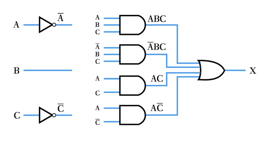
Example (continued)
Alternatively, the expression can be simplified
X=ABC+\overline{A}BC+AC+A\overline{C}
=BC(A+\overline{A})+A(C+C)
=BC+A
which can be implemented as
- De Morgan's Theorem
- Modifying circuits to use only NAND gates
– from De Morgan‟s theorem
A+B+C=\overline{\overline{A}\:\overline{B}\:\overline{C}}
– therefore
Example - From the logic expression draw a circuit using NAND gates only
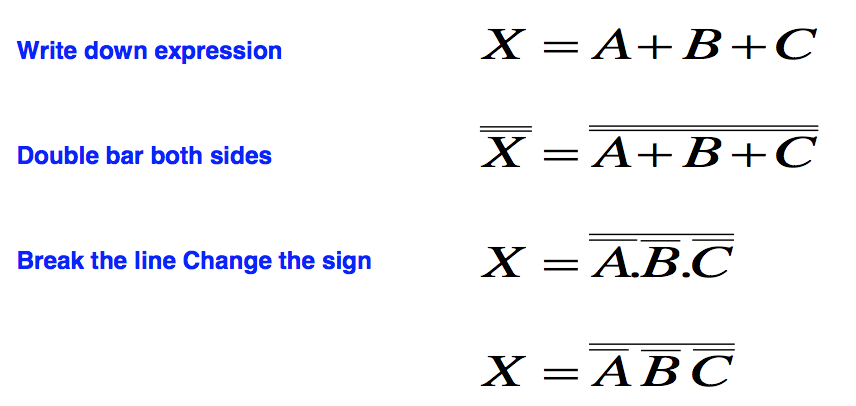
A+B+C=\overline{\overline{A}\:\overline{B}\:\overline{C}}
● Example – see Example 23.7 in the course text.
● Implement the following using only NAND gates
● This becomes
-