Wk 1
Basic Electric Circuits & Components
- Introduction
- SI Units and Common Prefixes
- Electrical Circuits
- Direct Currents and Alternating Currents
- Resistors, Capacitors and Inductors
- Ohm’s and Kirchhoff’s Laws
- Power Dissipation in Resistors
- Resistors in Series and Parallel
- Resistive Potential Dividers
- Sinusoidal Quantities
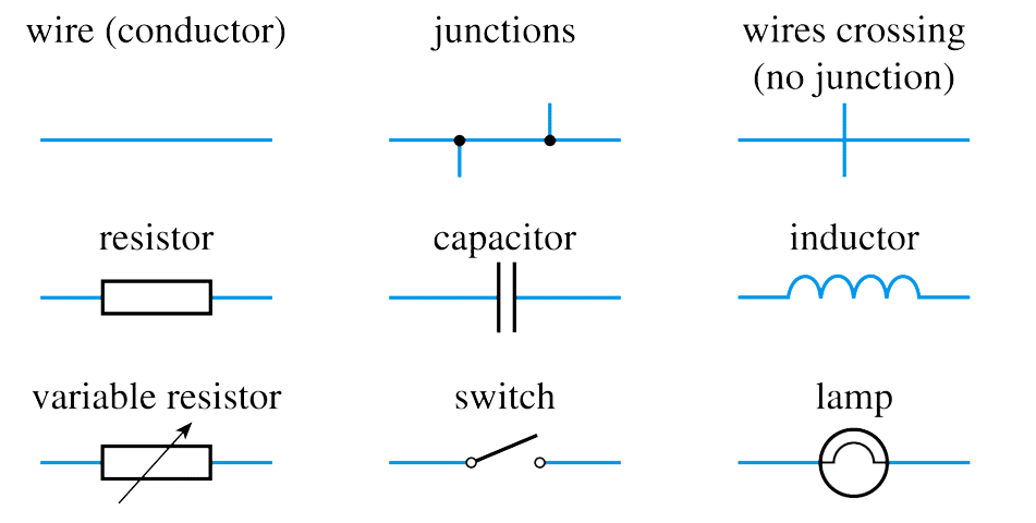
- Circuit Symbols
Introduction
- This lecture outlines the basics of Electrical Circuits
- For most students much of this will be familiar.
– this lecture can be seen as a revision session for this material- If there are any topics that you are unsure of (or that are new to you) you should get to grips with this material before the next lecture.
– the following lectures will assume a basic understanding of these topics- We will return to look at several of these topics in more detail in later lectures.
Common Prefixes
Prefix Name Meaning (multiply by) T tera 1012 G giga 109 M mega 106 k kilo 103 m milli 10-3 µ micro 10-6 n nano 10-9 p pico 10-12 SI Units
Quantity Quantity symbol Unit Unit symbol Capacitance C Farad F Charge Q Coulomb C Current I Ampere A Electromotive force E Volt V Frequency f Hertz Hz Inductance (self) L Henry H Period T Second s Potential difference V Volt V Power P Watt W Resistance R Ohm Ω Temperature T Kelvin K Time t Second s
Electrical Circuits
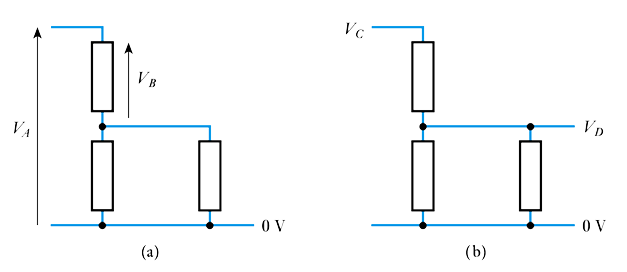
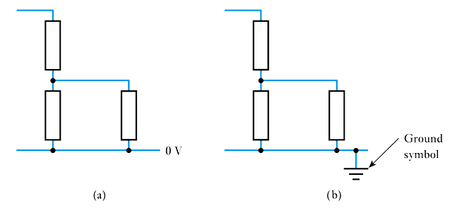
Voltage reference points
– all potentials within a circuit must be measured with respect to some other point.– 📷 We often measure voltages with respect to a zero volt reference called the ground or earth
Representing voltages in circuit diagrams
– conventions vary around the world.
– we normally use an arrow, which is taken to represent the voltage on the head with respect to the tail.
– labels represent voltages with respect to earth.
- Electric charge
– an amount of electrical energy.
– can be positive or negative.- Electric current
– a flow of electrical charge, often a flow of electrons.
– conventional current is in the opposite direction to a flow of electrons.- Current flow in a circuit
– a sustained current needs a complete circuit.
– also requires a stimulus to cause the charge to flow.- Electromotive force and potential difference
📷 A simple circuit– the stimulus that causes a current to flow is an e.m.f.
– this represents the energy introduced into the circuit by a battery or generator.
– this results in an electric potential at each point in the circuit.
– between any two points in the circuit there may exist a potential difference.
– both e.m.f. and potential difference are measured in volts.
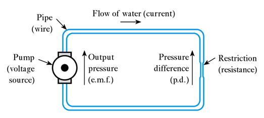
📷 A water based analogy of a circuit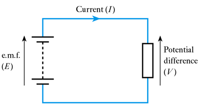
- Electric charge
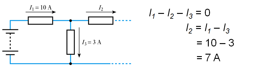
Kirchhoff’s Current Law
At any instant the algebraic sum of the currents flowing into any junction in a circuit is zero.📷 Kirchhoff’s Current Law example
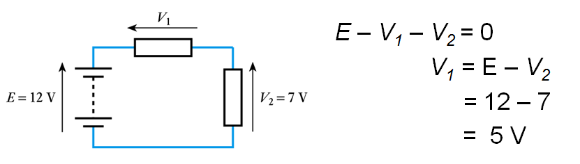
Kirchhoff’s Voltage Law
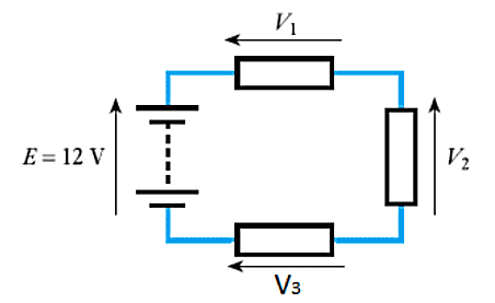
At any instant the algebraic sum of the voltages around any loop in a circuit is zero.📷 Kirchhoff’s Voltage Law example
\begin{align*} E - V_1 -V_2 &= 0 \\ V_1 &= \text{E} - V_2 \\ &= 12 - 7 \\ &= 5 \text{V} \end{align*}
- 🎥 Watch video on Kirchhoff's current and voltage laws - Adobe Flash video.
Power Dissipation in Resistors
The instantaneous power dissipation $P$ of a resistor is given by the product of the voltage across it and the current passing through it. Combining this result with Ohm’s law gives:\begin{align*} P =& VI \\ \\ P =& I^2 R \\ \\ P =& V^2 /R \end{align*}
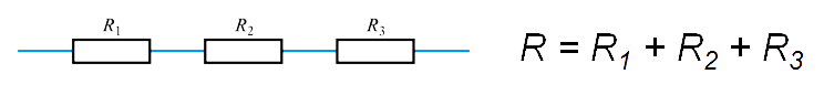
Resistors in Series and Parallel
📷 Resistors in Series Diagram
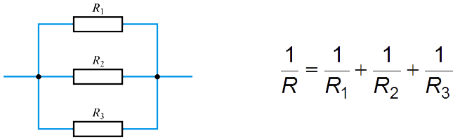
📷 Resistors in Parallel DiagramDirect Current and Alternating Current
Currents in electrical circuits may be constant or may vary with time.
When currents vary with time they may be unidirectional or alternating.
When the current flowing in a conductor always flows in the same direction this is direct current (DC).
When the direction of the current periodically changes this is alternating current (AC).
Resistors, Capacitors and Inductors
Resistors provide resistance
– they oppose the flow of electricity.
– measured in Ohms ($\Omega$).
Capacitors provide capacitance
– they store energy in an electric field.
– measured in Farads ($F$)
Inductors provide inductance.
– they store energy in a magnetic field.
– measured in Henry ($H$).
We will look at each component in later lectures
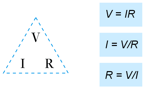
Ohm’s Law
The current flowing in a conductor is directly proportional to the applied voltage $V$ and inversely proportional to its resistance $R$.
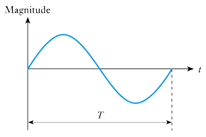
Sinusoidal Quantities
Length of time between corresponding points in successive cycles is the period $\text{T}$.Number of cycles per second is the frequency $f$:$f = 1/ \text{T}$
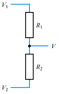
Resistive Potential Dividers
General case:
Example:
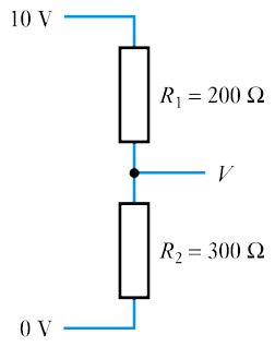
\begin{align*} V &= V_2 + (V_1 - V_2) \frac{ R_2}{R_1 + R_2}\\ &= 10 \frac{ R_2}{R_1 + R_2} \\ &= 10 \frac{ 300}{200 + 300} \\ &= 6V \end{align*}
- 🎥 Watch a video on potential dividers - Adobe Flash video.
Further Study
- The Further Study section at the end of Chapter 1 allows you to test your understanding of simple resistive circuits by considering a simple automotive sub-system.
- Have a look at the problem and then watch the video to see how you did.
- 🎥 Watch a further study video on designing a resistive circuit - Adobe Flash video.
Key Points
- Understanding the next few lectures of this course relies on understanding the various topics covered in this session.
- A clear understanding of the concepts of voltage and current is essential.
- Ohm’s Law and Kirchhoff’s Laws are used extensively in later lectures.
- Experience shows that students have most problems with potential dividers – a topic that is used widely in the next few lectures.
- You are advised to make sure you are happy with this material now.
- ⬇Download chapter 1 tutorial
Exercises
- 1.1 Give the prefixes used to denote the following powers: $ 10^{-12}, 10^{-9}, 10^{-6}, 10^{-3}, 10^{3}, 10^{6}, 10^{9}, 10^{12} $ .
- 1.2 Explain the difference between $1$ ms, $1$ m/s and $1$ mS.
- 1.3 Explain the difference between $1$ m$\Omega$ and $1$ M$\Omega$.
- 1.4 Define the terms ‘direct current’ and ‘alternating current’.
- 1.5 What is the unit of measurement for resistance?
- 1.6 What is the unit of measurement for capacitance?
- 1.7 What is the unit of measurement for inductance?
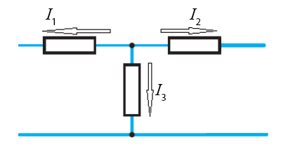
- 1.8 In arrangement (a) $I_1$ = $5$A and $I_2$ = $3$A. Calculate the undefined current $I_3$.
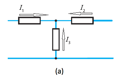
In arrangement (b) $I_2$ = $7$A and $I_3$ = $3$A. Calculate the undefined current $I_1$
- 1.9 Given that $V_1$ = $8$V and $V_2$ = $5$V, calculate the undefined voltage $V_3$ in the following arrangement
- 1.10 If a resistor of $1$ k$\Omega$ has a voltage of $5$ V across it, what is the current flowing through it?
- 1.11 A resistor has $9$ V across it and a current of $1.5$ mA flowing through it. What is its resistance?
- 1.12 A resistor of $25 \Omega$ has a voltage of $25$ V across it. What power is being dissipated by the resistor?
- 1.13 If a $400\Omega$ resistor has a current of $5$ $\mu$A flowing through it, what power is being dissipated by the resistor?
- 1.14 What is the effective resistance of a $20 \Omega$ resistor in series with a $30 \Omega$ resistor?
- 1.15 What is the effective resistance of a $20 \Omega$ resistor in parallel with a $30 \Omega$ resistor?
- 1.16 What is the effective resistance of a series combination of a $1$ k$\Omega$ resistor, a $2.2$ k$\Omega$ resistor and a $4.7$ k$\Omega$ resistor?
- 1.17 What is the effective resistance of a parallel combination of a 1 kΩ resistor, a $2.2$ k$\Omega$ resistor and a $4.7$ k$\Omega$ resistor?
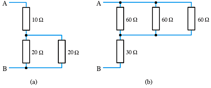
- 1.18 Calculate the effective resistance between the terminals $\text{A}$ and $\text{B}$ in the following arrangements.
- Continues on next tab.
Exercises (cont.)
- 1.19 Calculate the effective resistance between the terminals $\text{A}$ and $\text{B}$ in the following arrangements.
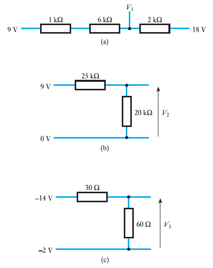
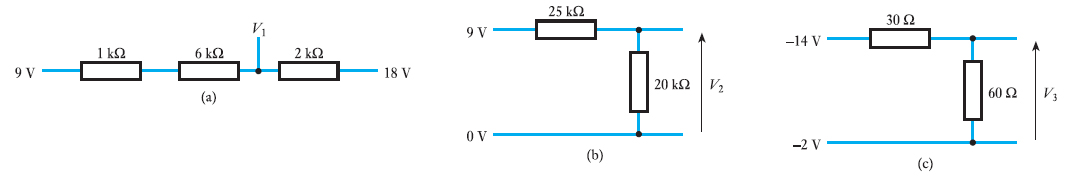
- 1.20 Calculate the voltages $V_1$, $V_2$ and $V_3$ in the following arrangements.
- 1.21 Calculate the voltages $V_1$, $V_2$ and $V_3$ in the following arrangements.
- 1.22 A sinusoidal quantity has a frequency of $1$ kHz. What is its period?
- 1.23 A sinusoidal quantity has a period of $20 \;\mu \text{s}$. What is its frequency?
- ⬇ Tutorial Solutions