Wk 3 & 4
Resistance and DC Circuits
- Introduction
- Current and Charge
- Voltage Sources
- Current Sources
- Resistance and Ohm’s Law
- Resistors in Series and Parallel
- Kirchhoff’s Laws
- Thévenin’s and Norton’s Theorems
- Superposition
- Nodal Analysis
- Mesh Analysis
- Solving Simultaneous Circuit Equations
- Choice of Techniques
Introduction
- Many circuits can be analysed, and in some cases designed, using little more than Ohm’s law.
- However, in some cases we need some additional techniques and these are discussed in this lecture.
- We begin by reviewing some of the basic elements that we use to describe our circuits.
-
Current sources
- We also sometimes use the concept of an ideal current source
– unrealisable, but useful in circuit analysis
– can be a fixed current source, or a controlled or dependent current source
– while an ideal voltage source has zero output resistance, an ideal current source has infinite output resistance
Resistance and Ohm’s Law
- Ohm’s law:
$ V \propto I$
– constant of proportionality is the resistance $R$
– hence
\begin{align*} \large V = IR \quad \; I = \frac{V}{R} \quad \; R = \frac{V}{I} \end{align*}
– current through a resistor causes power dissipation
\begin{align*} \large P = IV \quad \; P = \frac{V^2}{R} \quad \; P = I^2R \end{align*}
Current and Charge
- An electric current is a flow of electric charge
\begin{align*} \large I &= \frac{\large dQ}{dt} \end{align*}- At an atomic level a current is a flow of electrons
– each electron has a charge of:
$ 1.6 \times 10^{-19}$ coulombs– conventional current flows in the opposite direction
- Rearranging above expression gives
\begin{align*} \large Q = \int Idt \end{align*}
- For constant current
\begin{align*} \large Q = I \times t \end{align*}
Voltage Source
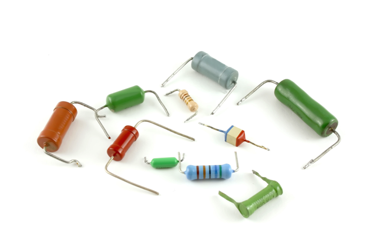
📷 Some voltage sources can be seen here- A voltage source produces an electromotive force ($e.m.f.$) which causes a current to flow within a circuit
– unit of e.m.f. is the volt
– a volt is the potential differencebetween two points when a joule of energy is used to move one coulomb of charge from one point to the other- Real voltage sources, such as batteries have resistance associated with them
– in analysing circuits we use ideal voltage sources
– we also use controlled or dependent voltage sources
- We also sometimes use the concept of an ideal current source
Resistors in parallel
- Resistors in series
_page_10.gif) Click to see the above equation
Click to see the above equation
Kirchhoff’s Laws
- 🎥 Watch a video on Kirchhoff’s Laws - Adobe Flash video
- Node
– a point in a circuit where two or more circuit components are joined- Loop
– any closed path that passes through no node more than once- Mesh
– a loop that contains no other loop- Examples:
– $\text{A, B, C, D, E and F}$ are nodes
– the paths $\text{ABEFA, BCDEB and ABCDEFA}$ are loops
– $\text{ABEFA and BCDEB}$ are meshes- 📷 Example of a node, a loop and a mesh circuit
Resistors
- Resistors
– resistance of a given sample of material is determined by its electrical characteristics and its construction
– electrical characteristics described by its resistivity ρ or its conductivity σ (where σ = 1/ρ)
 $$
\large R = \frac{\rho I}{I}
$$
$$
\large R = \frac{\rho I}{I}
$$
Resistors in Series and Parallel
- Resistors in series
_page_9.gif) Click to see the above equation
Click to see the above equation
_page_11.gif)
- Resistors in series
-
Thévenin’s and Norton’s Theorems
- Thévenin’s Theorem
As far as its appearance from outside is concerned, any two terminal network of resistors and energy sources can be replaced by a series combination of an ideal voltage source $V$ and a resistor $R$, where $V$ is the open-circuit voltage of the network and $R$ is the voltage that would be measured between the output terminals if the energy sources were removed and replaced by their internal resistance- Norton’s Theorem
As far as its appearance from outside is concerned, any two terminal network of resistors and energy sources can be replaced by a parallel combination of an ideal current source $I$ and a resistor $R$, where $I$ is the short-circuit current of the network and $R$ is the voltage that would be measured between the output terminals if the energy sources were removed and replaced by their internal resistance
 – from the Thévenin equivalent circuit$$I_{\large sc} = \frac{\large V_{oc}}{R}$$– hence for either circuit$$R = \frac{V_{\large oc}}{I_{\large sc}}$$
Current Law
- Current Law
At any instant, the algebraic sum of all the currents flowing into any node in a circuit is zero
– if currents flowing into the node are positive, currents flowing out of the node are negative, then $\Sigma I=0$
_page_12_2.gif)
Voltage Law
- Voltage Law
At any instant the algebraic sum of all the voltages around any loop in a circuit is zero
– if clockwise voltage arrows are positive and anticlockwise arrows are negative then $\Sigma V=0$
_page_13.gif)

- Thévenin’s Theorem
- Example (continued)
– if the output is shorted to ground, $R _2$ is in parallel with $R _3$ and the current taken from the source is $30V/15 \; k\Omega = 2mA$. This will divide equally between $R _2$ and $R _3$ so the output current, and so:
$$\large I_{\large sc} = 1mA$$– the resistance in the equivalent circuit is therefore given by:
$$ \large R = \frac{V_{oc}}{I_{sc}} = \frac{15V}{1mA} = 15k \Omega$$– hence equivalent circuits are:
Example
- Example – see Example 3.3 from course text Determine Thévenin and Norton equivalent circuits of the following circuit
 – if nothing is connected across the output no current will flow in $R _2$ so there will be no voltage drop across it. Hence $V_o$ is determined by the voltage source and the potential divider formed by $R _1$ and $R _3$. Hence:
$$\large V_{\large oc} = \frac{30}{2} = 15V$$
- Example (continued)
-
- Example (continued)
– next consider the effect of the $20V$ source alone
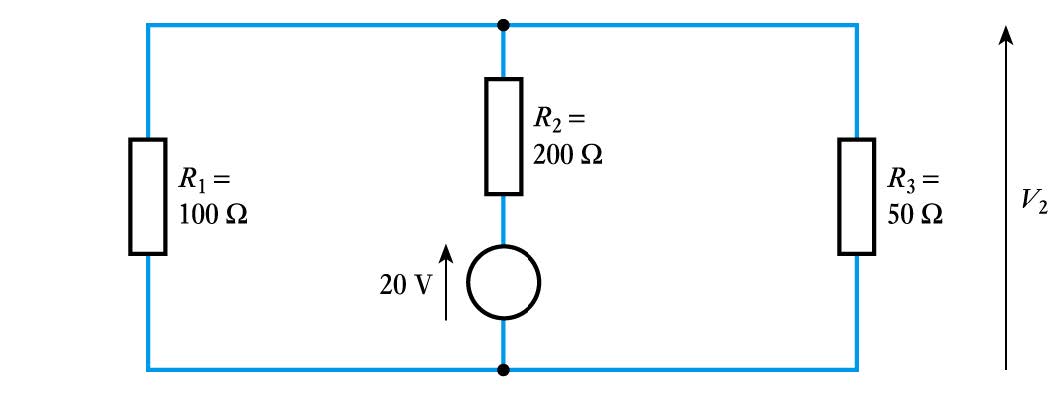 $$V_2 = 20 \frac{100 // 50}{200 + 100 // 50} =20 \frac{33.3}{200+33.3} = 2.86V$$
– so, the output of the complete circuit is the sum of these two voltages
$$V_2 = 20 \frac{100 // 50}{200 + 100 // 50} =20 \frac{33.3}{200+33.3} = 2.86V$$
– so, the output of the complete circuit is the sum of these two voltages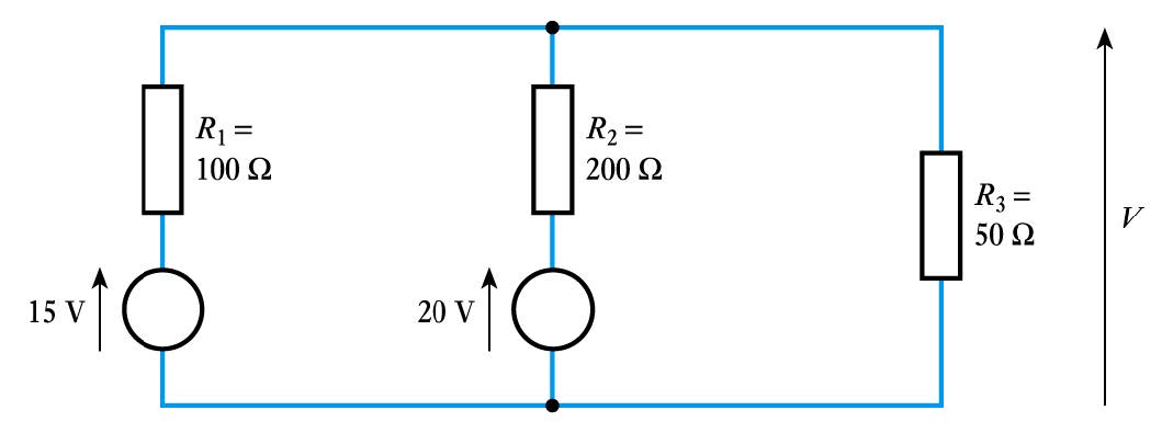 $$V =V_1+V_2 =4.29 + 2.86 = 7.15V$$
Superposition
- Principle of superposition
In any linear network of resistors, voltage sources and current sources, each voltage and current in the circuit is equal to the algebraic sum of the voltages or currents that would be present if each source were to be considered separately. When determining the effects of a single source the remaining sources are replaced by their internal resistance- Example – see Example 3.5 from course text determine the output voltage $V$ of the following circuit
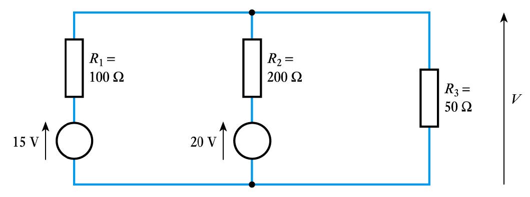
– first consider the effect of the $15V$ source alone
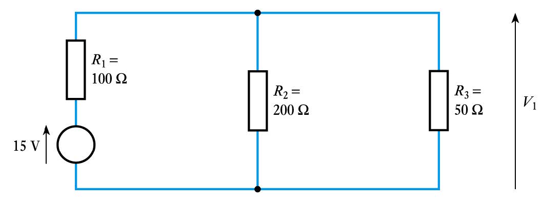 $$V_1 = 15 \frac{200 // 50}{100 + 200 // 50} =15 \frac{40}{100+40} = 4.29V$$
- Example (continued)
-
- Example (continued)
– next we sum the currents flowing into the nodes for which the node voltages are unknown. This gives$$\frac{50 - V_2}{10} + \frac{V_3 -V_2}{20} + \frac{0-V_2}{15} = 0$$ $$\frac{V_2 - V_3}{20} + \frac{100 - V_3}{30} + \frac{0-V_3}{25} = 0$$– solving these two equations gives\begin{align*} V_2 =& 32.34 \;V \\ V_3 =& 40.14 \;V \end{align*}– and the required current is given by$$I_1 = \frac{V_3}{25 \Omega} = \frac{40.14V}{25 \Omega} = 1.6\;A$$Nodal Analysis
- 🎥 Watch a video on nodal analysis - Adobe Flash video
- Six steps:
1. Chose one node as the reference node
2. Label remaining nodes $V_1$, $V_2$ etc.
3. Label any known voltages
4. Apply Kirchhoff’s current law to each unknown node
5. Solve simultaneous equations to determine voltages
6. If necessary calculate required currents- Example – see Example 3.7 from course text Determine the current $I_1$in the following circuit
– first we pick a reference node and label the various node voltages, assigning values where these are known
 $$V_1 = 15 \frac{200 // 50}{100 + 200 // 50} =15 \frac{40}{100+40} = 4.29V$$
- Example (continued)
-
- Example (continued)
– next apply Kirchhoff’s law to each loop. This gives
\begin{align*} E - V_A-V_C-V_F-V_H=& \;0\\ V_C-V_B-V_D+V_E=& \;0 \\ V_F-V_E-V_G-V_J=& \;0 \end{align*}
– which gives the following set of simultaneous equations
\begin{align*} 50 - 70I_1 - 20(I_1-I_2) -30(I_1-I_3) - 40I_1 =& \;0\\ 20(I_1- I_2) - 100I_2 -80I_2 +10(I_3-I_2)=& \;0 \\ 30(I_1-I_3)-10(I_3-I_2)-60I_3 -90I_3=& \;0 \end{align*}
– these can be rearranged to give
\begin{align*} 50 - 160I_1 + 20I_2+30 I_3 =& \;0\\ 20I_1- 210I_2 + 10I_3 =& \;0 \\ 30I_1+10I_2-190I_3=& \;0 \end{align*}
– which can be solved to give
\begin{align*} I_1 =& 326mA \\ I_2 =& 34mA \\ I_3 =& 53mA \end{align*}
– the voltage across the $10 \Omega$ resistor is therefore given by
\begin{align*} V_E =& R_E(I_3-I_2) \\ =& 10(0.053 -0.034) \\ =& 0.19 \; V \end{align*}
– since the calculated voltage is positive, the polarity is as shown by the arrow with the left hand end of the resistor more positive than the right hand endMesh Analysis
- 🎥 Watch a video on mesh analysis - Adobe Flash video
- Four steps:
1. Identify the meshes and assign a clockwise-flowing current to each. Label these $I_1$ $I_2$ etc.
2. Apply Kirchhoff’s voltage law to each mesh
3. Solve the simultaneous equations to determine the currents $I_1$ $I_2$ etc.
4. Use these values to obtain voltages if required- Example – see Example 3.8 from course text determine the voltage across the $10 \Omega$ resistor
– first assign loops currents and label voltages
- Example (continued)
-
Choice of Techniques
- How do we choose the right technique?
– nodal and mesh analysis will work in a wide range of situations but are not necessarily the simplest methods
– no simple rules
– often involves looking at the circuit and seeing
which technique seems appropriateSolving Simultaneous Circuit Equations
- Both nodal analysis and mesh analysis produce a series of simultaneous equations
– can be solved ‘by hand’ or by using matrix methods
\begin{align*} \text {– e.g.} \; 50 - 160I_1 + 20I_2 + 30I_3 =& 0 \qquad\qquad \qquad\qquad\qquad\qquad\qquad\\ 20I_1 - 210I_2 + 10I_3 =& 0 \\ 30I_1 + 10I_2 - 190I_3 =& 0 \end{align*}
– can be rearranged as as
\begin{align*} \; 160I_1 - 20I_2 - 30I_3 =& 50 \qquad\qquad \qquad\qquad\qquad\qquad\qquad\\ 20I_1 - 210I_2 + 10I_3 =& 0 \\ 30I_1 + 10I_2 - 190I_3 =& 0 \end{align*}– these equations can be expressed as \begin{equation} \left[ \begin{array}{cccc} 160 & -20 & -30 \\ 20 & -210 & 10 \\ 30 & 10 & -190 \end{array} \right] \; \left[ \begin{array}{cccc} I_1 \\ I_2 \\ I_3 \end{array} \right] \; = \left[ \begin{array}{cccc} 50 \\ 0 \\ 0 \end{array} \right] \qquad\qquad \end{equation}
– which can be solved by hand (e.g. Cramer’s rule)
– or can use automated tools
• e.g. scientific calculators
• computer-based packages such as MATLAB or Mathcad - How do we choose the right technique?
-
Further Study
- 🎥 Watch a further study video on selecting circuit analysis techniques - Adobe Flash video
- The Further Study section at the end of Chapter 3 investigates the choice of circuit analysis techniques.
- A circuit is presented which could be analysed in a number of ways.
- Have a look and see which you think is best, then watch the video at the link at the top of the page.
Key Points
- An electric current is a flow of charge
- A voltage source produces an e.m.f. which can cause a current to flow
- Current in a conductor is directly proportional to voltage
- At any instant the sum of the currents into a node is zero
- At any instant the sum of the voltages around a loop is zero
- Any two terminal network of resistors and energy sources can be replaced by a Thévenin or Norton equivalent circuit
- Nodal and mesh analysis provide systematic methods of applying Kirchhoff’s laws
-
- 3.10 Determine the resistance of each of the following combinations.
- 3.11 What resistance corresponds to 10 kΩ//10 kΩ?
- 3.12 Define the terms ‘node’, ‘loop’ and ‘mesh’.
- 3.13 Label each of the nodes in the following arrangement with the letters $A, B, C$ etc
- 3.14 Having labelled each of the nodes in the previous exercise, use these labels to define each of the loops within the circuit and each of the meshes.
- ⬇Download chapter 3 tutorial
Exercises
- 3.1 Write down an equation relating current and charge.
- 3.2 What quantity of charge is transferred if a current of 5 A flows for 10 seconds?
- 3.3 What is the internal resistance of an ideal voltage source?
- 3.4 What is meant by a controlled voltage source?
- 3.5 What is the internal resistance of an ideal current source?
- 3.6 Determine the voltage V in each of the following circuits, being careful to note its polarity in each case.
- 3.7 For each circuit in Exercise 3.6, determine the power dissipated in the resistor.
- 3.8 Estimate the resistance of a copper wire with a cross-sectional area of 1 mm2 and a length of 1 m at 20 °C.
(resistivity of copper at 20 degrees is 1.68 x 10^-8 ohm m)- 3.9 What is the relationship between the conductivity of a material and its resistivity ?
-
- 3.18 A two-terminal network is investigated by measuring the output voltage when connected to different loads. When a resistance of $12 \Omega$ is connected across the output the output voltage is $16 \; V$, and when a load of $48 \Omega$ is connected the output voltage is $32 \; V$. Use a graphical method to determine the Thévenin and Norton equivalent circuits of this arrangement.
- 3.19 Repeat Exercise 3.18 using a non-graphical approach.
- 3.20 The Thévenin equivalent circuit of an arrangement consists of a voltage source of $10 \; V$ in series with a resistance of $100 \Omega$. What would be an appropriate Norton equivalent circuit?
- 3.21 The Norton equivalent circuit of an arrangement consists of a current source of $25 \; mA$ in parallel with a resistance of $2.5 \; k \Omega$. What would be an appropriate Thévenin equivalent circuit?
- 3.22 Use the principle of superposition to determine the voltage $V$ in each of the following circuits.
Exercises (cont)
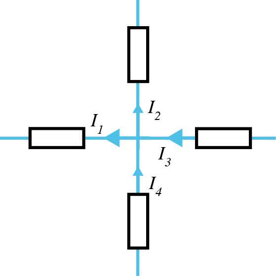
- 3.15 Given that $I_1= 6A, I_3 = 8 A \; \text{and} \; I_4 = 5 A$ determine the magnitude of $I_2$ in the following circuit.
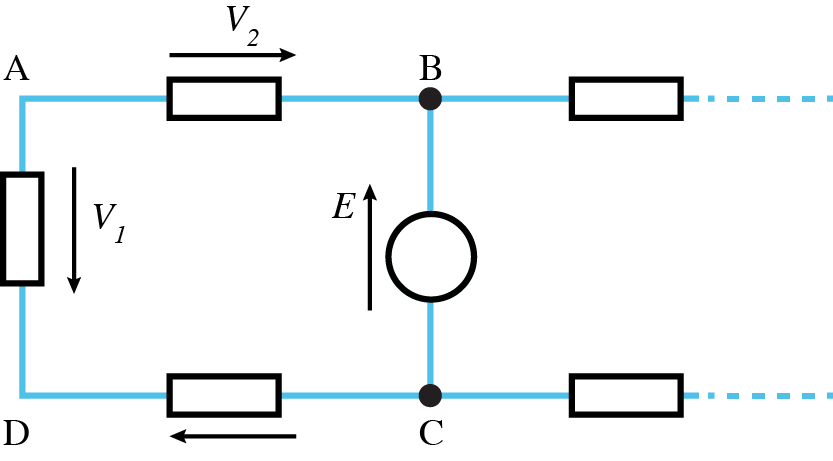
- 3.16 Given that $V_1 = 2V, V_3 = 4V \; \text{and} \; E = 12V A$ , determine the magnitude of $V_2$ in the following circuit.
- 3.17 Derive Thévenin and Norton equivalent circuits for the following arrangements.
-
- 3.27 Use mesh analysis to determine the voltage $V$ in the following circuit.
- 3.28 Use mesh analysis to determine the current $I$ in the following circuit.
- 3.29 Use an appropriate form of analysis to determine the voltage $V_0$ in the following circuit.
- ⬇ Tutorial Solutions
Exercises (cont)
- 3.23 Use nodal analysis to determine the voltage $V$ in the following circuit.
- 3.24 Use nodal analysis to determine the current $I_1$ in the following circuit.
- 3.25 Use nodal analysis to determine the current $I_1$ in the following circuit.
- 3.26 Use mesh analysis to determine the voltage $V$ in the following circuit.