Wk 5
Capacitance and Electric Fields
- Introduction
- Capacitors and Capacitance
- Alternating Voltages and Currents
- The Effect of a Capacitor’s Dimensions
- Electric Fields
- Capacitors in Series and Parallel
- Voltage and Current
- Sinusoidal Voltages and Currents
- Energy Stored in a Charged Capacitor
- Circuit Symbols
Introduction
- We noted earlier that an electric current represents a flow of charge
- A capacitor can store electric charge and can therefore store electrical energy
- Capacitors are often used in association with alternating currents and voltages
- They are a key component in almost all electronic circuits
- They are a key component in almost all electronic circuits
📷 Show Circuit Symbols
-
(continued)
- For a given capacitor the stored charge q is directly proportional to the voltage across it $V$
- The constant of proportionality is the capacitance $C$ and thus
\begin{align*} \large C &= \frac{\large Q}{V} \end{align*}- If the charge is measured in coulombs and the voltage in volts, then the capacitance is in farads
- Example – see Example 4.1 in course text. A 10 μF capacitor has 10 V across it. What quantity of charge is stored in it?
From above: \begin{align*} \large C &= \frac{\large Q}{V} \\ Q &= CV\\ &= 10\; ^5. 10\\ &= 100 \; \mu C \end{align*} - For a given capacitor the stored charge q is directly proportional to the voltage across it $V$
The Effect of a Capacitor’s Dimensions
- The capacitance of a capacitor is directly proportional to its area $A$, and inversely proportional to the distance between its plates d. Hence $$ \large C \; \propto \; A/d$$
– the constant of proportionality is the permittivity ε of the dielectric
– the permittivity is normally expressed as the product of the absolute permittivity ε0 and the relative permittivity εr of the dielectric used\begin{align*} \large C &= \frac{\large \varepsilon A}{d} = \frac{\large \varepsilon _0 \varepsilon _r A}{d} \end{align*}Alternating Voltages and Currents
- A constant current cannot flow through a capacitor
– however, since the voltage across a capacitor is proportional to the charge on it, an alternating voltage must correspond to an alternating charge, and hence to current flowing into and out of the capacitor
– this can give the impression that an alternating current flows through the capacitor
- A mechanical analogy may help to explain this
– consider a window - air cannot pass through it, but sound (which is a fluctuation in air pressure) can
_page_11.gif)
- The capacitance of a capacitor is directly proportional to its area $A$, and inversely proportional to the distance between its plates d. Hence $$ \large C \; \propto \; A/d$$
- The force between positive and negative charges is described in terms of the electric flux linking them
– measured in coulombs (as for electric charge)
– a charge $Q$ will produce a total flux of $Q$ coulombs- We also define the electric flux density $D$ as the flux per unit area
- In a capacitor we can almost always ignore edge effects, and
\begin{align*} \large D &= \frac{\large Q}{A} \end{align*}
- Combining the earlier equations it is relatively easy to show that
\begin{align*} \Large \varepsilon &= \frac{\large D}{E} \end{align*}
- Thus the permittivity of the dielectric within a capacitor is equal to the ratio of the electric flux density to the electric field strength
Electric Fields
- The charge on the capacitor produces an electric field with an electric field strength E given by
\begin{align*} \large E &= \frac{\large V}{d} \end{align*}
the units of $E$ are volts/metre $(V/m)$
- All insulating materials have a maximum value for the field strength that they can withstand
– the dielectric strength $E_m$- To produce maximum capacitance for a given size of capacitor we want d to be as small as possible
– however, as $d$ is decreased the electric field $E$ is increased
– if $E$ exceed $E_m$ the dielectric will- break down
– there is therefore a compromise between physical size and breakdown voltage

- The force between positive and negative charges is described in terms of the electric flux linking them
-
- Capacitors in series
– consider a voltage $V$ applied across two capacitors in series
– the only charge that can be applied to the lower plate of $C_1$ is that supplied by the upper plate of $C_2$. Therefore the charge on each capacitor must be identical. Let this be $Q$, and therefore if a single capacitor $C$ has the same effect as the pair, then\begin{align*} V =& V_1 + V_2 \\ \frac{Q}{C} =& \frac{Q}{C_1} + \frac{Q}{C_2} \\ \frac{1}{C}=& \frac{1}{C_1} + \frac{1}{C_2} \end{align*}Capacitors in Series and Parallel
- 🎥 Watch a video on capacitors in series and in parallel - Adobe Flash video
- Capacitors in parallel
– consider a voltage V applied across two capacitors
– then the charge on each is \begin{align*}Q_1 = VC_1 \qquad Q_2 = VC_2\end{align*}– if the two capacitors are replaced with a single capacitor $C$ which has a similar effect as the pair, then
\begin{align*} \text{Charge stored on }C =& Q_1 + Q_2 \\ VC =& VC_1 + VC_2 \\ C=& C_1 + C_2 \end{align*} - Capacitors in series
-
(cont.)
– as the capacitor charges:$V_C$ increases
$V_R$ decreases
hence $I$ decreases
we have exponential behaviour
- Time constant
– charging current is determined by $R$ and the voltage across it
– increasing $R$ will increase the time taken to charge $C$
– increasing $C$ will also increase time taken to charge $C$
– time required to charge to a particular voltage is determined by the product $CR$
– this product is the time constant T (greek tau)- See Computer Simulation Exercises 4.1 and 4.2 in the course text
Voltage and Current
- The voltage across a capacitor is directly related to the charge on the capacitor
\begin{align*} \large V &= \frac{\large Q}{C} = \frac{1}{C} Idt \end{align*}
- Alternatively, since Q = CV we can see that \begin{align*} \frac{ dQ}{dt} = C\frac{dV}{dt} \end{align*}
and since dQ/dt is equal to current, it follows that
\begin{align*} \large I &= C\frac{dV}{dt} \end{align*}
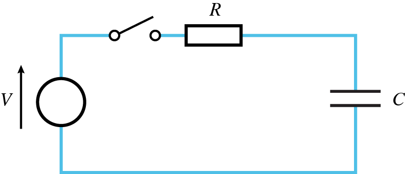
- Consider the circuit shown here
– capacitor is initially discharged
voltage across it will be zero– switch is closed at $t = 0$– $V_C$ is initially zero
hence $V_R$ is initially $V$
hence $I$ is initially $V/R$
- Time constant
-
Energy Stored in a Charged Capacitor
- To move a charge $Q$ through a potential difference $V$ requires an amount of energy $QV$
- As we charge up a capacitor we repeatedly add small amounts of charge $ \Delta Q$ by moving them through a voltage equal to the voltage on the capacitor
- Since $Q = CV$, it follows that $ \Delta Q = C\Delta V$, so the energy needed $E$ is given by
\begin{align*} \large E = ^V_0 CVdV = \frac{1}{2}CV^2 \end{align*}
- Alternatively, since $V = Q/C$
\begin{align*} \large E = \frac{1}{2} CV^2 = \frac{1}{2} C\frac{\;Q \; ^2}{C} = \frac{1}{2} \frac{Q^2}{C} \end{align*}
- Example – see Example 4.7 in the course text Calculate the energy stored in a $10 \mu F$ capacitor when it is charged to $100 V$
From above:
\begin{align*} \large E = \frac{1}{2} CV^2 = \frac{1}{2} \cdot 10 \; ^5 \cdot 100^2 = 50 \; mJ \end{align*}
Sinusoidal Voltages and Currents
- Consider the application of a sinusoidal voltage to a capacitor
– from above $I = C \; dV/dt$
– current is directly proportional to the differential of the voltage
– the differential of a sine wave is a cosine wave
– the current is phase-shifted by 90° with respect to the voltage
- Since $I = C \; dV/dt$ the magnitude of the current is related to the rate of change of the voltage
– in sinusoidal voltages the rate of change is determined by the frequency
– hence capacitors are frequency dependent in their characteristics- We will return to look at frequency dependence in later lectures.
-
Further Study
- 🎥 Watch a further study video on energy storage in parallel capacitors - Adobe Flash video
- The Further Study section at the end of Chapter 4 looks at the energy stored within capacitors and considers what happens when two charge capacitors are joined together.
- Do the sums yourself, then watch the video to check your calculations.
- We begin by reviewing some of the basic elements that we use to describe our circuits.
Key Points
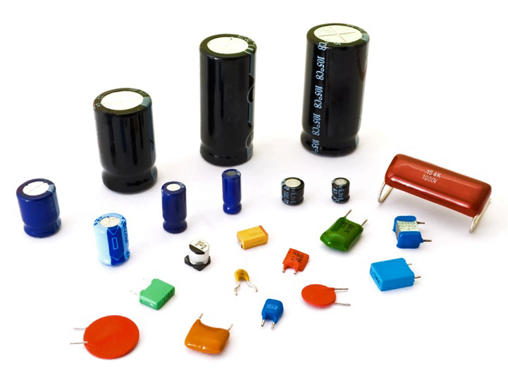
- A capacitor consists of two plates separated by a dielectric
- The charge stored on a capacitor is proportional to V
- A capacitor blocks DC but appears to pass AC
- The capacitance of several capacitors in parallel is equal to the sum of their individual capacitances
- The capacitance of several capacitors in series is equal to the reciprocal of the sum of the reciprocals of the individual capacitances
- In AC circuits current leads voltage by 90° in a capacitor
- The energy stored in a capacitor is ½ $CV^2$ or ½ $Q^2 /C$
-
- 4.10 Why does a capacitor appear to pass AC signals while blocking DC signals?
- 4.11 How is the capacitance of a parallel-plate capacitor related to its dimensions?
- 4.12 The conducting plates of a capacitor are 5 × 15 mm and have a separation of $10 \; \mu m$. What would be the capacitance of such a device if the space between the plates were filled with air?
- 4.13 What would be the capacitance of the device described in Exercise 4.10 if the space between the plates were filled with a dielectric with a relative permittivity of $200$?
- 4.14 What is meant by stray capacitance, and why is this sometimes a problem?
- ⬇Download chapter 4 tutorial
Exercises
- 4.1 Explain what is meant by a dielectric.
- 4.2 If electrons represent negative charge in a capacitor, what constitutes positive charge?
- 4.3 If the two plates of a capacitor are insulated from each other, why does it appear that under some circumstances a current flows between them?
- 4.4 Why does the presence of charge on the plates of a capacitor represent the storage of energy?
- 4.5 How is the voltage across a capacitor related to the stored charge?
- 4.6 What are the units of measurement of capacitance?
- 4.7 A $100 \; \mu F$ capacitor has $5 V$ across its terminals. What quantity of charge is stored in it?
- 4.8 A $22 \; \mu F$ capacitor holds $1 \; mC$ of stored charge. What voltage is seen across its terminals?
- 4.9 A capacitor has a voltage of 25 $V$ across it when it holds $500 \; \mu C$ of charge. What is its capacitance?
-
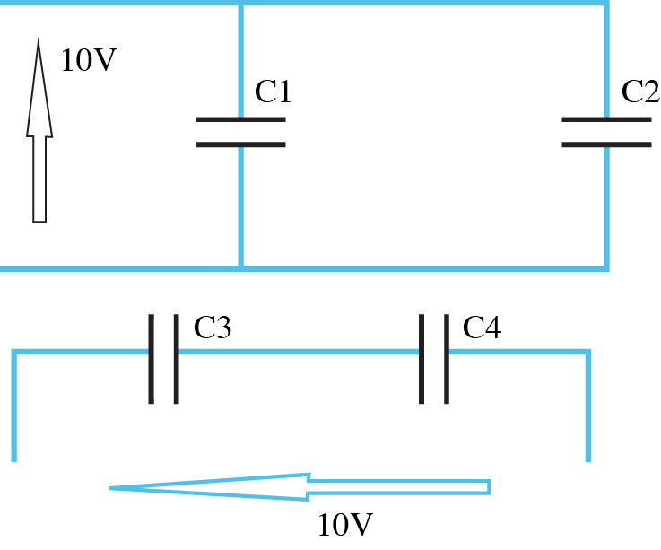
- 4.22 Determine the charge stored in the capacitors $C1, C2, C3$ and $C4$ in the arrangements shown in exercise 4.21.
- 4.23 How is voltage related to current in a capacitor?
- 4.24 Explain what is meant by a time constant. Given that $R = 50 \; k\Omega \text{ and } C = 10 \mu F$, what is the time constant of the following arrangement?
- 4.25 If the resistor in the circuit of Exercise 4.24 was increased by a factor of $10 \text{ to } 500 \; k\Omega$, what value of capacitor would be required to leave the time constant of the circuit unchanged?
- 4.26 Describe the relationship between the voltage across a capacitor and the current if the voltage is sinusoidal.
- 4.27 Give an expression for the energy stored in a charged capacitor.
- 4.28 A $5 \; mF$ capacitor is charged to $15 \; V$. What is the energy stored in the capacitor?
- 4.29 A $50 \; \mu F$ capacitor contains $1.25 \; mC$ of charge. What energy is stored in the capacitor?
- ⬇ Tutorial Solutions
Exercises (cont.)
- 4.15 Explain what is meant by an electric field and by electric field strength.
- 4.16 The plates of a capacitor have $250 \; V$ across them and have a separation of $15 \mu m$. What is the electric field strength in the dielectric?
- 4.17 What is meant by dielectric strength?
- 4.18 Explain what is meant by electric flux and by electric flux density.
- 4.19 The plates of a capacitor are 15 × 35 mm and store a charge of $35 \mu C$. Calculate the electric flux density in the dielectric.
- 4.20 Determine the effective capacitance of each of the following arrangements.
- 4.21 $\text{Given that } C_1 = 10 \; \mu F, C_2 = 20 \; \mu F, \\ C_3 = 10 \; \mu F \text{ and } C_4 = 20 \; \mu F$ determine the voltages across the capacitors in the following arrangements.