Wk 6
Inductance and Magnetic Fields
- Introduction
- Electromagnetism
- Reluctance
- Inductance
- Self-inductance
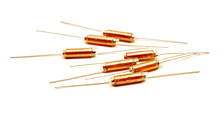
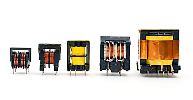
- Inductors
- Inductors in Series and in Parallel
- Voltage and Current
- Sinusoidal Voltages and Currents
- Energy Storage in an Inductor
- Mutual Inductance
- Transformers
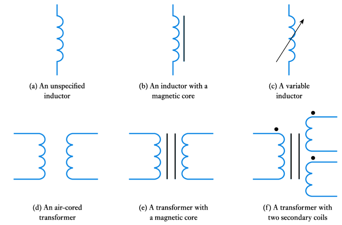
- Circuit Symbols
- The Use of Inductance in Sensors
Introduction
- Earlier we noted that capacitors store energy by producing an electric field within a piece of dielectric material
- Inductors also store energy, in this case it is stored within a magnetic field
- In order to understand inductors, and related components such as transformers, we need first to look at electromagnetism
-
Example (cont.)
- Adding a ferromagnetic ring around a wire will increase the flux by several orders of magnitude - since $\large \mu _r$ for ferromagnetic materials is 1000 or more
- When a current-carrying wire is formed into a coil the magnetic field is concentrated
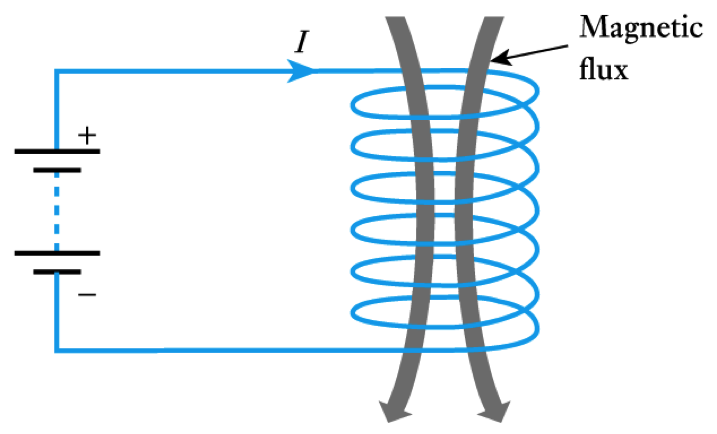
- For a coil of $N$ turns the m.m.f. ($F$) is given by
\begin{align*} \large F = IN \end{align*}and the field strength is\begin{align*} \large F = \frac{IN}{l} \end{align*}
- The magnetic flux produced is determined by the permeability of the material present
- a ferromagnetic material will increase the flux density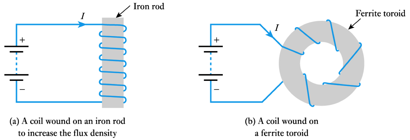
Electromagnetism
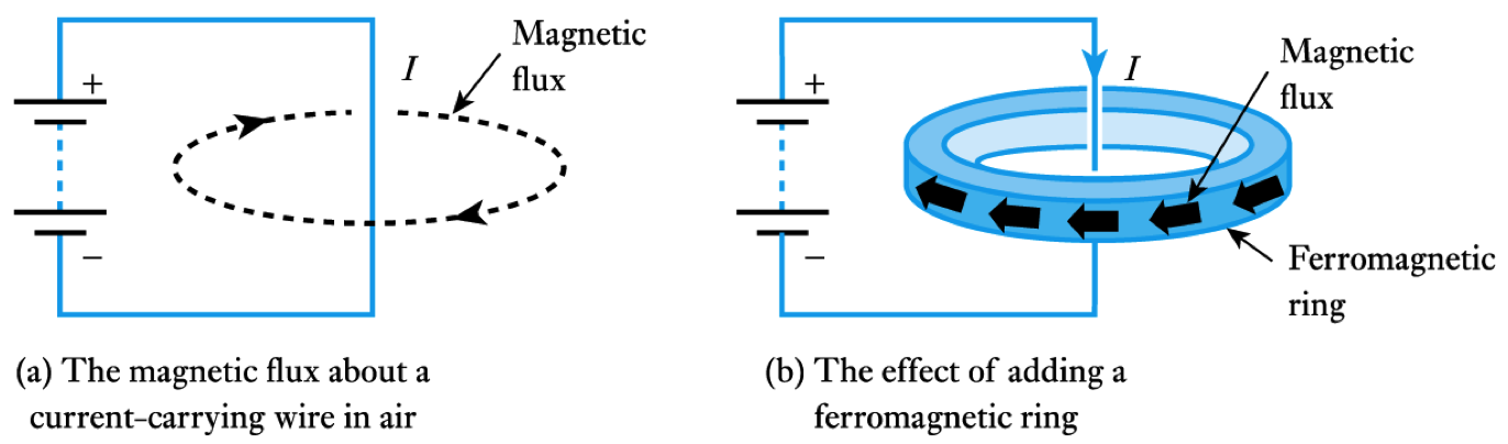
- A wire carrying a current $I$ causes a magnetomotive force ($\; m.m.f \;$) $F$
– this produces a magnetic field
– F has units of Amperes
– for a single wire $F$ is equal to $I$
- The magnitude of the field is defined by the magnetic field strength, $H$, where
where l is the length of the magnetic circuit\begin{align*} \large H = \frac{I}{l} \end{align*}
- Example – see Example 5.1 from course text A straight wire carries a current of $5 \; A$. What is the magnetic field strength $H$ at a distance of 100mm from the wire? Magnetic circuit is circular. $r = 100mm$, so path = $2\pi r = 0.628m$
\begin{align*} \large H &= \frac{\large I}{l} = \frac{\large 5}{0.628} = 7.96 \; \text{A/m} \end{align*}- The magnetic field produces a magnetic flux, $\phi$
- flux has units of weber (Wb)
- Strength of the flux at a particular location is measured in term of the magnetic flux density, B
- flux density has units of tesla (T) (equivalent to 1 Wb/m2)- Flux density at a point is determined by the field strength and the material present
\begin{align*} \large B = \mu H \; \text{ or } \; B = \mu _0 \mu _r H \end{align*}where $\large \mu _r$ is the permeability of the material, $ \large \mu _r$ is the relative permeability and $\large \mu_0$ is the permeability of free space
- Adding a ferromagnetic ring around a wire will increase the flux by several orders of magnitude - since $\large \mu _r$ for ferromagnetic materials is 1000 or more
-
Inductors
- The inductance of a coil depends on its dimensions and the materials around which it is formed
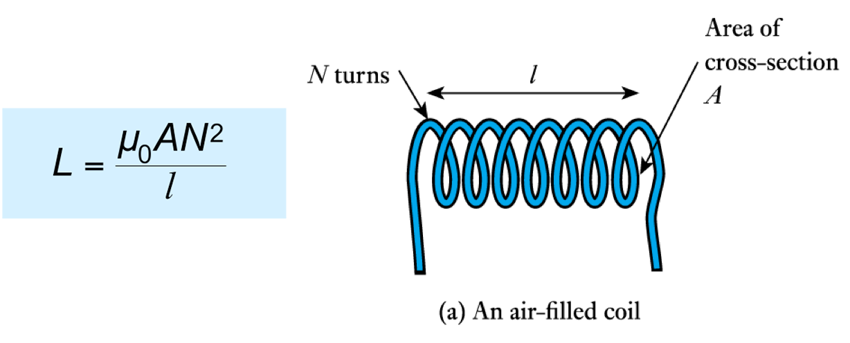
Click to see the equation above.
- The inductance is greatly increased through the use of a ferromagnetic core, for example
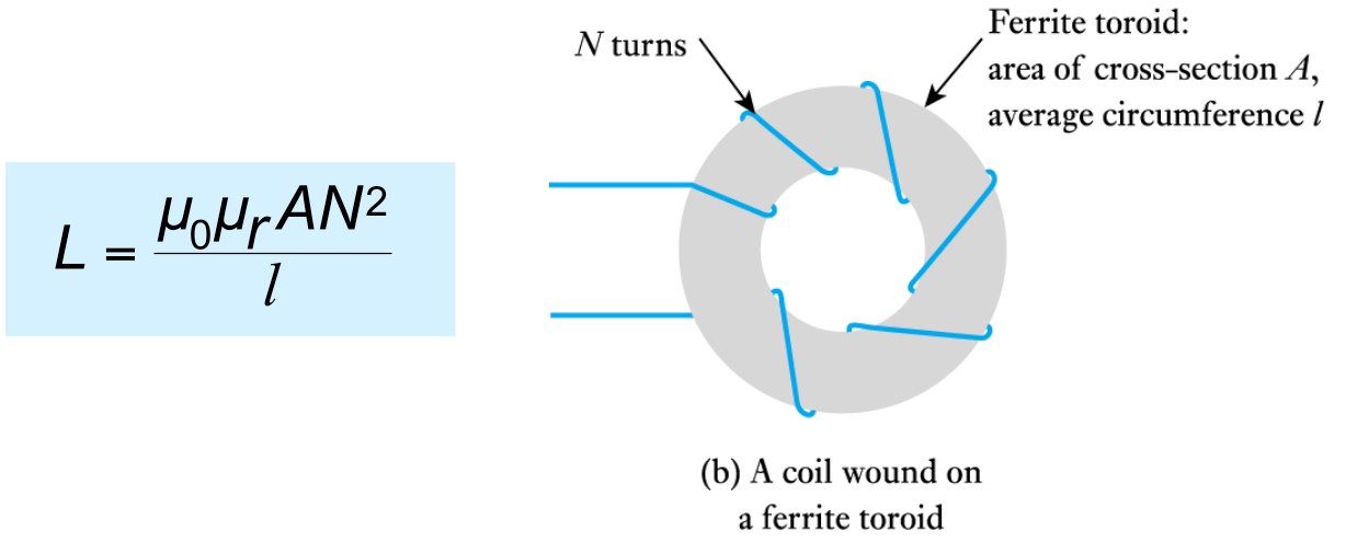
Click here to see the equation.
- Equivalent circuit of an inductor
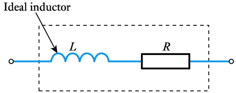
- All real circuits also possess stray capacitance
Reluctance
- In a resistive circuit, the resistance is a measure of how the circuit opposes the flow of electricity
- In a magnetic circuit, the reluctance, $S$ is a measure of how the circuit opposes the flow of magnetic flux
- In a resistive circuit $R = V/I$
- In a magnetic circuit
\begin{align*} \large S = \frac{F}{\phi} \end{align*}
- the units of reluctance are amperes per weber (A/ Wb)Inductance
- A changing magnetic flux induces an e.m.f. in any conductor within it
- Faraday’s law: The magnitude of the e.m.f. induced in a circuit is proportional to the rate of change of magnetic flux linking the circuit
- Lenz’s law: The direction of the e.m.f. is such that it tends to produce a current that opposes the change of flux responsible for inducing the e.m.f.
- When a circuit forms a single loop, the e.m.f. induced is given by the rate of change of the flux
- When a circuit contains many loops the resulting e.m.f. is the sum of those produced by each loop
- Therefore, if a coil contains $N$ loops, the induced voltage $V$ is given by
\begin{align*} \large V = N \frac{d \phi}{dt} \end{align*}
where $d \phi / dt$ is the rate of change of flux in Wb/s- This property, whereby an e.m.f. is induced as a result of changes in magnetic flux, is known as inductance
Self-inductance
- A changing current in a wire causes a changing magnetic field about it
- A changing magnetic field induces an e.m.f. in conductors within that field
- Therefore when the current in a coil changes, it induces an e.m.f. in the coil
- This process is known as self-inductance
\begin{align*} \large V = L \frac{d I}{dt} \end{align*}
where $L$ is the inductance of the coil (unit is the Henry) - The inductance of a coil depends on its dimensions and the materials around which it is formed
-
- Time constant
– we noted earlier that in a capacitor-resistor circuit the time required to charge to a particular voltage is determined by the time constant $CR$
– in this inductor-resistor circuit the time taken for the current to rise to a certain value is determined by L/R
– this value is again the time constant $\text{T}$ (greek tau)
- See Computer Simulation Exercises 5.1 and 5.2 in the course text
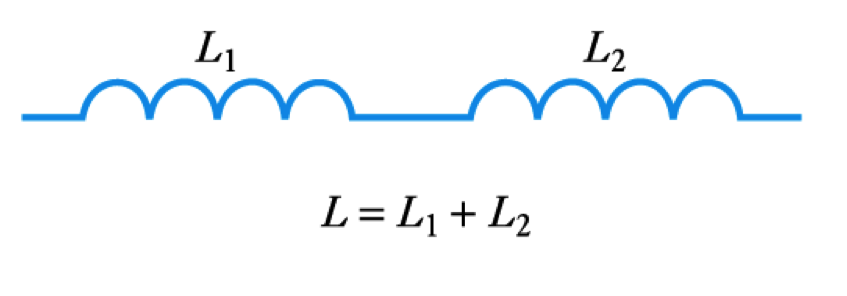
Inductors in Series and Parallel
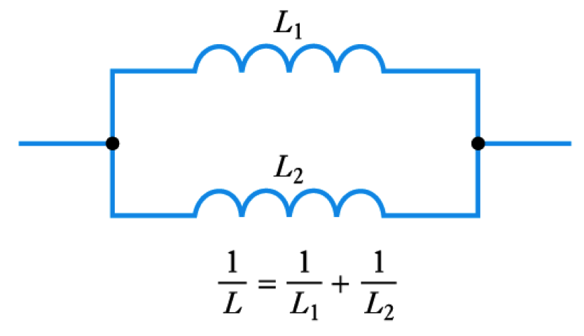
- When several inductors are connected together their effective inductance can be calculated in the same way as for resistors – provided that they are not linked magnetically
- Inductors in Series
- Inductors in Parallel
Voltage and Current
- 📷 Consider the circuit shown here
– inductor is initially un-energised
current through it will be zero
– switch is closed at $t = 0$
– $I$ is initially zero
hence $V _R$ is initially $0$
hence $V _L$ is initially $V$
– as the inductor is energised:
$I$ increases
$V _R$ increases
hence $V _L$ decreases
we have exponential behaviour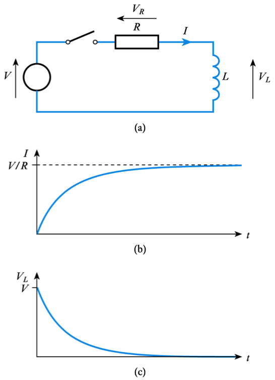
- Time constant
-
Energy Storage in an Inductor
- Can be calculated in a similar manner to the energy stored in a capacitor
- In a small amount of time dt the energy added to the magnetic field is the product of the instantaneous voltage, the instantaneous current and the time
\begin{align*} \text{Energy added } = vidt = L \frac {di}{dt} idt = Lidi \end{align*}- Thus, when the current is increased from zero to I
\begin{align*} \large E = L \int_{0}^{I} idt = \frac{1}{2} LI^2 \end{align*}Sinusoidal Voltages and Currents
- Consider the application of a sinusoidal current to an inductor
– from above $V = L \; dI/dt$
– voltage is directly proportional to the differential of the current
– the differential of a sine wave is a cosine wave
– the voltage is phase-shifted by 90° with respect to the current
– the phase-shift is in the opposite direction to that in a capacitor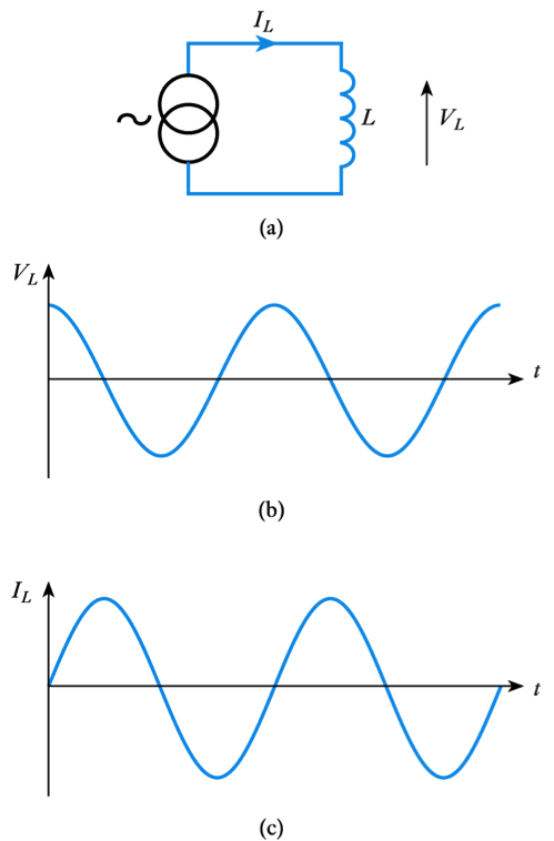
-
Transformers
- 🎥 Watch a video on transformers - Adobe Flash video
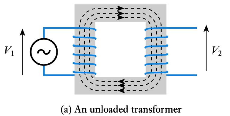
- Most transformers approximate to ideal components
– that is, they have a coupling coefficient ≈ 1
– for such a device, when unloaded, their behaviour is determined by the turns ratio
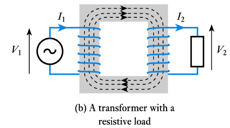
- When used with a resistive load, current flows in the secondary
– this current itself produces a magnetic flux which opposes that produced by the primary
– thus, current in the secondary reduces the output voltage
Mutual Inductance
- When two coils are linked magnetically then a changing current in one will produce a changing magnetic field which will induce a voltage in the other
– this is mutual inductance- When a current I1 in one circuit, induces a voltage V2 in another circuit, then
\begin{align*} \large V_2 = M \frac{\;dI_1}{dt} \end{align*}
where $M$ is the mutual inductance between the circuits. The unit of mutual inductance is the Henry (as for self-inductance)- The coupling between the coils can be increased by wrapping the two coils around a core
– the fraction of the magnetic field that is coupled is referred to as the coupling coefficient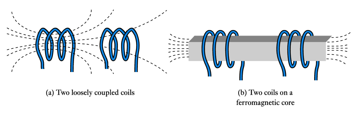
- Coupling is particularly important in transformers
– the arrangements below give a coupling coefficient that is very close to $1$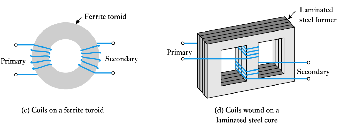
-
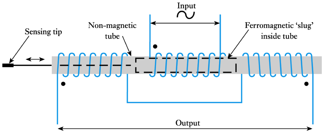
- Linear variable differential transformers (LVDTs)
The Use of Inductance in Sensors
- 🎥 Watch a video on the applications of inductive sensors - Adobe Flash video
- 📷 Show circuit symbols
- Numerous examples:
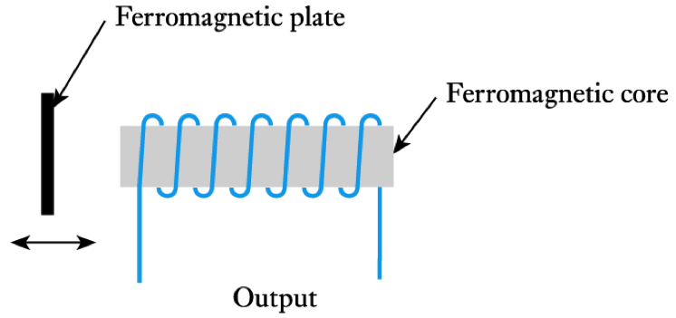
- Inductive proximity sensors
– basically a coil wrapped around a ferromagnetic rod
– a ferromagnetic plate coming close to the coil changes its inductance allowing it to be sensed
-
Key Points
- Inductors store energy within a magnetic field
- A wire carrying a current creates a magnetic field
- A changing magnetic field induces an electrical voltage in any conductor within the field
- The induced voltage is proportional to the rate of change of the current
- Inductors can be made by coiling wire in air, but greater inductance is produced if ferromagnetic materials are used
- The energy stored in an inductor is equal to ½ $LI^2$
- When a transformer is used with alternating signals, the voltage gain is equal to the turns ratio
-
- 5.12 Explain what is meant by inductance.
- 5.13 Explain what is meant by self-inductance.
- 5.14 How is the voltage induced in a conductor related to the rate of change of the current within it?
- 5.15 Define the henry as it applies to the measurement of self-inductance.
- 5.16 The current in an inductor changes at a constant rate of $50 mA/s$, and there is a voltage across it of $150$ $\mu V$. What is its inductance?
- 5.17 Why does the presence of a ferromagnetic core increase the inductance of an inductor?
- 5.18 Calculate the inductance of a helical, air-filled coil $500 mm$ in length, with a cross-sectional area of $40 mm ^2$ and having $600$ turns.
- 5.19 Calculate the inductance of a coil wound on a ferromagnetic toroid of $300 mm$ mean circumference and $100 mm^2$ cross-sectional area, if there are $250$ turns on the coil and the relative permeability of the toroid is $800$.
- 5.20 How does a real inductor differ from an ideal component?
- 5.21 Why do all conductors introduce amounts of stray inductance into circuits?
- ⬇Download chapter 5 tutorial
Exercises
- 5.1 Explain what is meant by a magnetomotive force (m.m.f.).
- 5.2 Describe the field produced by a current flowing in a straight wire.
- 5.3 A straight wire carries a current of $3 A$. What is the magnetic field at a distance of 1 m from the wire? What is the direction of this field?
- 5.4 What factors determine the flux density at a particular point in space adjacent to a current-carrying wire?
- 5.5 Explain what is meant by the permeability of free space. What are its value and units?
- 5.6 Explain what is meant by relative permeability. What are its value and units? What would be typical values for this quantity for non-magnetic and ferromagnetic materials?
- 5.7 Give an expression for the magnetomotive force produced by a coil of $N$ turns that is passing a current of $I$ amperes.
- 5.8 A coil is formed by wrapping wire around a wooden toroid. The cross-sectional area of the coil is $400mm^2$, the number of turns is $600$, and the mean circumference of the toroid is $900mm$. If the current in the coil is $5A$, calculate the magnetomotive force, the magnetic field strength in the coil, the flux density in the coil and the total flux.
- 5.9 If the toroid in Exercise 5.8 were to be replaced by a ferromagnetic toroid with a relative permeability of $500$, what effect would this have on the values calculated?
- 5.10 If an m.m.f. of $15$ ampere-turns produces a total flux of 5 mWb, what is the reluctance of the magnetic circuit?
- 5.11 State Faraday’s law and Lenz’s law.
-
- 5.28 Discuss the implications of induced voltages when switching inductive circuits.
- 5.29 What is the relationship between the sinusoidal current in an inductor and the voltage across it?
- 5.30 What is the energy stored in an inductor of 2 mH when a current of 7 A is passing through it?
- 5.31 Explain what is meant by mutual inductance.
- 5.32 Define the henry as it applies to the measurement of mutual inductance.
- 5.33 What is meant by a coupling coefficient?
- 5.34 What is meant by the turns ratio of a transformer?
- 5.35 A transformer has a turns ratio of 10. A sinusoidal voltage of 5 V peak is applied to the primary coil, with the secondary coil open circuit. What voltage would you expect to appear across the secondary coil?
- 5.36 What would be the effect of adding a resistor across the secondary coil of the transformer in the arrangement described in Exercise 5.35?
- 5.37 What is meant by a step-up transformer?
- 5.38 What is meant by a step-down transformer?
- 5.39 Explain the dot notation used when representing transformers in circuit diagrams.
- 5.40 Describe the operation of an inductive proximity sensor.
- 5.41 Describe the construction and operation of an LVDT.
- ⬇ Tutorial Solutions
Exercises (cont.)
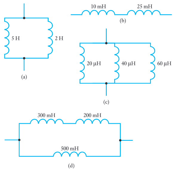
- 5.22 Calculate the effective inductance of the following arrangements.
- 5.23 Describe the relationship between voltage and current in an inductor.
- 5.24 A constant current of 3 A is passed through a 12 H inductor. What voltage will be produced across the component?
- 5.25 Why is it not possible for the current in an inductor to change instantaneously?
- 5.26 Explain what is meant by a time constant. What is the time constant of a series LR circuit with R = 50Ω and L = 100 mH?
- 5.27 If the resistor in Exercise 5.26 is increased by a factor of 10, to 500Ω, what value of inductor would be required to leave the time constant of the circuit unchanged?