Wk 8
Power in AC Circuits
- Introduction
- Power in Resistive Components
- Power in Capacitors
- Power in Inductors
- Circuits with Resistance and Reactance
- Active and Reactive Power
- Power Factor Correction
- Three-Phase Systems
- Power Measurement
Introduction
- The instantaneous power dissipated in a component is a product of the instantaneous voltage and the instantaneous current $p = vi$
- In a resistive circuit the voltage and current are in phase – calculation of $p$ is straightforward
- In reactive circuits, there will normally be some phase shift between $v$ and $i$, and calculating the power becomes more complicated
-
Power in Capacitors
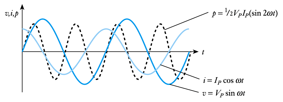
- From our discussion of capacitors we know that the current leads the voltage by $90 ^\circ$. Therefore, if a voltage $v = V_P \text{ sin } ωt$ is applied across a capacitance $C$, the current will be given by $i$ = $I _p \text{ cos } ωt$
Then \begin{align*} p &= vi \\ &= V_P \text{ sin } \omega t \times I_P \text{ cos } \omega t\\ &= V_P I_P (\text{sin } \omega t \times \text{cos } \omega t) \\ &= V_P I_P (\frac{\text{sin }2 \omega t}{2}) \\ \end{align*}- The average power is zero
- 📷 Relationship between $v$, $i$ and $p$ in a capacitor
Power in Resistive Components
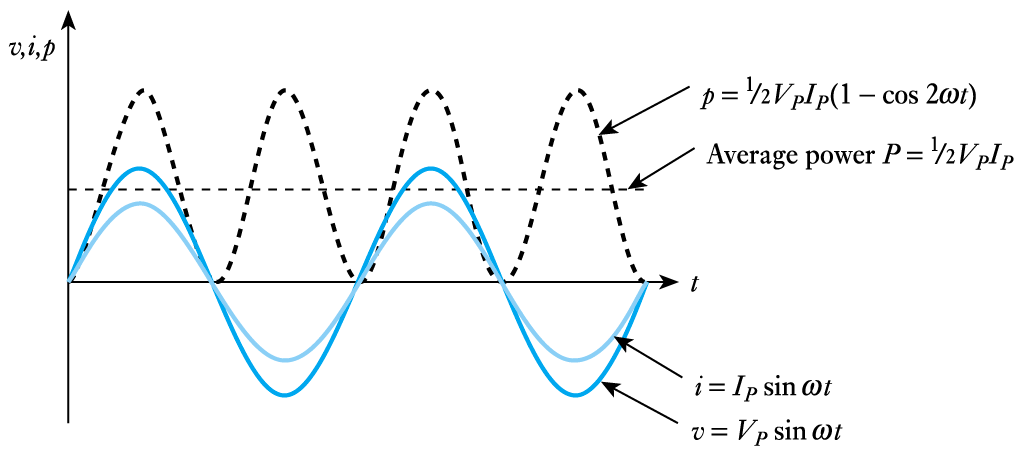
- Suppose a voltage $v=V_P \text{ sin } \omega t$ is applied across a resistance $R$. The resultant current $i$ will be
$$ i = \frac{v}{R} = \frac{V_P \text{ sin }\omega t}{R} = I_P \text{ sin } \omega t $$- The result power $p$ will be
\begin{align*} p &= vi \\ &= V_P \text{ sin }\omega t \times I _P \text{ sin } \omega t \\ &= V_P I_P ( \text{sin}^2 \; \omega t) \\ &= V_P I_P (\frac{1 - \text{cos } 2 \omega t}{2}) \end{align*}- The average value of $(1 - \text{cos } 2ωt) \text{ is } 1$,so
Average Power \begin{align*} &= \frac{1}{2} V_PI_P \\ &= \frac{V_P}{ \sqrt{2}} \times \frac{I_P}{ \sqrt{2}} \\ &= VI \\ \end{align*}where $V$ and $I$ are the r.m.s. voltage and current
- 📷 Relationship between $v$, $i$ and $p$ in a resistor (can be seen here)
- From our discussion of capacitors we know that the current leads the voltage by $90 ^\circ$. Therefore, if a voltage $v = V_P \text{ sin } ωt$ is applied across a capacitance $C$, the current will be given by $i$ = $I _p \text{ cos } ωt$
-
(Continued)
- The first part represents the power dissipated in resistive components. Average power dissipation is

\begin{align*} p &= \frac{1}{2} V_P I_P \; (\text{cos } \phi) = \frac{V _P}{\sqrt{2}} \times \frac{I _P}{\sqrt{2}} \times (\text{cos}\phi) = VI \text{cos} \phi \end{align*}
- The average power dissipation given by
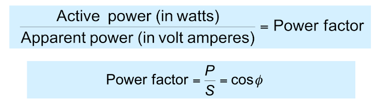
$$ p = \frac{1}{2} V_P I_P \; (\text{cos}\phi) = VI \text{cos} \phi $$ is termed the active power in the circuit and is measured in watts ($W$)
- The product of the r.m.s. voltage and current VI is termed the apparent power, $S$. To avoid confusion this is given the units of volt amperes ($VA$)
- From the above discussion it is clear that
\begin{align*} p &= VI \; \text{cos} \phi \\ &= S \text{ cos} \phi \end{align*}- In other words, the active power is the apparent power times the cosine of the phase angle.
- This cosine is referred to as the power factor
Power in Inductors
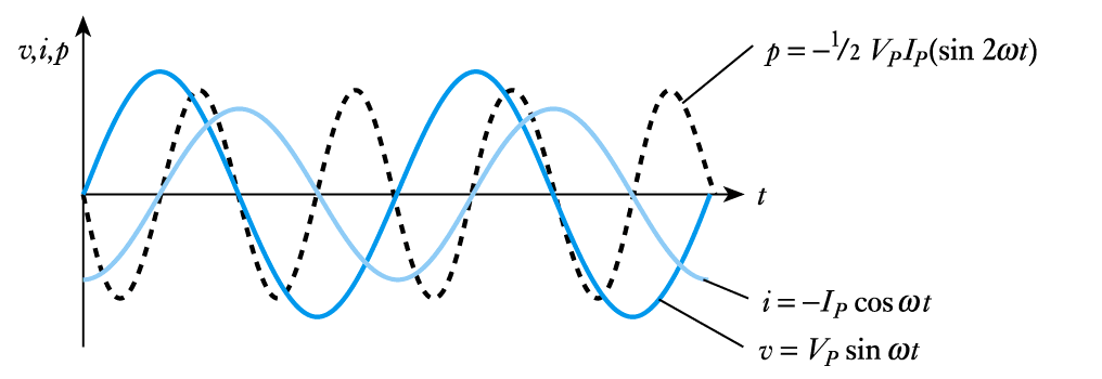
- From our discussion of inductors we know that the current lags the voltage by $90 ^\circ$. Therefore, if a voltage $v=V_P \text{ sin } ωt$ is applied across an inductance $L$, the current will be given by $i = -I_P \text{ cos } ωt$
Therefore \begin{align*} p &= vi \\ &= V_P \text{ sin } \omega t \times I_P \text{ cos } \omega t\\ &= V_P I_P (\text{sin } \omega t \times \text{cos } \omega t) \\ &= V_P I_P (\frac{\text{sin }2 \omega t}{2}) \\ \end{align*}- Again the average power is zero
- 📷 Relationship between $v$, $i$ and $p$ in an inductor
Circuit with Resistance and Reactance
- When a sinusoidal voltage $v = V_P \text{ sin } ωt $ is applied across a circuit with resistance and reactance, the current will be of the general form $i = I_P \text{ sin } (ωt - \phi )$
- Therefore, the instantaneous power, $p$ is given by
\begin{align*} p &= vi \\ &= V_P \text{ sin } \omega t \times I_P \text{ sin } (\omega t - \phi)\\ &= \frac{1}{2} V_P I_P \; \text{cos } \phi - \text{ cos }(2 \omega t - \phi)\\ p &= \frac{1}{2} V_P I_P \; \text{cos } \phi - \frac{1}{2} V_P I_P \; \text{cos } (2 \omega t -\phi) \\ p &= \frac{1}{2} V_P I_P \; \text{cos } \phi - \frac{1}{2} V_P I_P \; \text{cos } (2 \omega t -\phi) \end{align*}- The expression for $p$ has two components
- The second part oscillates at $2 \omega$ and has an average value of zero over a complete cycle
– this is the power that is stored in the reactive elements and then returned to the circuit within each cycle
-
Power Factor Correction
- Power factor is particularly important in high-power applications
- Inductive loads have a lagging power factor
- Capacitive loads have a leading power factor power factor
- Many high-power devices are inductive
– a typical AC motor has a power factor of $0.9$ lagging
– the total load on the national grid is $0.8-0.9$ lagging
– this leads to major efficiencies
– power companies therefore penalise industrial users who introduce a poor power factor
- The problem of poor power factor is tackled by adding additional components to bring the power factor back closer to unity
– a capacitor of an appropriate size in parallel with a lagging load can ‘cancel out’ the inductive element
– this is power factor correction
– a capacitor can also be used in series but this is less common (since this alters the load voltage)
– for examples of power factor correction see Examples 7.2 and 7.3 in the course textActive and Reactive Power
- When a circuit has resistive and reactive parts, the resultant power has 2 parts:
– The first is dissipated in the resistive element. This is the active power, $P$
–The second is stored and returned by the reactive element. This is the reactive power, $Q$ , which has units of volt amperes reactive or var
- While reactive power is not dissipated it does have an effect on the system
– for example, it increases the current that must be supplied and increases losses with cables
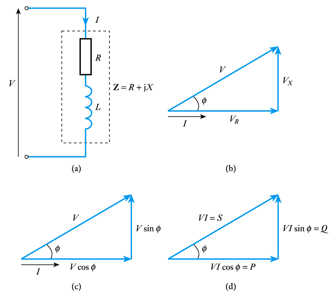
- 📷 Consider an $RL$ circuit
– the relationship between the various forms of power can be illustrated using a power triangle
- Therefore
- \begin{align*} \text{Active Power } \; P =& VI \text{ cos } \phi \; \; \; \text{ watts} \\ \\ \text{Reactive Power } \; Q =& VI \text{ sin } \phi \; \; \; \text{ var} \\ \\ \text{Apparent Power } \; S =& VI \; \; \qquad \text{ VA} \\ \\ S^2 =& p^2 + Q^2 \end{align*}
-
Power Measurement
- When using AC, power is determined not only by the r.m.s. values of the voltage and current, but also by the phase angle (which determines the power factor)
– consequently, you cannot determine the power from independent measurements of current and voltage
- In single-phase systems power is normally measured using an electrodynamic wattmeter
– measures power directly using a single meter which effectively multiplies instantaneous current and voltage
- In three-phase systems we need to sum the power taken from the various phases
– in three-wire arrangements we can deduce the total power from measurements using $2$ wattmeter– in a four-wire system it may be necessary to use $3$ wattmeter– in balanced systems (systems that take equal power from each phase) a single wattmeter can be used, its reading being multiplied by $3$ to get the total powerThree-Phase Systems
- So far, our discussion of AC systems has been restricted to single-phase arrangement
– as in conventional domestic supplies
- In high-power industrial applications we often use three-phase arrangements
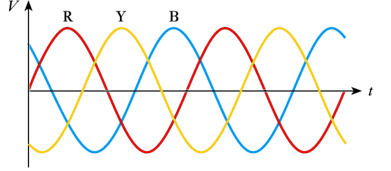
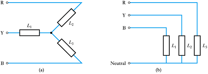
– these have three supplies, differing in phase by $120^\circ$
– phases are labeled red, yellow and blue($R$, $Y$ & $B$)
- Relationship between the phases in a three-phase arrangement
- 📷 Three-phase arrangements may use either 3 or 4 conductors - it can be seen at this link
- When using AC, power is determined not only by the r.m.s. values of the voltage and current, but also by the phase angle (which determines the power factor)
-
Further Study
- 🎥 Watch a video on power factor correction for an electric motor - Adobe Flash video
- The Further Study section at the end of Chapter 7 is concerned with power factor correction for a high-power motor.
- Your task is to calculate the size of capacitor needed to achieve a specific power factor.
- Do the sums and then watch the video at the above link.
Key Points
- In resistive circuits the average power is equal to $VI$, where $V$ and $I$ are r.m.s. values
- In a capacitor the current leads the voltage by $90^\circ$ and the average power is zero
- In an inductor the current lags the voltage by $90^\circ$ and the average power is zero
- In circuits with both resistive and reactive elements, the average power is $VI$ cos $\phi$
- The term cos $\phi$ is called the power factor
- Power factor correction is important in high-power systems
- High-power systems often use three-phase arrangements
-
- 7.15 A sinusoidal signal of $20 V$ peak at $50 Hz$ is applied to a load consisting of a $10 \Omega$ resistor and a 16 mH inductor connected in series. Calculate the power factor of this arrangement and the active power dissipated in the load.
- 7.16 Determine the value of capacitor needed to be added in series with the circuit of Exercise 7.11 to produce a power factor of $1.0$. Calculate the active power that would be dissipated in the circuit with the addition of such a capacitor.
- 7.17 Explain the difference between three- and four- conductor arrangements of three-phase power supplies.
- 7.18 Explain why it is not possible to calculate the power dissipated in an AC network by multiplying the readings of a voltmeter and an ammeter.
- 7.19 Explain how it is possible to measure power directly in a single-phase system.
- ⬇ Tutorial Solutions
- ⬇Download chapter 7 tutorial
Exercises
- 7.1 If a sinusoidal voltage with a frequency of $50 Hz$ is applied across a resistor, at what frequency does the instantaneous power supplied to the resistor vary?
- 7.2 A sinusoidal voltage $v = 10 \text{ sin } 377t$ is applied to a resistor of $50 \Omega$. Calculate the average power dissipated in it.
- 7.3 If a sinusoidal voltage with a frequency of $50 Hz$is applied across a capacitor, at what frequency does the instantaneous power supplied to the capacitor vary?
- 7.4 A sinusoidal voltage $v = 10 \text{ sin } 377t$ is applied across a capacitor of $1 \mu F$. Calculate the average power dissipated in it.
- 7.5 If a sinusoidal voltage with a frequency of $50 Hz$ is applied across an inductor, at what frequency does the instantaneous power supplied to the inductor vary?
- 7.6 A sinusoidal voltage $v = 10 \text{ sin } 377t$ is applied across an inductor of $1 mH$. Calculate the average power dissipated in it.
- 7.7 Explain the meanings of the terms active power, apparent power and power factor.
- 7.8 The voltage across a component is $100 V$ r.m.s. and the current is $7 A$ r.m.s. If the current lags the voltage by 60°, calculate the apparent power, the power factor and the active power.
- 7.9 Explain the difference between the units of watts, $VA$ and var.
- 7.10 A sinusoidal voltage of $100 V$ r.m.s. at $50 Hz$ is applied across a series combination of a $40 \Omega$ resistor and an inductor of $100 mH$. Determine the r.m.s. current, the apparent power, the power factor, the active power and the reactive power.
- 7.11 A machine operates on a $250 V$ supply at $60 Hz$; it is rated at 500 VA and has a power factor of $0.8$. Determine the apparent power, the active power, the reactive power and the current in the machine.
- 7.12 Explain what is meant by power factor correction and explain why this is of importance in high-power systems.
- 7.13 Calculate the value of capacitor required to be added in parallel with the machine of Exercise 7.11 to achieve a power factor of $1.0$.
- 7.14 Calculate the value of capacitor required to be added in parallel with the machine of Exercise 7.11 to achieve a power factor of $0.9$.