Wk 11
Transient Behaviour
- Introduction
- Charging Capacitors and Energising Inductors
- Discharging Capacitors and De-energising Inductors
- Response of First-Order Systems
- Second-Order Systems
- Higher-Order Systems
Introduction
- So far we have looked at the behaviour of systems in response to:
– fixed DC signals
– constant AC signals- We now turn our attention to the operation of circuits before they reach steady-state conditions
– this is referred to as the transient response- We will begin by looking at simple $RC$ and $RL$ circuits
-
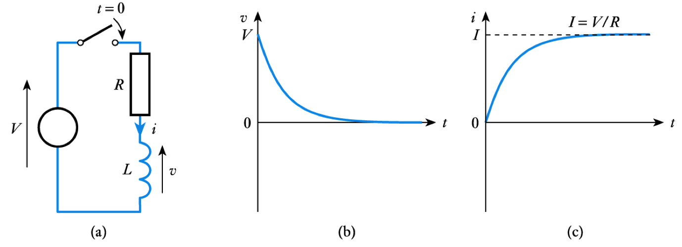
Inductor energising
- A similar analysis of this circuit
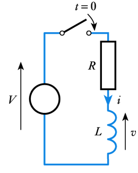
gives
\begin{align*} v =& Ve ^{\Large \frac{Rt}{L}} = Ve ^{\Large \frac{t}{\text{T}}} \\ \\ i =& I( 1 - e ^{\Large \frac{Rt}{L}}) = I (1 - e ^{\Large \frac{t}{\text{T}}}) \end{align*}
where $I = V/R$
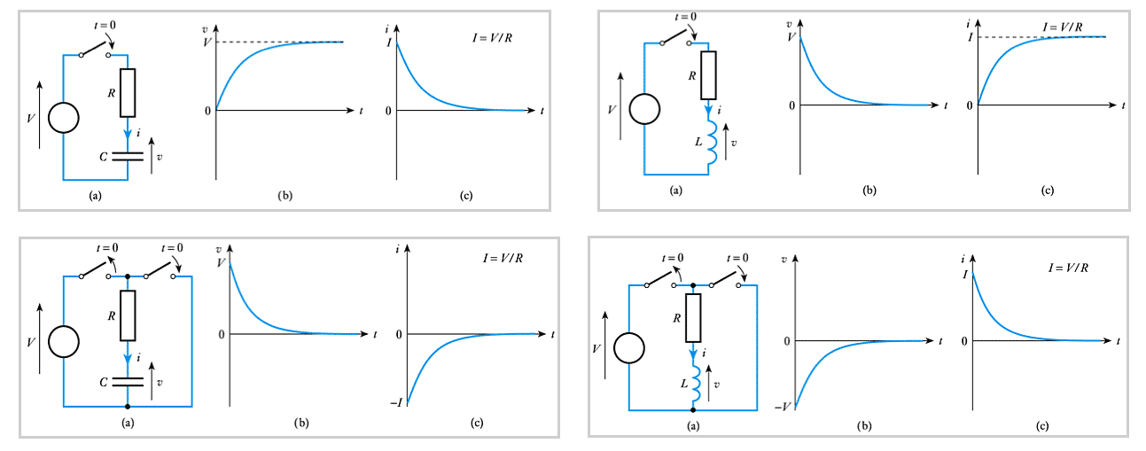
– see Section 9.2.2 for this analysis- 📷 Thus, again, both the voltage and current have an exponential form - see here
Charging Capacitors and Energising Inductors
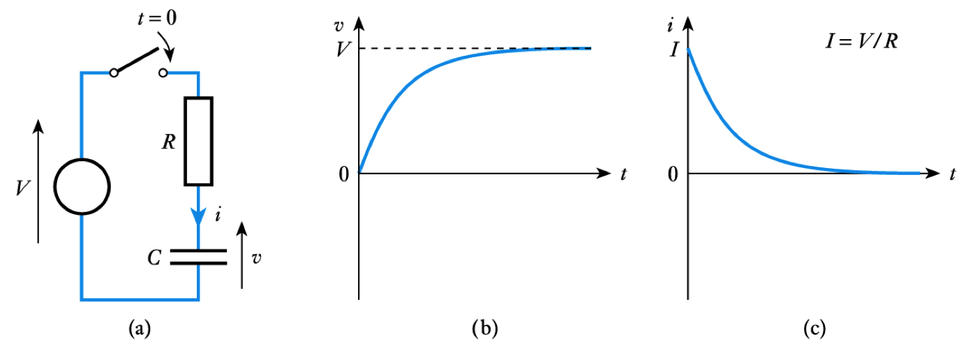
- Capacitor Charging - Consider the circuit shown here
– Applying Kirchhoff’s voltage law
$ iR + v = V $– Now, in a capacitor
$ i= C\frac{dv}{dt} $– which substituting gives
$ CR\frac{dv}{dt} + v = V $- The above is a first-order differential equation with constant coefficients
- Assuming $V_C = 0 $ at $t = 0$, this can be solved to give
$$ \large {v = V(1-e ^{\frac{t}{CR}}) = V(1-e ^{\frac{t}{\text{T}}})} $$
– see Section 9.2.1 of the course text for this analysis
- Since $i = C \text{d} \; v / \text{d}t$ this gives (assuming $V _C = 0$ at $t = 0$)
$$ \large {i = Ie ^{\frac{t}{CR}} = Ie ^{\frac{t}{\text{T}}}} $$
– where $I = V/R$- 📷 Thus both the voltage and current have an exponential form - see here
- A similar analysis of this circuit
-
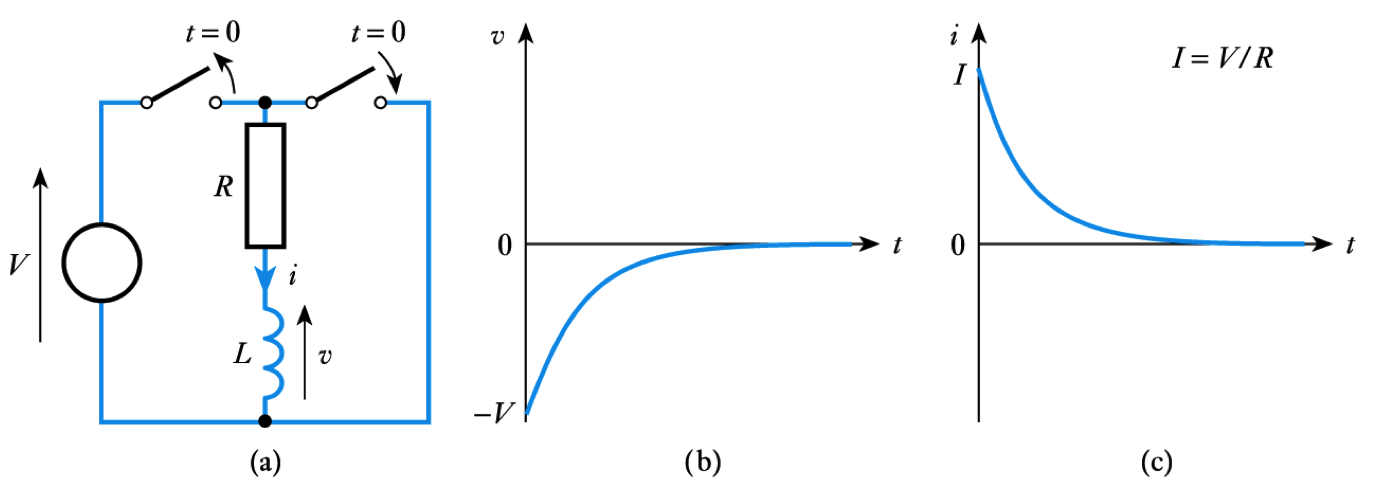
Inductor de-energising
- A similar analysis of this circuit
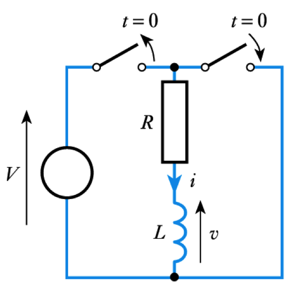
gives
\begin{align*} v =& - Ve ^{\Large \frac{Rt}{L}} = - Ve ^{\Large \frac{t}{\text{T}}} \\ \\ i =& Ie ^{\Large \frac{Rt}{L}} = I e ^{\Large \frac{t}{\text{T}}} \end{align*}– where $I = V/R$– see Section 9.3.1 for this analysis
- 📷 And once again, both the voltage and the current take the form of decaying exponentials
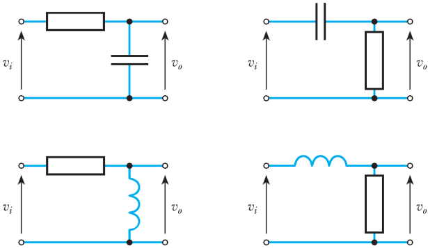
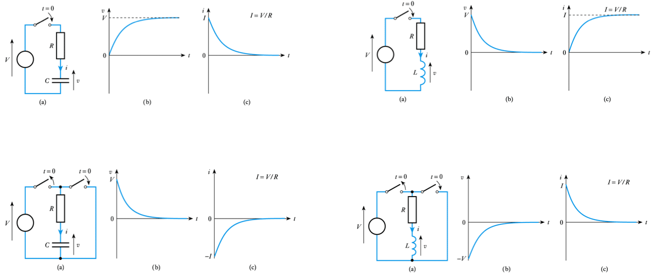
- 📷 A comparison of the four circuits
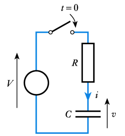
Discharging Capacitors and De-energising Inductors
- Capacitor discharging - Consider this circuit for discharging a capacitor
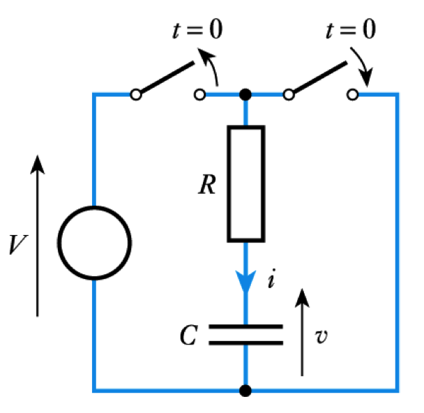
– At $t = 0$, $V_C = V$
– From Kirchhoff’s voltage law
$$\large{iR + v = 0}$$– giving
$$\large{CR \frac{dv}{dt} + v = 0}$$
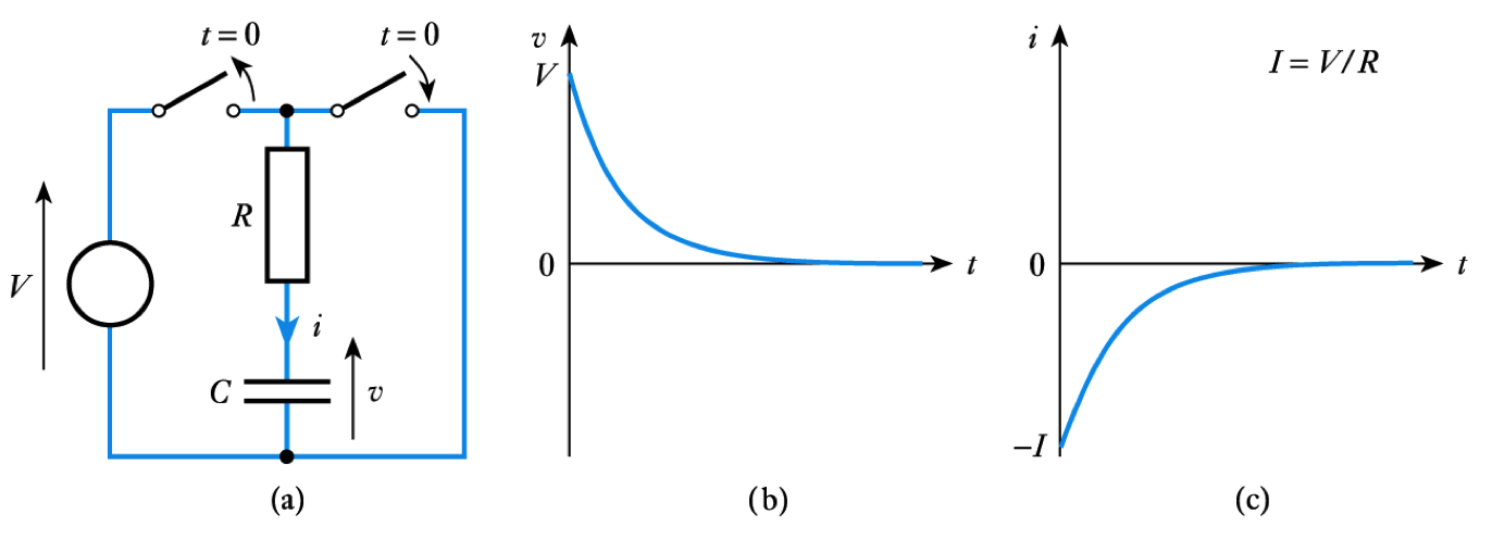
- Solving this as before gives
\begin{align*} v =& Ve ^{\Large \frac{t}{CR}} = Ve ^{\Large \frac{t}{\text{T}}} \\ \\ i =& - Ie ^{\Large \frac{t}{CR}} = - I e ^{\Large \frac{t}{\text{T}}} \end{align*}– where $I = V/R$– see Section 9.3.1 for this analysis
- 📷 In the above case, both the voltage and the current take the form of decaying exponentials - see here
- A similar analysis of this circuit
-
(Continued)
- The nature of exponential curves
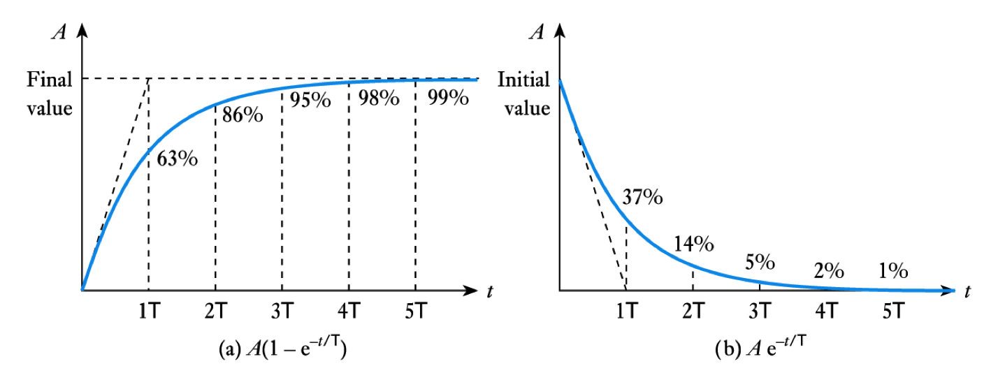
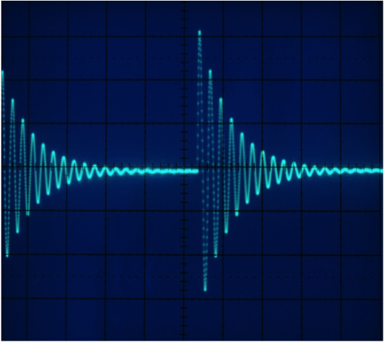
- 📷 Response of first-order systems to a square waveform
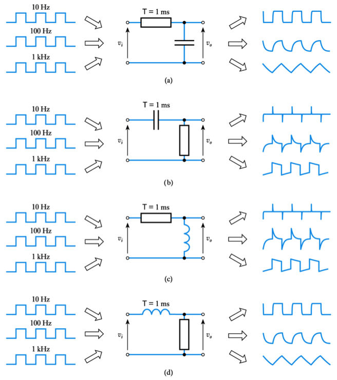
– see Section 9.4.3- 📷 Response of first-order systems to a square waveform of different frequencies
– see Section 9.4.3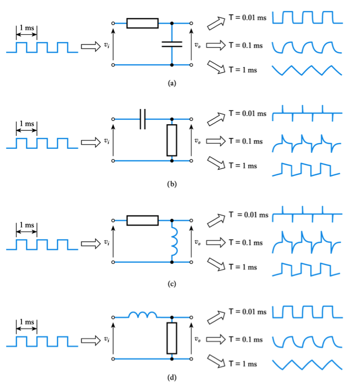
Response of First-Order Systems
- Initial and final value formulae
– increasing or decreasing exponential waveforms (for either voltage or current) are given by:
\begin{align*} v =& V_f +(V_i - V_f)e ^{\large - t / \text{T}} \\ \\ i =& I_f +(I_i - I_f)e ^{\large - t / \text{T}} \end{align*}
– where $V_i$ and $I_i$ are the initial values of the voltage and current
– where $V_f$ and $I_f$ are the final values of the voltage and current– the first term in each case is the steady-state response
– the second term represents the transient response
– the combination gives the total response of the arrangement
- Example – see Example 9.3 from course text
The input voltage to the following $CR$ network undergoes a step change from $5$ V to $10$ V at time $t = 0$. Derive an expression for the resulting output voltage
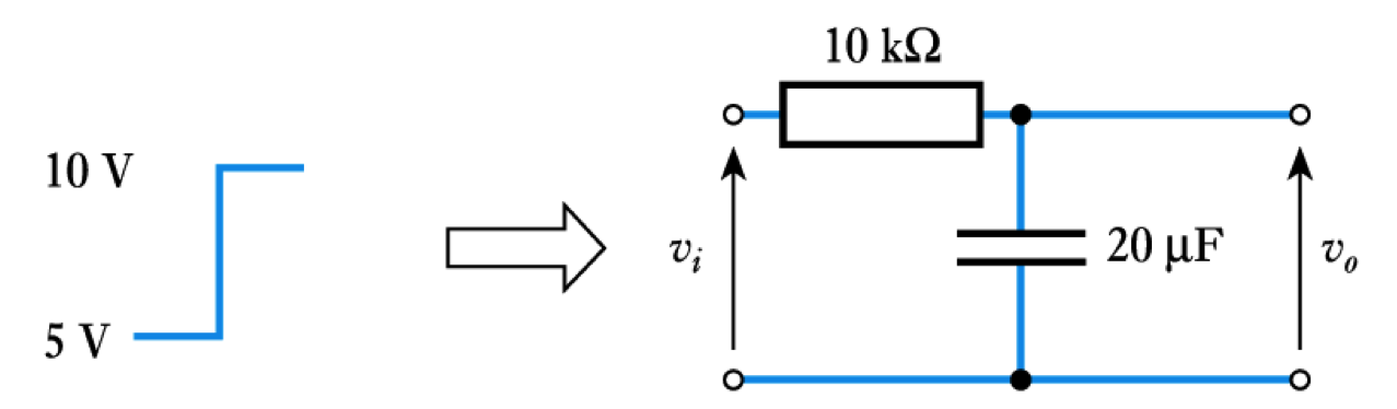
Here the initial value is $5$ V and the final value is $10$ V. The time constant of the circuit equals $CR = 10 \times 10^3 \times 20 \times 10^-6 = 0.2s.$
Therefore, from above, for $t \geq 0 $
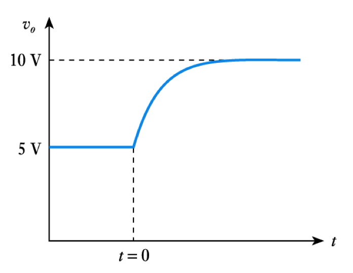
\begin{align*} v =& V_f + (V_i - V_f)e ^{\Large -t/\text{T}} \\ \\ =& 10 + (5 - 10)e ^{\Large -t/ 0.2} \\ \\ =& 10 - 5e ^{\Large -t/ 0.2} \text{ volts} \end{align*} - The nature of exponential curves
-
(Continued)
- Response of second-order systems
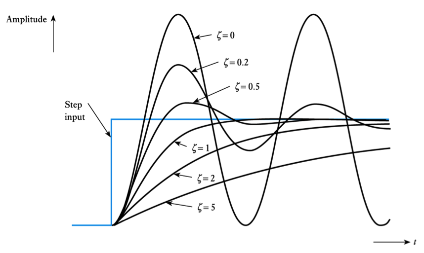
$\zeta = 0$ undamped$\zeta$ < $1$ under damped$\zeta = 1 $ critically damped$\zeta$ > $1$ over damped
Higher-Order Systems
- Higher-order systems are those that are described by third-order or higher-order equations
- These often have a transient response similar to that of the second-order systems described earlier
- Because of the complexity of the mathematics involved, they will not be discussed further here
Second-Order Systems
- Circuits containing both capacitance and inductance are normally described by second-order differential equations. These are termed second-order systems
– for example, this circuit is described by the equation below it
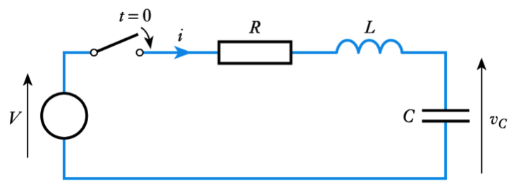
$$ LC \frac{d^2v_C}{dt^2} + RC \frac{dv_C}{dt} +v_C = V $$- When a step input is applied to a second-order system, the form of the resultant transient depends on the relative magnitudes of the coefficients of its differential equation. The general form of the response is
$$ \frac{1}{\omega_n \; ^2} \frac{d^2 y}{dt^2} + \frac{2 \zeta}{\omega_n} \frac{d y}{dt} + y = x $$– where $\omega_n $ is the undamped natural frequency in rad/s and $\zeta$ (Greek Zeta) is the damping factor

- Response of second-order systems
-
Further Study
- 🎥 Watch a video on determination of a circuit's time constant - Adobe Flash video
- The Further Study section at the end of Chapter 9 considers the problem of determining the time constant of a circuit, so that the initial and final value theorems can be applied.
- Two sample circuits are given so that you can test your understanding.
- Calculate the time constants of the circuits and then check your results by looking at the video.
Key Points
- The charging or discharging of a capacitor, and the energising and de-energising of an inductor, are each associated with exponential voltage and current waveforms
- Circuits that contain resistance, and either capacitance or inductance, are termed first-order systems
- The increasing or decreasing exponential waveforms of first-order systems can be described by the initial and final value formulae
- Circuits that contain both capacitance and inductance are usually second-order systems. These are characterised by their undamped natural frequency and their damping factor
-
- 9.9 The switch in the following circuit is closed at $t = 0$. Derive an expression for the current in the circuit and hence calculate the current in the inductor at $t = 20$ ms.
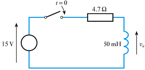
- 9.10 In the circuit of Exercise 9.9, what is the final or steady‐state voltage across the inductor?
- 9.11 In the circuit of Exercise 9.9, what is the final or steady‐state voltage across the resistor?
- 9.12 A capacitor of $25 \;\mu F$ is initially charged to a voltage of $50$ V. At time $t = 0$, a resistance of $1 \; k \Omega$ is connected directly across its terminals. Derive an expression for the voltage across the capacitor as it is discharged and hence determine the time taken for its voltage to drop to $10$ V.
- 9.13 An inductor of $25$ mH is passing a current of $1$ A. At $t = 0$, the circuit supplying the current is instantly replaced by a resistor of $100 \Omega$ connected directly across the inductor. Derive an expression for the current in the inductor as a function of time and hence determine the time taken for the current to drop to $100$ mA.
- 9.14 What is meant by a ‘first-order system’, and what kind of circuits fall within this category?
- 9.15 Explain how the equation for an increasing or decreasing exponential waveform may be found using the initial and final values of the waveform.
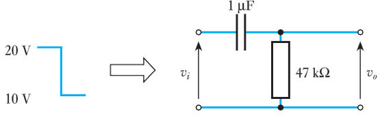
- 9.16 The input voltage to the following $RC$ network undergoes a step change from $20$ V to $10$ V at time $t = 0$. Derive an expression for the resulting output voltage.
- ⬇Download chapter 9 tutorial
Exercises
- 9.1 Explain the meanings of the terms ‘steady-state response’ and ‘transient response’.
- 9.2 When a voltage is suddenly applied across a series combination of a resistor and an uncharged capacitor, what is the initial current in the circuit? What is the final, or steady-state, current in the circuit?
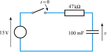
- 9.3 The switch in the following circuit is closed at $t = 0 s$. Derive an expression for the current in the circuit after this time and hence calculate the current in the circuit at $t = 4s$.
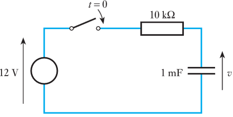
- 9.4 The switch in the following circuit is closed at $t = 0 s$. Derive an expression for the voltage v and hence calculate the voltage across the capacitor at $t = 5 s$
- 9.5 In the circuit of Exercise 9.4 what is the final or steady‐state voltage across the capacitor?
- 9.6 In the circuit of Exercise 9.4 what is the final or steady‐state voltage across the resistor?
- 9.7 When a voltage is suddenly applied across a series combination of a resistor and an inductor, what is the initial current in the circuit? What is the final, or steady-state, current in the circuit?
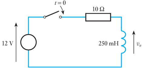
- 9.8 The switch in the following circuit is closed at $t = 0$. Deduce an expression for the output voltage of the circuit and hence calculate the time at which the output voltage will be equal to $8$ V.
-
- 9.22 Under what circumstances does the behaviour of a first-order high-pass filter resemble that of a differentiator?
- 9.23 Under what circumstances does the behaviour of a first-order low-pass filter resemble that of an integrator?
- 9.24 What is meant by a ‘second-order system’, and what kind of circuits fall within this category?
- 9.25 Derive an expression for the current in the circuit of Figure 9.8.
- 9.26 Explain what is meant by the terms ‘undamped natural frequency’ and ‘damping factor’ as they apply to second-order systems.
- 9.27 What is meant by ‘critical damping’ and what value of the damping factor corresponds to this situation?
- ⬇ Tutorial Solutions
Exercises (cont.)
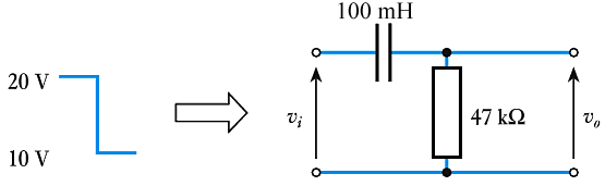
- 9.17 The input voltage to the following $RL$ network undergoes a step change from $20$ V to $10$ V at time $t = 0$. Derive an expression for the resulting output voltage.
- 9.18 What is meant by a saturating exponential waveform?
- 9.19 What is meant by a decaying exponential waveform?
- 9.20 Sketch the exponential waveform $v = 5e ^{\large − t /10}$.
- 9.21 For each of the following circuit arrangements, sketch the form of the output voltage when the period of the square-wave input voltage is:
(a) much greater than the time constant of the circuit;
(b) equal to the time constant of the circuit;
(c) much less than the time constant of the circuit.